Table of Contents
Advertisement
Quick Links
Advertisement
Table of Contents

Related Manuals for Honeywell IF2


Summary of Contents for Honeywell IF2
- Page 1 Network Reader User Guide...
- Page 2 Disclaimer Honeywell International Inc. (“HII”) reserves the right to make changes in specifications and other information contained in this document without prior notice, and the reader should in all cases consult HII to determine whether any such changes have been made. The information in this publication does not represent a commitment on the part of HII.
-
Page 3: Table Of Contents
How to Ground the IF2 ......................9 How to Provide Adequate Heat Sinking............... 10 Install the IF2.......................... 10 Connect the IF2 to Your Network ................... 11 Set the Date and Time ....................... 12 How to Use the IF2 Securely ....................12... - Page 4 Configure Ethernet Settings.....................14 Configure Common Network Settings................15 Configure Security ........................16 Control Access Services......................17 Set Up Logins..........................18 Configure the IF2 to Use a Password Server ............18 Change the Default Login...................20 Disable Access Through the Serial Port ...............21 Manage Certificates ........................21 View Certificates ........................21 Install and Uninstall Certificates ..................22...
- Page 5 Antenna Sequence: First through Eighth..............31 Configure the BRI Server ....................31 View the BRI Server Log ......................32 Configure LLRP Settings ......................33 Chapter 4 - Install Applications on the IF2 with Expanded Memory Option.........................35 Create a Configuration File ......................35 Auto-Start Applications at Boot Time ..................36 About .NET Support ........................36...
- Page 6 Chapter 5 - Manage, Troubleshoot, and Upgrade the IF2 ..... 43 Manage the IF2 ..........................43 Use the Device Configuration Web Service...............43 Open a Serial or USB Connection to the IF2..............44 Open a Serial Connection to the IF2 ................45 Open a USB Connection to the IF2 ................45 Maintain the IF2...........................47...
- Page 7 Switch the Low Side with IF2 Power................58 Switching the High Side With External Power ............59 Drive a DC Relay to Control an AC Load...............59 Use the Power Interface ......................60 Appendix A - Specifications ................61 IF2 Specifications ........................61 RFID Specifications........................62 Port Pin Assignments .........................62 GPIO Port ..........................62...
- Page 8 IF2 Network Reader User Guide...
-
Page 9: Customer Support
Honeywell International Inc. provides service for all of its products through service centers throughout the world. To obtain warranty or non-warranty service, return your product to Honeywell (postage paid) with a copy of the dated purchase record. To learn more, go to www.honeywellaidc.com... - Page 10 IF2 Network Reader User Guide...
-
Page 11: Chapter 1 - About The Rfid Reader
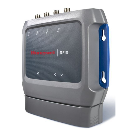
The IF2 Network Reader is an RFID reader that provides connectivity between tag data and an enterprise system. IF2 Network Reader Note: The IF2 does not ship with RFID antennas. For more information on these accessories, contact your sales representative. IF2 Network Reader User Guide... -
Page 12: About The Leds
IF2 in a Wired Ethernet Network About the LEDs The IF2 has six LEDs that indicate the status of the reader during operation. Use the next table to identify the LED icons on the front panel of the IF2. IF2 LED Descriptions... -
Page 13: About The Ready-To-Work Indicator
About the Ready-to-Work Indicator The blue Ready-to-Work indicator shows when an application is communicating with the Basic Reader Interface (BRI) server or LLRP client on the IF2. The next table explains the different states of the Ready-to-Work indicator. Ready-to-Work Indicator Status Descriptions... -
Page 14: About The Top Panel Ports
The Ethernet port also supports POE. To use POE you need an 802.3at compliant power converter. For more information, contact your sales representative. About the Top Panel Ports The IF2 top panel ports consist of four antenna ports, a reset switch, and a USB service port. USB service port... -
Page 15: How To Communicate With The If2
By default, the IF2 is configured to be a DHCP client and accepts offers from any DHCP server. Therefore, the IF2 will work out of the box if you connect it to your network and use a DHCP server to assign it an IP address. In this case, you config- ure the IF2 using the web browser interface from a desktop PC. - Page 16 4. To set the IP address, press 1 and enter the static IP address in the entry field. 5. Press Enter. The static IP address is set. If you do not need to set the subnet mask or IP router values, you can now continue to configure the IF2 through the web browser interface. For help, see "Use the Web Browser Interface"...
-
Page 17: Use The Web Browser Interface
15 minutes. Note: If you access the Internet using a proxy server, add the IF2 IP address to your Exceptions list. The Exceptions list contains the addresses that you do not want to use with a proxy server. -
Page 18: Save Configuration Changes
Network" on page For help with configuring RFID reader settings, see "Configure BRI Settings" on page For more information on other methods for managing the IF2, see "Manage the IF2" on page Save Configuration Changes After you make configuration changes, click Activate Changes in the browser win- dow to save your changes and immediately make the changes active. -
Page 19: Disable Help In The Web Browser Interface
The Help text is disabled. How to Install the IF2 This section explains how to properly install the IF2 reader and how to mount it to a wall using the IF2 Network Reader Drilling Template Instructions that ship in the box with the IF2. -
Page 20: How To Provide Adequate Heat Sinking
IF2 will not overheat in most cases if the ambient temperature is cooler than 40 º (104 Adding a heat sink to the rear plate of the IF2 may provide adequate cooling to allow continuous reading operation in high temperature environments, such as what you might encounter inside of an unventilated enclosure. Periodic external triggering of the IF2 to read tags will help keep the internal temperatures low enough to operate without an additional heat sink. -
Page 21: Connect The If2 To Your Network
5. Ground the IF2. Connect the IF2 to Your Network After you place the IF2 in its mounting location, you can connect it to your network. 1. Install the IF2 in its mounting location. For help, see "How to Install the IF2" on page 2. -
Page 22: Set The Date And Time
Set the Date and Time After you have installed the IF2, you can set the date and time via the web browser interface. 1. Connect to the IF2 via the web browser interface. For help, see "Use the Web Browser Interface" on page 2. -
Page 23: Chapter 2 - Configure Network Settings
CHAPTER CONFIGURE NETWORK SETTINGS This chapter describes how to configure network settings for the IF2 and includes these topics: • Configure the Settings for Your Network • Configure Security • Manage Certificates This chapter assumes that you are familiar with your network, networking terms, and the type of security implemented by your network. -
Page 24: Configure Ethernet Settings
If you need to configure other network settings such as DNS addresses and suffixes or a SYSLOG destination, see "Configure Common Network Settings" on page 3. Click Activate Changes to save your changes and immediately make them active. IF2 Network Reader User Guide... -
Page 25: Configure Common Network Settings
Parameter Description Enable DHCP Check this check box if you want the IF2 to get its IP address from a DHCP server. If this check box is not checked, you need to specify the IP address, subnet mask, and IP router for your network. -
Page 26: Configure Security
Domain name or IP address of the SYSLOG server. Configure Security Note: Before you configure security settings for this IF2, you should be familiar with the type of security implemented for your network. The IF2 supports a variety of security features to help maintain the integrity of your secure network. -
Page 27: Control Access Services
"How to Use the IF2 Securely" on page Control Access Services Access services are the different ways that users can access and configure the IF2. You can control how developers access the IF2 by enabling or disabling these ser- vices: •... -
Page 28: Set Up Logins
Configure the IF2 to Use a Password Server If you use a password server to manage users who log in to this IF2, you need to tell the IF2 how to communicate with the password server and then you need to con- figure the password server. - Page 29 Port number of the secondary RADIUS server. Default is 1812. Enable Serial Configuration Enable basic network configuration using the serial or USB port. Note: USB is not supported on the IF2 with Expanded Memory Option. IF2 Network Reader User Guide...
-
Page 30: Change The Default Login
Password Parameter Descriptions Parameter Description Username Enter the user name you need to use to log in to this IF2. The user name can be from 1 to 32 characters long. You must always specify a user name. Default is intermec. Password Enter the password you need to use to log in to this IF2. -
Page 31: Disable Access Through The Serial Port
LLRP client connections, and secure web services. You can use a third-party certif- icate authority to issue unique client certificates and a root certificate. Note: To install or uninstall certificates, you need to access the IF2 via a secure web browser. For help, see "Use the Web Browser Interface"... -
Page 32: Install And Uninstall Certificates
Note: If you are not using a secure web browser, you will be prompted to log in again. Click A secure session is available and log in to the IF2. If a Security Alert dialog box appears, click Yes to proceed. Repeat Steps 1 and 2. - Page 33 4. (Server Certificate only) In the Enter the associated passphrase for this certificate field, carefully enter the passphrase for the certificate. 5. Click Import Certificate. If a Security Alert dialog box appears, click Yes to proceed. IF2 Network Reader User Guide...
- Page 34 IF2 Network Reader User Guide...
-
Page 35: Chapter 3 - Develop And Use Rfid Applications
For the IF2 with Expanded Memory Option, the applications you develop can be hosted and run locally on the reader. Note: This chapter applies to both the standard and expanded memory options of the IF2. IF2 Network Reader User Guide... -
Page 36: Rfid Applications And The If2
Software>Software and Tools>Developer Library>SDKs for Windows>Intermec Resource Kits>Developer Tools. Create RFID Applications An RFID application can communicate directly with the IF2 BRI Server using the BRI protocol, or it can communicate with the IF2 using the Low-Level-Reader Pro- tocol (LLRP). -
Page 37: Configure Bri Settings
"Configure the BRI Server" on page Change BRI Attribute Settings BRI attribute settings control how the IF2 reader module reads tags. Follow the next procedure to change attribute settings. Note: The BRI attribute settings in the web interface define the default BRI attributes when a client initially connects to the BRI. -
Page 38: Tag Types
This setting is equivalent to the FIELDSEP BRI attribute. ID Report Enables or disables tag ID reporting after a Read, Write, or Lock command is exe- cuted: • For ISO tags, the tag identifier corresponds to TAGID. IF2 Network Reader User Guide... -
Page 39: No Tag Report
Enables a timeout mode. Instead of specifying the number of antenna or ID tries, you specify an antenna or ID timeout value. If the IF2 does not find any tags after an antenna or ID try, the reader waits this long before starting the next antenna or ID try. -
Page 40: Session
This setting is equivalent to the ANTTRIES BRI attribute. EPCC1G2 Advance Medium Access Mode Selects low-level protocol (such as tari and back-link frequency) settings. If you are using CAEN tags, you must enable this mode before the tags can be read. IF2 Network Reader User Guide... -
Page 41: Dense Reader Mode
The IF2 BRI server handles communication between your application and the RFID module. When your application is communicating with the BRI server, the blue Intermec Ready-To-Work Indicator on the IF2 front panel turns on and stays on. For more information, see "About the Ready-to-Work Indicator"... -
Page 42: View The Bri Server Log
BRI applications will not be able to connect to the IF2. BRI TCP Port Specifies the TCP port used for incoming connections to the BRI server. This port must be unique for all TCP services running on the IF2. Valid range is 2189 to 65535. Default is 2189. Enable Logging Enables/disables logging of BRI server events. -
Page 43: Configure Llrp Settings
Follow the prompts to save the log file to your desktop PC. Configure LLRP Settings The IF2 supports version 1.0.1 of the EPCglobal Low-Level Reader Protocol (LLRP), which establishes a specific interface method between a reader and its corresponding client. Follow the next procedure to configure LLRP settings. - Page 44 To disconnect an existing LLRP connection, click Terminate. • To connect to a remote LLRP client, enter information in the Reader-Initiated Connections section, and then click Initiate. 3. Click Activate Changes to save your changes and immediately make them active. IF2 Network Reader User Guide...
-
Page 45: Chapter 4 - Install Applications On The If2 With Expanded Memory Option
IF2 boots. When AUTOSTART=true, the Auto-Start check box for this application on the Application Control screen will be checked. Note: After you install the application on the IF2, you can enable or disable the auto-start feature from the web browser interface. For help, see "Manage Applications"... -
Page 46: Auto-Start Applications At Boot Time
Note: The IF2 does not support ASP.NET. About Java Support The IF2 comes with a JDBC driver you can use to create applications that write data directly from the IF2 to a remote database. For more information, see "Java Support for Microsoft SQL Server and Sybase"... -
Page 47: Execute Java Applications
Java Support for Microsoft SQL Server and Sybase The IF2 jTDS driver (version 1.2) provides JDBC capabilities to Java applications running on the IF2. You need to include the location of JDBC drivers in the class path. Use the environment variable $JDBC_HOME as shown in this example: $JAVA_HOME/bin/java -cp $JDBC_HOME/jtds-j2me-1.0.2.jar:. -
Page 48: Install Rfid Applications
For more information on the jTDS driver, go to http://jtds.sourceforge.net. Install RFID Applications The IF2 provides up to 96 MB of storage for your applications. You use the web browser interface to install applications on the IF2 as described in the next proce- dure. -
Page 49: About The Edgeware Applications
3. Click Activate Changes to save your changes and immediately make them active. Note: If you change the date or time on the IF2, stop and restart any running applications (or reboot the IF2) for the date and time changes to be made effective. -
Page 50: Test The Gpio Interfaces
If you have external GPIO controls such as motion sensors or indicator lamps con- nected to the IF2, you can use the Diagnostics tool to test the interfaces and verify that the controls behave as expected. Leave the controls connected to the IF2 GPIO port when using the Diagnostics tool. -
Page 51: Use The Workbench
4. Click Load. The script is loaded and run, and return values appear onscreen. Use the Workbench You can create and edit a JavaScript file, load the file on the IF2, and run the file from the Workbench. Note: These instructions assume you understand how to create and edit JavaScript files. - Page 52 IF2 Network Reader User Guide...
-
Page 53: Chapter 5 - Manage, Troubleshoot, And Upgrade The If2
• Call Customer Support • Upgrade Firmware Manage the IF2 There are two methods you can use to manage the IF2. You can use: • a web browser. For help, see "Use the Web Browser Interface" on page 7. This manual assumes you are using this method for all procedures. -
Page 54: Open A Serial Or Usb Connection To The If2
To download the device configuration WSDL document, click DeviceConfigu- ration.wsdl. The document opens in the browser window. Open a Serial or USB Connection to the IF2 You can connect the IF2 to your desktop PC via the serial or USB port to perform these tasks: •... -
Page 55: Open A Serial Connection To The If2
• Flow control: None 3. Connect the IF2 to power. The IF2 boots as soon as you apply power. In about a minute, the message “Loading System” appears as the IF2 initializes, and in another minute or two the login message appears. - Page 56 HKR,,NTMPDriver,,usbser.sys HKR,,EnumPropPages32,,"MsPorts.dll,SerialPortPropPageProvider" [GSerialInstall.Services] AddService = usbser,0x0002,GSerialService [GSerialService] DisplayName = %GSERIAL_DISPLAY_NAME% ServiceType = 1 ; SERVICE_KERNEL_DRIVER StartType = 3 ; SERVICE_DEMAND_START ErrorControl = 1 ; SERVICE_ERROR_NORMAL ServiceBinary = %10%\System32\Drivers\usbser.sys LoadOrderGroup = Base [Strings] LINUX = "Linux" IF2 Network Reader User Guide...
-
Page 57: Maintain The If2
8. Open the driver.cab file with a .cab extraction tool and find the usb.sys file. 9. Copy the usb.sys file to the folder you created in Step 1. 10. Connect the IF2 to your PC using a USB cable. The Found New Hardware Wizard appears. -
Page 58: View The About Screen
3. Choose File > Save As and follow the prompts to save the log file to your desktop PC. View the About Screen The About screen lists installed software versions, serial numbers, and other IF2- specific information. • From the menu, click About. The About screen appears. This screen is read-only. -
Page 59: Use The Leds To Locate The If2
You can use the LEDs to help locate a specific IF2 in your location. • In the About This IF2 RFID Reader screen, click Find This Device. All of the LEDs except the Power and Wired LAN LEDs flash. Click Finished Finding This Device to turn off the LEDs. -
Page 60: Restore Default Settings With The Reset Switch
Or, click Cancel to close the confirmation message without restoring defaults. Restore Default Settings with the Reset Switch If you are having problems with the IF2, you can press the reset switch to restore the default settings to the IF2. -
Page 61: Troubleshoot The If2
1. From the menu, click Maintenance > Reboot. The Reboot screen appears. 2. Click Reboot to reboot the IF2. You need to log in again after the IF2 reboots. Troubleshoot the IF2 This section includes lists of problems and possible solutions. - Page 62 You need to know the IF2 IP address to connect directly to the RFID module. To ver- ify that the RFID reader is reading tags, you need a known good RFID antenna and at least one good RFID tag. 1. Make sure the RFID antenna is connected properly to the IF2.
-
Page 63: Problems With Connectivity
Communicate with the IF2" on page network. Call Customer Support You may need to call support if you have problems operating the IF2. Before call- ing, be sure you can answer the following questions: • What kind of network are you using? •... -
Page 64: Upgrade Firmware
Upgrade Firmware This section explains how to configure and install firmware upgrades on the IF2. Note: To upgrade the firmware, use only .bin files provided by Honeywell. Be sure to contact your RFID system consultant before upgrading. Caution: Make sure the IF2 is connected to a reliable power source before you upgrade the firmware. -
Page 65: Chapter 6 - Use The If2 Gpio Interfaces
“Install Applications on the IF2 with Expanded Memory Option.” Access the Interfaces You can access the GPIO interfaces through the IF2 GPIO port. The port uses a standard 25-pin serial cable. For port pin assignments, see "Port Pin Assignments" on page... -
Page 66: Use The Input Interfaces
For more information, see the next examples. IF2 Powered Input This is the simplest way to connect a control to an IF2 input interface. If the exter- nal control device is a switch, you can connect one side of the switch to an IF2 +Input pin, and the other side of the switch to one of the +12 VDC sources. -
Page 67: Open Collector Input Interface
Each IF2 output interface is optically isolated from the IF2, polarized, and rated for 5 to 48 VDC at 0.25 A. All IF2 outputs include internal thermal fuses that trip if the load exceeds 0.25 A, and the fuses are self-recovering once the excessive load is removed. -
Page 68: Switch The High Side With If2 Power
Since the outputs are optically isolated, you can configure each one to switch the high side or the low side of the load. You can power the load directly from the IF2 or from an external power supply. In a typical application, the outputs control indicator lamps that signal good reads or errors. -
Page 69: Switching The High Side With External Power
Switching the High Side With External Power Drive a DC Relay to Control an AC Load While the IF2 outputs are designed to switch DC loads, they can drive relays that control AC loads. The next illustration shows how to connect such a system to an IF2 output. -
Page 70: Use The Power Interface
Note: In many installations, the relay and AC wiring must be placed in an enclosure that meets local fire code regulations. Use the Power Interface The IF2 GPIO interface provides 12 VDC at 0.5 A for powering external inputs and loads, eliminating the need for an external DC supply and simplifying the system installation. -
Page 71: Appendix A - Specifications
APPENDIX SPECIFICATIONS This appendix includes physical and electrical specifications for the IF2 and infor- mation about the port pin assignments. IF2 Specifications Specifications Values Height 19.9 cm (7.87 in) Length 18.8 cm (7.42 in) Width 4.3 cm (1.7 in) Weight 1 kg (2.2 lb) -
Page 72: Rfid Specifications
Pin 25 Pin 14 GPIO Port Pin Assignments Description Active Polarity -Input 1 Low-RTN -Input 2 Low-RTN -Input 3 Low-RTN -Input 4 Low-RTN Ground Ground +Output 1 High (10-48 V) Ground +Output 2 High (10-48 V) IF2 Network Reader User Guide... -
Page 73: Serial Ports (Com1)
12 VDC -Output 4 Low-RTN Serial Ports (COM1) Pin 1 Pin 9 Serial Port Pin Assignments Description Active Polarity Receive data (RXD) Transmit data (TXD) Signal ground Request to send (RTS) Clear to send (CTS) IF2 Network Reader User Guide... -
Page 74: Ethernet Port
Ethernet Port Pin Assignments Description Ethernet TX+/Spare POE return Ethernet TX-/Spare POE return Ethernet RX+/Spare POE 48 VDC Not used/POE 48 VDC Not used/POE 48 VDC Ethernet RX-/Spare POE 48 VDC Not used/POE return Not used/POE return IF2 Network Reader User Guide... - Page 76 Honeywell 9680 Old Bailes Road Fort Mill, SC 29707 www.honeywellaidc.com ™ 935-040-004 Rev A 08/18...
Need help?
Do you have a question about the IF2 and is the answer not in the manual?
Questions and answers