Table of Contents
Advertisement
Quick Links
Advertisement
Table of Contents

Subscribe to Our Youtube Channel
Related Manuals for Dwyer Instruments UL series


Summary of Contents for Dwyer Instruments UL series
- Page 1 Bulletin L-UL Series UL Transmitters Specifications - Installation and Operating Instructions DWYER INSTRUMENTS, INC. Phone: 219/879-8000 www.dwyer-inst.com P.O. BOX 373 • MICHIGAN CITY, INDIANA 46361, U.S.A. Fax: 219/872-9057 e-mail: info@dwyer-inst.com...
-
Page 2: Table Of Contents
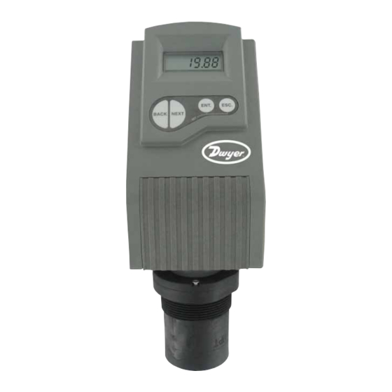
Table of Contents Table of Figures Chapter 1. Introduction Figure 1: Front and Side View ......... .2 Specifications . -
Page 3: Chapter 1. Introduction
Chapter 1: Introduction SPECIFICATIONS The UL is an ultrasonic, continuous-level measurement gage. The unit is available Service: ULB: Bulk solids, ULF: Compatible liquids. in two separate series: The Series ULB for solids and the Series ULF for fluids. Wetted Materials: Sensor: Polypropylene, Acoustic Window: ECTFE. Ranges: (see “Measuring Ranges”). -
Page 4: Chapter 2. Installation
Chapter 2: Installing the Unit Installing the Unit on Threaded Flange/Thread-Free Flange The unit is available in 2˝ NPT or 2˝ BSP (upon request). Precautions • Ensure that the unit is mounted in an area that meets the stated temperature, The unit can be installed with threaded-flange mounting or with thread-free flange pressure and technical specifications. -
Page 5: Installing The Unit Via Extension Pipes
Installing the Unit Via Extension Pipes Non-Intrinsically Safe Connections If the level of the measured surface falls within the dead-zone area, you should use an extension pipe to mount the unit. When using an extension pipe, ensure that: • The sensor is positioned in the center of the pipe. •... -
Page 6: Series Ul Functions
Chapter 3: Setting Up and Calibrating the Unit Using Series UL Functions This chapter explains how to set up and calibrate the unit for accurate The LCD display screen, functioning in "normal" mode, provides continuously measurement monitoring. updated measurement readings. The display screen is also used to view the The unit is supplied with preprogrammed default settings, making it ready for menu options, function settings and data values, accessed by using the function immediate operation. -
Page 7: Resetting The Unit
NOTE: If an error message appears, press the ESC button to return to the main menu. Defining Interfering Signals Values are displayed in feet and inches or meters and centimeters (model The Pr03 function enables you to locate and store up to six interfering signals (false dependent). -
Page 8: Configuring 4 Ma Current Output
Configuring 4 mA Current Output Configuring 20 mA Current Output Pr04 function enables you to enter values to be used as the 4 mA mark for remote The Pr05 function enables you to enter values to be used as the 20 mA mark for monitoring. -
Page 9: Selecting Low/High Dynamic Speed
To Define a Working Area: Selecting Low/High Dynamic Speed (ULF Series Only) Press/Action Display Explanation The Pr06 function enables you to choose the required speed level. There are two Required menu selection. settings available: • SE 0: Low dynamic mode (default setting). This mode provides slower readings with a greater degree of accuracy (rate of up to 31˝/80 cm per min). -
Page 10: Entering Factor For Gas Compensation
Verifying the Version Number method). Add or reduce 0.01 to calibrate the factor figure already entered. In addition to the functions described, you can verify the UL series version Updated on-screen results may take a few seconds to appear. number. -
Page 11: Defining 22 Ma Signal Error Messages
Defining 22 mA Signal Error Messages Chapter 4: Open Channels (ULF) The unit allows you to define if the following signal error indications: Near Zone and This section describes how to set flow measurement parameters for open channels Lost Echo, will be active when the current output reaches 22 mA. The default and explains the flume/weir codes methodology used when setting up flow setting enables 22 mA analog current and error messages to appear on its LCD measurements. -
Page 12: Flume/Weir Types
Flume/Weir Types This is the first value (X) entered for the Pr00 function. The following flume/weir types are available both in European and American standard: European Standard American Standard Type (X) Pages 11-13 Pages 13-14 Rectangular Suppressed Rectangular Suppressed Sharp- Sharp-Crested Weir, Page 11 Crested Weir, Page 13 Rectangular Contracted Sharp-... -
Page 13: Khafagi-Venturi Flume (Type 5)
Khafagi-Venturi Flume (Type 5) Palmer Bowlus Flume Trapezoidal Throat Cross-Selection (Type 7) Code (YY) Flume Type b0 (cm) Code (YY) Conduit Diameter (in) D QV 302 QV 303 QV 304 QV 305 QV 306 QV 308 QV 310 QV 313 QV 316 Figure 15: Khafagi-Venturi Flume Figure 17: Palmer Bowlus Flume Trapezoidal Throat Cross-Selection... -
Page 14: Neyrpic Venturi Flume/Long-Base Weir (Type 9)
Neyrpic Venturi Flume/Long-Base Weir (Type 9) Rectangular Contracted Sharp-Crested Weir (Type 2) Code (YY) Venturi Flume Type Code (YY) Crest Length (in) 1253AX 12.00 1253AY 18.00 1253AZ 24.00 1253A 30.00 1253B 36.00 1253C 48.00 1253D 60.00 1253E 72.00 1253F 96.00 Figure 19: Neyrpic Venturi Flume Code (YY) Long Base Weir Type... -
Page 15: Parshall Flume (Type 5)
Parshall Flume (Type 5) H Flume (Type 7) Code (YY) Flume Size (in) Measurement Point (in) Code (YY) Throat Width (in) 1.96 2.75 3.54 5.51 7.08 9.05 11.02 16.14 Figure 27: H Flume Leopold-Lagco Flume (Type 8) Code (YY) Crest Length (in) Figure 25: Parshall Flume Palmer Bowlus Flume Trapezoidal Throat Cross-Selection (Type 6) Code (YY) -
Page 16: Chapter 5 Troubleshooting
Chapter 5 Troubleshooting 22 mA Signal Error Messages This chapter describes how to resolve problems that may occur when calibrating The following list of messages will appear on the display and coincides with a 22 the unit as follows: mA analog current error output signal (when the error signals messages are enables): Error Description... -
Page 17: Appendix A - Gas Factor Table
Appendix A Appendix B Gas Factor Table Installation Tips The following table contains 32 different types of gasses and their factor for 1) Choosing Location compensating the sound velocity: Distance to tank walls Must Be At least 19.69˝ (50 cm) from Factor Symbol walls + 3.94˝/3.28 ft (10 cm/1... -
Page 18: Figure 29: Nomenclature
Appendix C Figure 29: Nomenclature Page 17 ©Copyright 2010 Dwyer Instruments, Inc. Printed in U.S.A. 12/10 FR# R4-443852-00 DWYER INSTRUMENTS, INC. Phone: 219/879-8000 www.dwyer-inst.com P.O. BOX 373 • MICHIGAN CITY, INDIANA 46361, U.S.A. Fax: 219/872-9057 e-mail: info@dwyer-inst.com...
Need help?
Do you have a question about the UL series and is the answer not in the manual?
Questions and answers