Advertisement
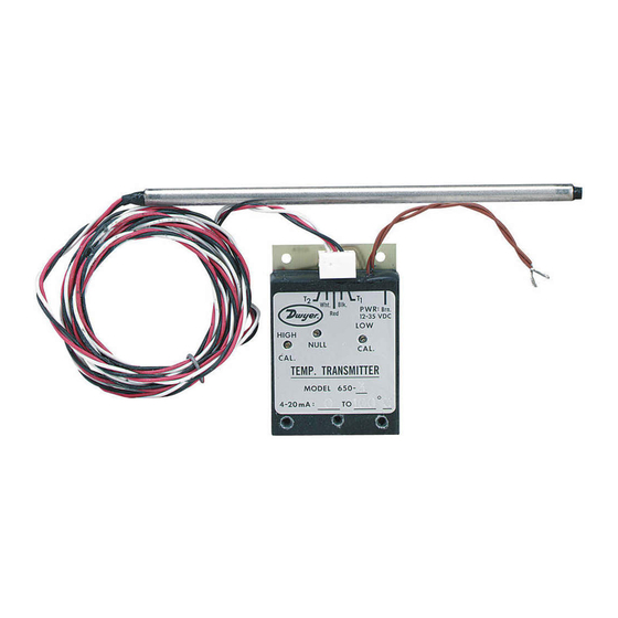
The Dwyer Series 650 Temperature Transmitter provides a 4-20 mA
control signal output which varies in linear relationship to the
temperature of the silicon transducer in the sensing probe. The low cost
and small size of the Series 650 Temperature Transmitter make it ideal
for a wide variety of multipoint temperature monitoring applications. Non-
polarized power connections simplify electrical connection to any power
source providing 12 to 35 volts DC.
Models are stocked in three popular ranges, all with factory calibration
within 0.3% and linearity within 0.25% of span. Units can be field
calibrated to limits shown in chart at right. See calibration instructions on
page 2 for procedure.
INSTALLATION
Location: Select a location where the temperature of the unit will remain
between 0° and 70°C. The location must also be within the 7 foot length
of the sensing probe cable. The power supply and the receiving control
device can be located up to several hundred feet from the transmitter
itself.
Position: The Series 650 can be mounted in any position. It is advisable
to keep the adjustment screws and connector plug easily accessible for
future re-calibration or service.
Mounting: The Series 650 electronics package can be attached to
mounting surface by means of the five holes provided. Refer to the
dimensional drawing, Figure A for these hole spacings. The small size of
the transmitter electronics package allows it to be mounted inside a
standard household single gang electrical box, if preferred. When
mounting the temperature sensing probe in a sheet metal duct or on
other thin walled enclosures, the use of the Dwyer Model A-325 Duct
Mounting Kit is recommended. Refer to Figure B for details on this
45/64
[17.86]
1-53/64
[46.43]
19/32
[15.08]
5/16 [7.94]
DWYER INSTRUMENTS, INC.
P.O. BOX 373 • MICHIGAN CITY, INDIANA 46360, U.S.A.
Series 650 Temperature Transmitter
Specifications - Installation and Operating Instructions
13/64
Ø1/8 [3.18]
[5.16]
13/64 [5.16]
3/16 [4.76]
7/32 [5.56]
2-5/8 [66.68]
FIGURE A
1-53/64
[46.43]
19/32
[15.08]
SPECIFICATIONS
Power Supply: 12 to 35 volts DC.
Output Signal: 4 to 20 mA DC.
Voltage Stability: Output error less than 0.01% of span over the speci-
fied supply voltage range.
Linearity: Within 0.25% of span.
Initial Calibration: Within 0.3% of span at 20°C/68°F ambient.
Thermal Drift: Less than 0.5% of span over ambient temperature range
of 0 to 50°C, 32 to 122°F.
Ambient Operating Temperature (Electronics): 0 to 70°C, 32 to 158°F.
Maximum Temperature (Probe): 204°C/400°F.
Probe Construction: 6˝ long, 0.25˝ O.D., Type 304 SS.
Note: Special factory calibrated ranges are available within the limits of - 55°C and
+ 180°C. Contact factory with specifications for price and availability.
SERIES 650 TRANSMITTER MODELS & RANGES
FACTORY CALIBRATION
MODEL
RANGE AS
NUMBER
STOCKED
650-1
-23° to + 10°C
650-2
-7° to + 49°C
650-3
0° to + 100°C
To achieve TOTAL RANGE LIMITS above (with 4 to 20 mA output), the
lowest temperature being sensed (at 4 mA) must be between the
minimum and maximum values under LOW END LIMITS.
arrangement. Other customer designed probe mounting configurations
can be used as long as the tip of the sensing probe is in the space where
temperature is to be controlled.
1-5/16
[33.34]
Phone: 219/879-8000
Fax: 219/872-9057
Ø1/8 [3.18]
45/64
[17.86]
5/16 [7.94]
3/16 [4.76]
7/32 [5.56]
2-5/8 [66.68]
FIELD CALIBRATION
TOTAL RANGE LIMITS
MAX. SPAN
MIN. SPAN
24°C
48°C
150°C
37°C
37°C
150°C
A-325 DUCT MOUNTING KIT
A-345 FLANGE W/GASKET
650 PROBE
[2]#10X1 TYPE A
PAN HD. SHT. MTL.SC
DUCT
FIGURE B
www.dwyer-inst.com
e-mail: info@dwyermail.com
Bulletin E-62
13/64
[5.16]
1-5/16
[33.34]
13/64 [5.16]
LOW END LIMITS
MIN.
MAX.
- 32°C
- 14°C
- 12°C
+ 6°C
- 12°C
+ 6°C
Advertisement
Table of Contents

Subscribe to Our Youtube Channel
Related Manuals for Dwyer Instruments 650 Series


Summary of Contents for Dwyer Instruments 650 Series
- Page 1 650 PROBE 13/64 [5.16] 3/16 [4.76] [2]#10X1 TYPE A 7/32 [5.56] PAN HD. SHT. MTL.SC DUCT 2-5/8 [66.68] FIGURE A FIGURE B DWYER INSTRUMENTS, INC. Phone: 219/879-8000 www.dwyer-inst.com P.O. BOX 373 • MICHIGAN CITY, INDIANA 46360, U.S.A. Fax: 219/872-9057 e-mail: info@dwyermail.com...
- Page 2 Readout should be returned to the manufacturer if service is required. monitor water temperature. Refer to the A-701 instruction sheet. Note: Interchanging sensing probes requires recalibration to maintain published accuracies. ©Copyright 2014 Dwyer Instruments, Inc. Printed in U.S.A. 7/14 FR# R0-440495-00 Rev.2 DWYER INSTRUMENTS, INC. Phone: 219/879-8000 www.dwyer-inst.com...
Need help?
Do you have a question about the 650 Series and is the answer not in the manual?
Questions and answers