Table of Contents
Advertisement
Quick Links
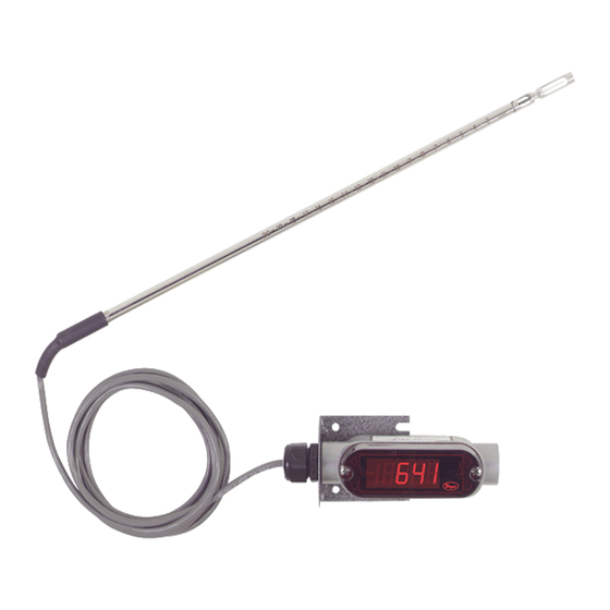
The Series 641RM Air Velocity Transmitter uses a heated
mass flow sensor technology. It has 8 user selectable
ranges from 250 FPM to 15000 FPM with corresponding
metric ranges of 1.25 MPS to 75 MPS. The Series 641RM
Air Velocity Transmitter provides an isolated 4-20 mA out-
put proportional to the velocity. With the optional 1/2˝ 4-1/2
digit LED display, the Series 641RM Air Velocity Transmitter
will provide a highly visible local readout of the velocity.
INSTALLATION
Location: Select a location where the temperature will be
within 32 to 140°F (0 to 60°C) to mount the enclosure. The
transmitter may be located any distance from the receiver
provided that the total loop resistance does not exceed 600
ohms. The probe should be located where conditions are
representative of the overall environment being monitored.
Avoid locations where turbulence, stagnation, or rapidly
fluctuating velocities or temperatures are present as these
conditions may affect the readings. The filter setting may be
used to average velocity readings in turbulent conditions.
Position: The transmitter is not position sensitive and may
be mounted in any orientation.
Probe Orientation: Dots on the probe indicate the direc-
tion of the calibrated airflow. Align these dots toward the
source of the process air.
Airflow: The Series 641RM Air Velocity Transmitter is
intended for use with clean dry air. Particulates in the air
may cause sensor damage. Dust accumulation may impair
the velocity measurement and will require probe cleaning.
TO READ DISPLAY UNIT MUST BE MOUNTED HORIZONTALLY
AS SHOWN ABOVE. DISPLAY CAN BE TURNED 180° SO CON-
DUIT OPENING CAN BE POSITIONED TO THE RIGHT OR LEFT.
DWYER INSTRUMENTS, INC.
1.800.561.8187
P.O. BOX 373 • MICHIGAN CITY, INDIANA 46361, U.S.A.
Series 641RM Air Velocity Transmitter
Specifications - Installation and Operating Instructions
1/2 NPT
1-39/64
[40.88]
Phone: 219/879-8000
Fax: 219/872-9057
www.
.com
1-5/8 [41.28] WITH LED
1-3/32 [27.78] WITHOUT LED
4-31/32
[126.21]
Ø5/16
[Ø7.94]
14-21/64
[53.07]
Ø13/64
FOR A STANDARD 12˝ PROBE
[Ø5.16]
31/64
1-25/32
[12.30]
[45.24]
SPECIFICATIONS
Service: Air and compatible, non-combustible gases.
Accuracy:
3% FS Process gas: 32 to 122°F (0 to 50°C).
4% FS Process gas: -40 to 32°F & 122 to 212°F
(-40 to 0°C & 50 to 100°C).
Response Time: Flow: 1.5 seconds to 95% of final value (out-
put filter set to minimum).
Temperature Limits: Process: -40 to 212°F (-40 to 100°C).
Ambient: 32 to 140°F (0 to 60°C).
Pressure Limit: 100 psi (6.89 bar) maximum.
Humidity Limit: Non-Condensing.
Power Requirements:
12–35 VDC, 10–16 VAC.
Output Signal:
4-20 mA, isolated 24V source, 3 or 4-wire
connection.
Output Filter: Selectable 0.5 –15 (seconds).
Loop Resistance: 600 ohms max.
Current Consumption: 300 mA max.
Electrical Connections: Screw terminal.
Mounting Orientation: Unit not position sensitive. Probe must
be aligned with airflow.
Weight: 13.2 oz (374.26 g).
Cable Length: 6 ft (1.82 m).
Probe Length: 12˝ (30.48 cm) standard.
Probe Diameter: 5/16˝ (0.79 cm).
OPTIONAL DISPLAY VERSION:
Display: 4-1/2 digit 1/2˝ Red LED.
Resolution: 1 FPM, 0.01 MPS
(10 FPM @ 10,000 and 15,000 FPM ranges).
Weight: 13.9 oz (394.16 g).
Agency Approvals: CE
The following standards were used for CE approval:
IEC 61000-4-2: 2001
IEC 61000-4-3: 2002
IEC 61000-4-4: 1995
IEC 61000-4-5: 2001
IEC 61000-4-6: 2003
IEC 55011: 1998
IEC 61326: 2002
89/336/EEC EMC Directive
www.dwyer-inst.com
information@itm.com
e-mail: info@dwyer-inst.com
Bulletin E-66-RM
43/64
[17.07]
6 FT
[152.40]
Advertisement
Table of Contents

Related Manuals for Dwyer Instruments 641RM Series


Summary of Contents for Dwyer Instruments 641RM Series
- Page 1 AS SHOWN ABOVE. DISPLAY CAN BE TURNED 180° SO CON- IEC 55011: 1998 DUIT OPENING CAN BE POSITIONED TO THE RIGHT OR LEFT. IEC 61326: 2002 89/336/EEC EMC Directive DWYER INSTRUMENTS, INC. Phone: 219/879-8000 www.dwyer-inst.com 1.800.561.8187 information@itm.com P.O. BOX 373 • MICHIGAN CITY, INDIANA 46361, U.S.A.
- Page 2 Page 2 NOTE: Where conduit connections are not made, a 1/2˝ CAUTION: Do not use transformers with a secondary volt- NPT cable seal should be used to prevent contaminants age rating greater than 16 VAC RMS. from entering the case. Where conduit connections are made, make sure that any possible condensation within the Wire Type and Length —...
- Page 3 Page 3 Two buttons and a potentiometer control the setup process. Range Selection The SELECT button is used to scroll between the setup The range selection allows you to select one of eight ranges parameters. in either feet per minute (FPM) or meters per second (MPS). The ENTER button allows access to each parameter for adjustment.
- Page 4 Because of specialized computer instrumentation required, each other. Press SELECT until the 4 mA LED indicator is these units must be returned to Dwyer Instruments for fac- illuminated then press ENTER. The milliammeter will now tory calibration. Contact customer service to receive a read approximately 4.0 mA.
Need help?
Do you have a question about the 641RM Series and is the answer not in the manual?
Questions and answers