Table of Contents
Advertisement
Advertisement
Table of Contents

Subscribe to Our Youtube Channel
Related Manuals for Berkeley Varitronics Systems wolfhound pro


Summary of Contents for Berkeley Varitronics Systems wolfhound pro
- Page 1 User’s manual version 1.6 ...
-
Page 2: Table Of Contents
Contents ............................ 2 Table of Contents INTRODUCTION .......................... 4 Wolfhound-PRO UNIT DESCRIPTION .................... 7 Items Supplied ............................5 Organic Light Emitting Diode (OLED) ....................... 9 Higher-Level Menu Screens ........................10 MAIN MENU Screen (highest-level menu) ..................10 MEASUREMENTS Screen ........................11 Phone Detection Mode ........................11 Direction Finding Mode ........................14 Frequency Discriminator Mode ......................15 Direction Finding Scale ........................16 Threshold Marker Setting ........................16 Reset Max Bars ..........................17 DECT 6.0 Detection Mode ........................17 SETUP ............................ 1 8 Antenna Connection ..........................19 Attachment of Omnidirectional Antenna ..................19 Attachment of Direction Finding (DF) Antenna ................. 19 Activating Accessories (Sound/Vibrater/Laser) ..................20 Adjusting Volume ..........................21 Selecting Frequency Band ........................22 Adding Attenuation (if necessary) ..................... 23... - Page 3 Information Screen ..........................23 Loading Default Parameters ........................24 OPERATION & USE ........................ 2 5 Resetting the Maximum-Hold Marker ....................25 Antennas ..............................25 General Guidelines for Good Signal Reception ..................26 Monitoring Cell Phone Use in Real-Time ................... 26 Monitoring Coarse Scale Maximum Hold ..................26 Using Wolfhound-PRO Unit with the Omnidirectional Antenna ............26 Using the Wolfhound-PRO Unit with the Direction Finding (DF) Antenna…………………………………….…… 26 Method 1: Maximizing Signal Along the Same LOP ................28 Method 2: “Triangulate” with Two (or more) LOPs ................29 MAINTENANCE and TROUBLESHOOTING .................. 3 0 Charging Batteries ............................. 30 Appendix 1: Synopsis for the optional Wolfhound-PRO PC Software………………………………………..……………31 Wolfhound-PRO Windows Software……………………………………………………………………………………………………. 32 Introduction…………………………………….…………………………………….………………………….………………………………… 32 Installation of Software………….…………………………………….…………………………………….……………………………… 32 Getting Started…………………………………………………….…………………………………….…………………………………….… 32 Realtime………….…………………………………….…………………………………….…………………………………….………………… 34 Statistics……………………………………………….…………………………………….…………………………………….………………… 35 Settings……………..…………………………………….…………………………………….…………………………………….……………… 36 Help………………….…………………………………….…………………………………….…………………………………….……………… 39...
-
Page 4: Introduction
INTRODUCTION The Wolfhound-PRO cell detector uses a narrow-band/high-selectivity receiver controlled by an on-board processor. The Wolfhound-PRO receiver has a resolution bandwidth of 4 MHz and uses a square-law detector. The receiver can be set to scan multiple up-link frequency bands assigned to North America, the European Union, Asia and Australia, as listed in Table 1: A A i i r r I I n n t t e e r r f f a a c c e e U U p p - - L L i i n n k k F F r r e e q q u u e e n n c c y y... - Page 5 The receiver detector output is used to drive one or more of the following indicators: height of coarse and fine bar charts in the OLED display 2. pulsing rate of Laser (optional accessory mounted on DF antenna assembly) 3. pulsing rate of Sound Alert (speaker or ear bud) 4.
- Page 6 Items Supplied The standard package (as shipped) includes the Wolfhound-PRO unit and accessories, including a carrying case as seen in Figure 2: Wolfhound-PRO Cell Detector unit Operators manual VELCRO hand strap Ear bud External AC Power Charger Omnidirectional monopole antenna Direction Finding (DF) Antenna assembly Mini USB cable Pelican® briefcase (black with secure lock and keys) Figure 2. Wolfhound-PRO unit and accessories Optionally, the following items are also available: Green Laser module (mounted on DF antenna assembly) PC Software package (for real-time monitoring, data logging and report generation) See Appendix 1 below for a synopsis of the functions performed by this software.
-
Page 7: Wolfhound-Pro Unit Description
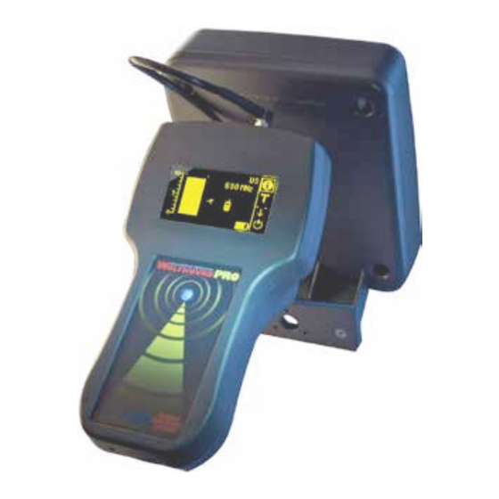
Wolfhound-PRO UNIT DESCRIPTION Wolfhound-PRO (trackball model) unit appear in Figure 3. The unit has an OLED, navigation trackball, five electrical interfaces and an LED as listed below (see also arrows 1, 2, 3, 6, 7 and 8 in Figure 3): 1. Antenna port 2. Audio (ear bud) jack 3. DC Power jack 4. Liquid Crystal Display (OLED) 5. Trackball (roll for 2D cursor navigation/press down for selecting) 6. Laser jack 7. Mini USB jack 8. Battery status LED (Red) Figure 3a. The Wolfhound-PRO Unit, Controls, Indicators and Interfaces... - Page 8 Note: Some Wolfhound-Pro models utilize a single trackball for menu navigation and control while other Wolfhound-Pro models use a 5-button layout for navigation. Both units are identical in performance and features leaving the appearance and physical navigation as the only difference between the two models. 1. Navigate / adjust up menu 2. Navigate / adjust to the right 3. Navigate / adjust down menu 4. Navigate / adjust to the left 5. Select or deselect highlighted icon / Power ON unit Figure 4b. The Wolfhound-PRO Keypad Pushbutton Navigation Controls...
-
Page 9: Organic Light Emitting Diode (Oled)
Organic Light Emitting Diode (OLED) The Wolfhound-PRO unit can be turned on by holding down the trackball or black center pushbutton (see arrow 5 in Figure 3) at least for about a second. When the unit is powered, the amber monochrome OLED will display one of the three measurement screens (Phone Detection, Direction Finding or DECT 6.0 Detection) from which the unit was turned off. Thus, if the unit was being used in the Direction Finding mode just before powering off, next time it is powered on the OLED will display the Direction Finding screen in Figure 4: Figure 4. OLED displaying the Direction Finding Screen... -
Page 10: Measurements Screen
Clicking “Back” in Figure 5 or in any other screen where “Back” appears will take the user to the next higher level menu or screen. The first four items in the MAIN MENU (i.e., Measurements, Effect Options, Settings and Information) are discussed next : MEASUREMENTS Screen Clicking on “Measurements” from the MAIN MENU (Figure 5) will yield the MEASUREMENTS Menu: Figure 6. MEASUREMENTS Menu Screen This menu allows the user to enter one of the three modes of real-time monitoring of the Wolfhound- PRO unit: Phone Detection Mode In this mode (see Figure 7), the Wolfhound-PRO will detect the use of one or more cell phones while monitoring the relative strength of the source signal(s) and frequencies using the Omnidirectional antenna. The frequency band needs to be selected via the BAND SELECTION screen. The frequency indication corresponds to the strongest signal detected in the selected frequency band, using a coarse... - Page 11 Typical Screen Figure 8. Typical Screen Icons The screen and icons shown is the typical Direction Finding screen but shares many functions and icons of most other measurement screens in the Wolfhound-PRO. Coarse Bar Chart: Indicates instantaneous signal strength on a scale of 0 to 10. Maximum hold indication provided by the two dashes at each side of bar-chart. “T” Threshold Setting marker: Threshold setting is adjusted by pressing the ball down on the icon on the right (see Figure 13), then rolling the ball (up or down) to the desired level with respect to the bar chart scale to the left, then clicking the ball down to lock marker setting. This setting controls both the Frequency Field and Cell Phone icon indicators (arrows 4 and 5). Direction Finding Features Toggle: This icon will only display when in the Direction Finding selection in the Measurements menu. Selecting this icon and toggle through the following modes: Threshold (T), Reset Maximum Hold (arrow pointing down), Frequency Discriminator Mode (single cellphone), Scan All Mode (3 cell phones), Direction Finding Mode (scale). Once...
- Page 12 you see the function you like, select that icon and push in the black center pushbutton or trackball (model dependent) to select that function. Direction Finding Scale: This vertical scale only appears when Wolfhound-PRO is in the Direction Finding mode. This scale measures signal strength like the scale to the left of it but at a finer resolution making it useful for sensitive direction finding. Cell Phone icon: This fixed icon turns on when any signal level in the frequency band exceeds the threshold marker setting. Geographic Region: This field indicates one of multiple possible frequency band settings . Information Icon: Selecting this icon brings back the MAIN MENU screen Direction Finding Mode: Selecting this icon puts the Wolfhound-PRO into Direction Finding Mode. The more granular RSSI scale on the right will appear in this mode.
- Page 13 Direction Finding Icons These are icons appear in the direction finding mode and their functions are all useful when performing direction finding: Select this icon to toggle through the following functions in the Direction Finding Menu: Select this icon to set Threshold. The icon will change to for adjustment. Lower or raise the Threshold. Push the trackball or black center pushbutton to select new level. Select this icon to reset maximum signal detected bar. Select this icon to remove the strongest signal from the list of detected phones. Select this icon to “see” all cell phones detected. Select this icon to enter the Direction Finding measurement mode.
-
Page 14: Direction Finding Mode
Direction Finding Modes This mode of measurement allows the user to determine the Line of Position of a radiating cell phone (or, the direction from which the cell phone is radiating), as well as detecting the cell phone signal (see Figure 9). The frequency band needs to be selected (US, EU, AU,..) via the BAND SELECTION screen. Figure 9. The Direction Finding Modes Within the Direction Finding mode there are two different features that allow the user to detect cell phones with greater accuracy. These features can be found by highlighting the spinning wheel icon and selecting it. Here are the two different features in the Direction Finding mode followed by a brief description for each one:... -
Page 15: Frequency Discriminator Mode
Frequency Discriminator Mode: Figure 9. Frequency Discriminator Mode The Frequency Discriminator mode allows the user to remove the strongest signal of a cell phone from a particular frequency band. This application is helpful when a known cell phone is detected and needs to be filtered out by the Wolfhound PRO so the user can find other hidden cell phones in the same frequency band. When this mode is activated the band selection will display “-“ where the frequency just appeared. To deactivate the Frequency Discriminator mode highlight the icon shown in figure 11 and select it. The icon shown in figure 12 will appear and the band selection will be displayed. Frequency Discriminator Mode: Figure 11. Frequency Discriminator Mode... -
Page 16: Direction Finding Scale
Direction Finding Scale: Figure 12. Direction Finding Scale When the Direction Finding mode is activated, a graph appears allowing the user to see greater granularity of the detected cell phone signal. It is recommended to use this mode with the Direction Finding antenna attached to the Wolfhound PRO to uncover hidden cell phones. As the signal increases or decreases in the graph to the right the user can determine the direction of the cell phone. For more details on setting up the Direction Finding Antenna refer to Attachment of Direction Finding Antenna. There is also the Threshold Marker and the Reset Max Bars icons that are found using the spinning wheel icon. Threshold Marker Setting: Figure 13. Threshold Marker... -
Page 17: Reset Max Bars
The Threshold Marker Setting allows the user to set a line anywhere along the scale on the left. Should the Wolfhound-PRO detect a signal that exceeds that threshold, the user will be alerted with one or more alerts (see Activating Accessories for information on this). To change the threshold marker, highlight the T icon and select it. The T icon located near the scale can now be modified up or down using the trackball or up/down buttons on the keypad (model dependent). Press the trackball or keypad center pushbutton again to set the desired level. Reset Max Bars: Figure 14. Reset Max Bars The Reset Max Bars mode is activated when the user highlights the spinning wheel icon and selects until the down arrow icon appears as shown in Figure 14. Once a cell phone is detected and the bar appears, the markers will move to the maximum level detected and remain there. This mode is helpful when the user is busy while cell phone activity is occurring. To set the markers to zero, select the down arrow icon while it is highlighted. -
Page 18: Dect 6.0 Detection Mode
DECT 6.0 Detection Mode DECT 6.0 cordless phone monitoring is initiated from the MEASUREMENTS screen, regardless of frequency band selection. The various fields in the DECT 6.0 Detection screen are identical to those of the Direction Finding screen with the exception of the Geographic Region field as follows (Figure 7): Figure 15. DECT 6.0 Detection Mode SETUP Setup of the unit before use requires the completion of the following sequence of steps: 1. attaching one of the provided antennas to the unit as appropriate (Omnidirectional antenna for detecting/monitoring, DF antenna for locating) 2. powering up the unit by pushing in trackball or center keypad pushbutton 3. activating accessories (Sound, Vibrator, Laser) as needed 4. adjusting Volume (if Sound was activated) 5. selecting the frequency band (US or EU) 6. adding attenuation if necessary (for strong in-band signals) Each of these steps are discussed in greater detail below: Powering the unit before connecting the antenna should be avoided. -
Page 19: Antenna Connection
Antenna Connection The antenna port (SMA-jack) is located just below the OLED when the unit is held in the normal orientation (arrow (1) in Figure 3). Either one of the two antennas (Omnidirectional or Direction Finding) will interface with this connector, as follows: Attachment of Omnidirectional Antenna Simply screw the antenna connector at the base of the antenna to the antenna jack on the unit (see left side of Figure 1). Attachment of Direction Finding (DF) Antenna Attaching the DF antenna to the unit is done in three steps, as follows: 1) attach bracket to the DF antenna flange using the two thumb screws 2) attach the DF antenna assembly RF and Laser connectors to the Antenna and Laser jacks respectively (see (A) left and right sides in Figure 16). Use of wrench to tighten antenna connector may damage unit. Finger-tight only -- DO NOT use a wrench. -
Page 20: Activating Accessories (Sound/Vibrater/Laser)
CAUTION: The antenna connector should be hand-tightened only to the unit SMA port. Use of a wrench for this purpose will result in damage to the unit housing and/or the connector, hence null the product warranty. Application of stress to the DF Antenna should also be avoided to preclude permanent damage to Unit and/or the DF Antenna assembly. Powering Up Unit The unit is powered up by pushing in the trackball or black center pushbutton (model dependent) for at least 1 second. When powered, the amber monochrome OLED will display one of the three measurement screens (Phone Detection, Direction Finding or DECT 6.0 Detection) from which the unit was turned off the last time it was used. -
Page 21: Adjusting Volume
18: Figure 18. EFFECTS ON / OFF menu Check the desired fields (Sound, Vibrator, Laser as needed) by clicking the ball, then select “Back” to return to the “EFFECT OPTIONS” screen (Figure 17). The behavior of these accessories as a function of the detected signal strength will be as follows: Laser: the laser starts pulsing at a constant rate when the signal level exceeds the Threshold level. the duty cycle of the laser pulse increases with increasing signal level but the pulse rate (or period of pulse) stays constant. Sound: when the signal level exceeds the Threshold level, sound alarm starts beeping. Beeping rate increases with increasing signal level. Vibrator: the Vibrator alert will go off when signal level exceeds the Threshold level. The vibrator alert will operate intermittently at a constant rate and duty cycle independent of detected signal level, as long as it exceeds the threshold setting. -
Page 22: Selecting Frequency Band
4. return to “EFFECT OPTIONS” screen by clicking on the left-arrow icon at top right corner 5. return to “MAIN MENU” screen by clicking on “Back” Selecting Frequency Band Starting from MAIN MENU, select “Settings” to enter the “SETTINGS” screen. Then select “Band Selection” to enter the “BAND SELECTION” screen (Figure 19). Figure 19. BAND SELECTION screens Adding Attenuation (if necessary) The purpose of this screen is to allow the user introduce variable attenuation between the antenna input port and the input to the receiver to avoid overloading the highly sensitive receiver. This can be encountered when the Wolfhound-PRO unit is deployed near cell towers or other in-band RF sources. To do this, select “Settings” from the MAIN MENU screen to get the “SETTINGS” screen, then select “Attenuation” to enter the ATTENUATION screen (see Figure 20):... -
Page 23: Information Screen
Figure 20. ATTENUATION screen (set to ~ 10dB) The attenuation level is adjusted by clicking on the second icon from the upper right corner in Figure 20, then rolling the ball to move the “elevator” up to increase attenuation while simultaneously observing the signal level decreasing on the coarse bar chart and scale on the left side of the screen. The number immediately to the right of the elevator icon represents the approximate level of attenuation in dB as it is varied over the interval of 0 to 30. The maximum attenuation attainable in this manner is ~ 30 dB, corresponding to about 5 divisions on the coarse signal scale. Information Screen The Information screen provides crucial information about the Wolfhound-PRO unit battery status and the unit firmware version. To access this screen, select “information” from the MAIN MENU to produce the INFORMATION screen seen in Figure 21: Figure 21. INFORMATION screen When the first menu item (Battery Status) is clicked, it will produce the BATTERY STATUS screen with unit-specific time-dependent battery information as seen in Figure 22:... -
Page 24: Loading Default Parameters
Figure 22. BATTERY STATUS screen When the second menu item (Product Info) is clicked, the PRODUCT INFO screen appears with the unit's firmware version and serial number (see Figure 23): Figure 23. PRODUCT INFO screen (representative) On the actual PRODUCT INFO screen of the unit, the “SN:” characters shall be followed by the six-digit serial number of the unit appearing on the serial number label (with the BVS logo) pasted to the side of the unit. Both of these screens (Figures 22 and 23) are exited by clicking on the left-arrow icon on the top right corner of the screens. Loading Default Parameters When the unit is powered up it will recall parameter values (signal threshold level, attenuation, volume, all accessories off, US frequency bands, Phone Detection mode) used before it was turned off. However, at any time the user can re-load default parameters (i.e., parameter values set by BVS before the unit was shipped to the customer) to the Wolfhound-PRO unit by selecting and clicking on “Load Defaults” in the SETTINGS screen (Figure 24):... -
Page 25: Operation & Use
Figure 24. selecting “Load Defaults” from the SETTINGS screen OPERATION & USE The Wolfhound-PRO unit is turned on by pressing and holding in the trackball or keypad center pushbutton for at least one second. The unit is turned off by selecting the power-off icon in any one of the following four screens: 1. Phone Detection screen (Figure 7) 2. Direction Finding screen (Figure 8) 3. DECT 6.0 detection screen (Figure 14) 4. BATTERY STATUS screen (Figure 22) The power-off icon is located at the right-hand lower corner of each of these screens. Resetting the Maximum-Hold Marker While in any one of the three monitoring modes (Phone Detection, Direction Finding or DECT 6.0 Detection), clicking on the down arrow icon “-↓-” (the third icon from top on the right-hand side of screen) will reset the maximum-hold marker “- -” (i.e., two dashes one on each side of coarse bar- chart) to the instantaneous signal level on the coarse bar chart. In the absence of a detected signal, the... -
Page 26: General Guidelines For Good Signal Reception
connecting the antenna to the source is approximately perpendicular to the plane defined by the flat face of the DF antenna panel. Sources falling to the rear of the plane of the DF antenna panel will produce substantially diminished antenna output. To help the user maintain proper orientation of the DF antenna, a pulsed green Laser is integrated into the DF antenna. The Laser is mounted on the lower flange of the DF antenna assembly. The duty cycle of the pulsed Laser increases with increasing level of the detected signal. General Guidelines for Good Signal Reception The Wolfhound-PRO unit should be kept at about waist to head height from the floor, and away from walls and obstructions for proper performance. For the same reason, keep the Wolfhound-PRO unit at... -
Page 27: Using The Wolfhound-Pro Unit With The Direction Finding (Df) Antenna
For best performance, the Omnidirectional antenna should be oriented vertical (tip of antenna pointing to ceiling or up) with respect to the floor plane . Using the Wolfhound-PRO Unit with the Direction Finding (DF) Antenna The DF antenna enables the user to determine the direction in the horizontal (or floor) plane along which the detected signal is maximum. When it is practical or appropriate, the Green Laser (mounted on the DF Antenna assembly) may be deployed for assisting the user for aiming the DF antenna to potential sources. The imaginary line along which the signal is maximum is called a Line of Position. After an initial Line Of Position (LOP) is established by a 360 degree sweep of the unit/DF antenna, the user takes a few steps in the LOP direction and then re-confirms the new LOP orientation by sweeping the unit/DF antenna back and forth about the initial LOP (see Figure 25), while observing the receiver... -
Page 28: Method 1: Maximizing Signal Along The Same Lop
Method 1: Maximizing Signal Along the Same LOP This method is based on approaching the source along the same LOP (see Figure 21) to maximize receiver output at successive points towards the source. source Point 3 Point 2 Point 1 Figure 26. Method 1: Pursuing Source Along the Same LOP For Method 1 use the following sequence: 1. Keep the DF antenna level by observing the height of the point at which the laser beam reflects from a wall or other object (or keep the laser beam parallel to the horizontal or floor plane). 2. Sweep the DF antenna in the azimuthal direction, from side to side within an arc of about 90 degrees (i.e., 45 degrees to right, then 45 degrees to left, and repeat…) to determine relative direction for maximum detector output on the DF bar-chart (see arrows 4 and 5 in Figures 8 and 9). -
Page 29: Method 2: "Triangulate" With Two (Or More) Lops
3. While the DF antenna is pointing at the potential source, re-set the Coarse Scale Maximum Hold marker by pressing the “-↓-” button (arrows 1 in Figures 8 and 14). This will make the DF bar- chart read maximum level (i.e. 0 to +1 on the DF Scale”) to help the user make small adjustments to his/her intermediate heading to “lock-in” on the actual orientation of the source. 4. Walking slowly in the same heading, scan the unit again for maximum signal in the same manner, while the signal level registered on the coarse bar chart increases. -
Page 30: Maintenance And Troubleshooting
Once the approximate location is known, Method 1 can be used to “zoom-in” on the source, by maximizing receiver signal level. The following sequence is used: 1. Choose Point 1 and determine LOP1 2. Move away from LOP 1 in the perpendicular direction to Point 2 without getting too close to obstructions and/or walls. At Point 2 determine LOP2. 3. Mentally determine approximate area of intersection for LOP1 and LOP2 within the space monitored. -
Page 31: Appendix 1: Synopsis For The Optional Wolfhound-Pro Pc Software
Appendix 1: Synopsis for the optional Wolfhound-PRO PC Software At a high level, this software allows the Wolfhound-PRO unit outputs to be displayed and monitored on a PC or Laptop screen in real-time, by performing the following functions: - Receives data from Wolfhound-PRO via mini USB port. - Real-Time monitoring. - Alerts when activity is detected above a set threshold. - Reports power level, and at what frequency the alert was triggered. - Alert drops when power falls below drop threshold. - Displays registration, text message, and call alerts. - Logs data to a SQL database. - Reports can be generated from historical data for activity patterns. - Reports can be printed directly. The detailed user manual for this software is included in the Wolfhound-PRO PC Software package available as an optional item. -
Page 32: Wolfhound-Pro Windows Software
WolfHound Pro Windows Software Introduction The WolfHound Pro is a hand-held portable cell phone detector. The WolfHound Pro PC software collects real-time data from the WolfHound when connected via a USB cable. This data is stored and can be retrieved at any time for the display of statistics or generation of printed reports. Installation of Software The software is contained on an SD card. After installation is complete, run the application. If an error occurs when trying to open the database, please change the properties of the shortcut to run in Windows XP compatibility mode. Also, please run the application as administrator. This will help alleviate any security issues with writing to the database. -
Page 33: Getting Started
Getting Started Connect the provided USB cable to the WolfHound Pro and PC. Turn on the WolfHound Pro receiver. Start the WolfHound Pro software. The status window in the upper-right portion of the screen will display messages. If connected properly, the firmware version and serial number of the unit will appear as messages. The real-time display of signal strength will begin to appear. NOTE: The first time the software is run, the user will be requested to enter a registration code. The registration code is provided along with the software. Type in the registration code to unlock the real- time feature of the application. The software will not ask for this information again. Quick Tour The WolfHound Pro has a tab control menu on the left-hand side of the main screen which separates the functionality into main sections. These are: REAL-TIME – Displays information real-time being collected from the WolfHound Pro STATISTICS – Allows the user to review stored information in a graphical format and to then be able to print out the information in a report. The WolfHound Pro also has a menu for Settings and Help along the top edge of the display window. -
Page 34: Realtime
REAL-TIME When real-time mode is selected, data currently being collected by the WolfHound Pro is displayed over time. This is displayed in a temporal graph from right to left. There are approximately 5 reports per second. The signal strength is reported between 0 and 100. When the signal strength goes above the currently set threshold (see SETTINGS) the area under the signal strength will appear red. The area will stay red until the signal strength falls below the threshold again. When the threshold has been eclipsed, counters will be updated. These counters include: REGISTRATIONS TEXT MESSAGES CALLS Depending on the length of a threshold incursion, one of these counters will be updated. If it is a short burst, it will simply be a phone registering with the network. Slightly longer would be perhaps a text message. Finally, a lengthy incursion would be an actual phone call. These counters can be cleared at any time by pressing the “CLEAR COUNTS” button. There is also a bar to the right of the temporal screen which displays the current reading. The color changes as the level gets higher. -
Page 35: Statistics
The current band selected is displayed as well as the frequency of the last detection. STATISTICS Pressing the statistics button on the left side will display a graph defaulting to cell phone detection for the current date. There are two selection boxes in order to generate statistics. The leftmost box lets the user determine what type of report is to be run. The default is a general detection report. The rightmost box lets the user determine the time frame in which the data is to be extracted. Examples of time spans for these reports is “Today”, “This Month”, and “Last Year”. Choose the appropriate time frame to be studied. Data is grouped in time depending on the selection. For instance, in a report that is for a single day, the data is grouped in 5 minute intervals. These reports may be printed by pressing the “PRINT REPORT” button. -
Page 36: Settings
SETTINGS The settings menu lets the user set the threshold, band, and mute sound. Click on the requested option on the left hand side of the dialog. The threshold setting allows the user to set a level at which it is determined that a cellphone is in use. Any readings above this level (between 0 and 100) will show the area under it as red in the temporal screen and an audio alarm will sound (unless the sound setting has been set to off). - Page 37 The band settings lets the user select between the United States and European band. Choose the appropriate band for your area.
- Page 38 The sound setting lets the user turn the sound alert on or off. Simply make a selection and it will be applied as soon as the dialog has been closed.
-
Page 39: Help
HELP The help menu shows application information. This includes software version, firmware version (of the hardware) and the serial number of the unit.
Need help?
Do you have a question about the wolfhound pro and is the answer not in the manual?
Questions and answers