
Related Manuals for Winmate FA30-210


Summary of Contents for Winmate FA30-210
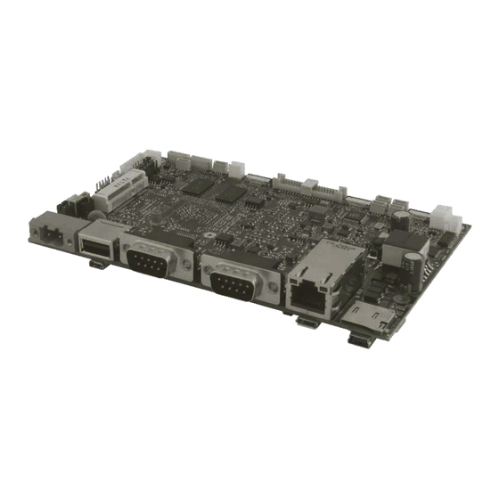
- Page 1 FA30-210 Motherboard 3.5” SBC with Freescale® iMX6 Dual Core Processor User Manual Version 1.1 Document Part Number: 9171111I103L...
-
Page 2: Table Of Contents
Contents PREFACE ..............................- 3 - ABOUT THIS USER MANUAL ........................- 6 - CHAPTER 1: GENERAL INFORMATION ....................- 8 - 1.1 I ............................- 8 - NTRODUCTION 1.2 F ............................. - 8 - EATURES 1.3 P ..........................- 9 - ACKAGE ONTENTS 1.4 M... -
Page 3: Preface
USER MANUAL PREFACE PREFACE Copyright Notice No part of this document may be reproduced, copied, translated, or transmitted in any form or by any means, electronic or mechanical, for any purpose, without the prior written permission of the original manufacturer. Trademark Acknowledgement Brand and product names are trademarks or registered trademarks of their respective owners. - Page 4 USER MANUAL PREFACE Customer Service We provide a service guide as below for any problem by the following steps: First, contact your distributor, sales representative, or our customer service center for technical support if you need additional assistance. You need to prepare the following information before you call: ...
- Page 5 USER MANUAL PREFACE Safety Precautions CAUTION Always ground yourself to remove any static charge before touching the CPU card. Modern electronic devices are very sensitive to static electric charges. As a safety precaution, use a grounding wrist strap at all times. Place all electronic components in a static-dissipative surface or static-shielded bag when they are not in the chassis.
-
Page 6: About This User Manual
FA30-210 Motherboard including layout, mechanical dimensions and product specifications. Chapter 2, Hardware Installation provides information on motherboard components, jumper settings and connector pin assignment of the FA30-210 Motherboard. Chapter 3, Software Programming Guide provides instructions on software installation for all supported operating systems. - Page 7 USER MANUAL CHAPTER 1 GENERAL INFORMATION General Information This chapter includes the FA30-210 Motherboard background information. Sections include: 1.1 Introduction 1.2 Features 1.3 Packing Contents 1.4 Motherboard Specifications 1.5 Functional Description Physical Description - 7 -...
-
Page 8: Chapter 1: General Information
This chapter includes the FA30-210 Motherboard background information. 1.1 Introduction Thank you for choosing the FA30-210 Motherboard. This motherboard is an integrated package that provides a complete RISC platform for project evaluation, application development and solution feasibility testing that decreases lead-time and lowers initial cost and investment. -
Page 9: Package Contents
** The packing contents may vary according to your order. *** If you need to purchase the optional accessories or request part numbers, please contact our sales representatives. 1.4 Motherboard Specifications Model Name FA30-210 Freescale® Cortex™ A9 iMX6 Dual Core System Memory 1GB DDR3 (2GB for Optional) Storage... - Page 10 USER MANUAL CHAPTER 1 GENERAL INFORMATION 1 x CAN Bus (DB9) 1 x RJ-45 10/100/1000 (PoE optional) 1 x Micro SD Card Slot 1 x USB OTG 1 x Mini USB (for debug) 1 x Micro-HDMI Output 1 x LVDS by pin-header 1 x Backlight connector 1 x I2C Touch connector 1 x USB Touch connector...
-
Page 11: Functional Description
USER MANUAL CHAPTER 1 GENERAL INFORMATION 1.5 Functional Description FA30-210 Function Block - 11 -... -
Page 12: Physical Description
USER MANUAL CHAPTER 1 GENERAL INFORMATION 1.6 Physical Description FA30-210 Board Dimensions Unit: mm - 12 -... - Page 13 USER MANUAL CHAPTER 2 HARDWARE INSTALLATION Hardware Installation This chapter introduces the setup procedures of the FA30-210 motherboard, including instructions on how to connect jumpers and peripherals, and mechanical drawings. Sections include: 2.1 Motherboard Components 2.2 Jumpers 2.3 Connectors 2.4 Configuring Serial Port Settings...
-
Page 14: Chapter 2: Hardware Installation
HARDWARE INSTALLATION CHAPTER 2: HARDWARE INSTALLATION This chapter introduces the setup procedures of the FA30-210 platform, including instructions on how to connect jumpers and peripherals, and mechanical drawings. Carefully read the content of this chapter in order to avoid any damages. -
Page 15: Soldier Side
USER MANUAL CHAPTER 2 HARDWARE INSTALLATION Jumpers and switches 2.1.2 Soldier Side - 15 -... -
Page 16: I/O Side
USER MANUAL CHAPTER 2 HARDWARE INSTALLATION 2.1.3 I/O Side 2.2.1 Jumpers This section explains how to set jumpers for correct configuration of the motherboard. A metal-bridge jumper used to close an electric circuit, and it usually consists of two metal pins and one small clip protected by a plastic cover that slides over the pins to connect them. -
Page 17: Jumper List
USER MANUAL CHAPTER 2 HARDWARE INSTALLATION 2.2.1 Jumper List The following table shows the function of each of the board's jumpers. Label Function Note Panel Power Selector 2x3 header, pitch 2.0mm Backlight Power Selector 2x1 header, pitch 2.0mm Panel Control Power Selector 2x1 header, pitch 2.0mm Brightness Adjust Mode 2x1 header, pitch 2.0mm... - Page 18 USER MANUAL CHAPTER 2 HARDWARE INSTALLATION 2.2.1.3 Panel Control Power Selector (JP3) Setting Function 2-3* +3.3V 2.2.1.4 Brightness Adjust Mode Selector (JP4) Setting Function Adjust by VR Knob 2-3* Adjust by Software 2.2.1.5 Backlight Control Mode Selector (JP5) Setting Function 2-3* 2.2.1.6 Boot Mode Selector (SW2) Setting...
-
Page 19: Connectors
USER MANUAL CHAPTER 2 HARDWARE INSTALLATION 2.3 Connectors This section lists all the connectors on the FA30-210 Motherboard and its pin assignments. Motherboard connectors: Front Side Label Connector Note RTC Battery 1 x 2 DF13-2P, pitch 1.25mm Reset White,1 x4 wafer, pitch 1.0mm... -
Page 20: Front Side Setting Description
USER MANUAL CHAPTER 2 HARDWARE INSTALLATION CN45 Microphone 2 x 1 wafer, pitch 2.0mm CN46 Terminal Block 2-pin 2-pin 3.5mm CN47 UART5 White, 1 x8p wafer, pitch 1.0mm CN48 USB 2.0 Type A USB 2.0 Type A I2C Touch 0.5mm Pitch Connectors For LAN1 RJ-45 with POE RT5-1740K22A... - Page 21 USER MANUAL CHAPTER 2 HARDWARE INSTALLATION 2.3.1.3 Backlight Control VR (CN2) Pin № Signal Name PWM/DC control 2.3.1.4 CAN2 (CN3) Pin № Pin № Name Name CAN2_RX CAN2_TX 2.1.3.5 NFC (CN5) Pin No Signal Name Pin No Signal Name +V5S NFC_PWR_C +V3.3S NFC_IRQ...
- Page 22 USER MANUAL CHAPTER 2 HARDWARE INSTALLATION 2.3.1.7 Light Sensor Connector (CN7) Pin № Pin № Signal Name Signal Name LED_B Light _ PWR LED_R LED_G LS_DATA LS_CLK 2.1.3.8 Backlight 1- Vin or 5V (CN8) Pin № Pin № Signal Name Signal Name +BKLPWR +BKLPWR...
- Page 23 USER MANUAL CHAPTER 2 HARDWARE INSTALLATION 2.3.1.11 Right Speaker Out (CN12) Pin No Signal Name ROUT+ ROUT- 2.3.1.12 Left Speaker Out (CN14) Pin No Signal Name LOUT+ LOUT- 2.3.1.13 Mini-PCIe (CN15) Signal Name Signal Name Signal Name Signal Name +3.3V +1.5V +3.3V PCIE_TXM_C...
- Page 24 USER MANUAL CHAPTER 2 HARDWARE INSTALLATION 2.3.1.14 Power output 3.3V (CN17) Blue Pin No Signal Name +3.3V 2.3.1.15 Power output 5V (CN20) Pin No Signal Name 2.3.1.16 Power output 12V (CN23) Yellow Pin No Signal Name +12V 2.3.1.17 DEBUG UART2 Connector (CN33) Signal Name Signal Name Pin No...
- Page 25 USER MANUAL CHAPTER 2 HARDWARE INSTALLATION 2.3.1.18 I2C Touch (CN34 or CN35) Signal Name Signal Name Pin No Pin No Touch_VCC Touch_VCC Touch_INTR Touch_I2C3_SDA Touch_I2C3_SCL Touch_RST 2.3.1.19 LVDS (CN37) Signal Signal Signal Signal Name Name Name Name LCDVDD LVDS0_TX0_N LVDS0_TX2_P LVDSB_TX0- LVDSB_TX2+ LCDVDD...
- Page 26 USER MANUAL CHAPTER 2 HARDWARE INSTALLATION 2.3.1.20 USB Ports (CN38, CN39,CN40, CN41, CN42) USB1 (CN40), USB3(CN41) , USB4 (CN39), USB5 (CN38) USB5 USB4 USB1 CN38(Camera) CN39 CN40 Name Name Name USB_PP5 USB_PP4 USB_PP1 USB_PN5 USB_PN4 USB_PN1 VUSB_VBUS5 VUSB_VBUS4 VUSB_VBUS1 USB3 CN42 CN41 (7”Touch) Name...
-
Page 27: I/O Description
This section contains pin assignment of connectors located on the I/O side of the FA30-210 motherboard. 2.3.2.1 Terminal Block Connector (CN46) FA30-210 motherboard uses 2-pin terminal block connector for DC in power input. Secure the connector to the motherboard with two screws. Minimum Voltage 9V Maximum Voltage 24V Maximum Current 6.6A... - Page 28 Signal Name Signal Name USB_D- USB_D+ 2.3.2.4 Serial Port Connector (CN27) The FA30-210 Motherboard uses COM1: D-Sub 9 serial port connector. The connector secured to the motherboard with two screws. You can configure serial port settings by software. Pin № RS-232...
- Page 29 USER MANUAL CHAPTER 2 HARDWARE INSTALLATION 2.3.2.6 RJ45 with POE (LAN1) The FA30-210 has one 10/100/1000 Mbps LAN interface for connecting to the internet. Support IEEE 802.3at PoE. Pin № MDI0+ PD_A+ MDI0- PD_A+ MDI1+ PD_A- MDI2+ PD_B+ MDI2- PD_B+...
-
Page 30: Configuring Serial Port Settings In Android Os
USER MANUAL CHAPTER 2 HARDWARE INSTALLATION 2.3.2.9 Mini USB Connector for Debug (USB1) FA30-210 motherboard uses Mini USB B type connector for debug purpose only. Pin № Signal Name Pin № Signal Name DBUG_VBU GND(Reserve 2.4 Configuring Serial Port Settings in Android OS Serial COM Port can be configured for RS-232, RS-422 or RS-485. - Page 31 USER MANUAL CHAPTER 2 HARDWARE INSTALLATION 2. Accessibility > System: Comport-Setting. 3. Comport-Setting > Comport 1/ Comport 2/ Comport 3 * Select Comport 1/ Comport 2/ Comport 3 that you want to configure. - 31 -...
- Page 32 USER MANUAL CHAPTER 2 HARDWARE INSTALLATION 4. Comport 1 > RS232/RS422/RS485 * Configure Comport 1 settings - 32 -...
- Page 33 USER MANUAL CHAPTER 3 SOFTWARE PROGRAMMING GUIDE Software Programming Guide This chapter provides information about software programming tools for the FA30-210 platform. Sections include: 3.1 Android Programming Guide 3.2 Linux and Ubuntu Programming Guide - 33 -...
-
Page 34: Chapter 3: Software Programming Guide
3.1 Android Programming Guide All the programming guides can be found in the driver CD that comes in the package with the FA30-210 Motherboard. 3.1.1 ADB Installation Installation link: FA30-210 CD\Android Documents and Files\PC_tool\adb\driver\adb.rar ADB Installation: 1. Unzip “adb.rar” to the desktop. -
Page 35: Gpio
You can find the sample code for Android’s UART installation inside the Driver CD. Sample Code: FA30-210 CD\Android Documents and Files\UART\SampleCode You can find Android’s UART Switch programming guide installation inside the Driver CD that comes with FA30-210 Motherboard. Programming Guide Path: FA30-210 CD\Android Documents and Files\UART\ProgrammingGuide - 35 -... -
Page 36: Ota Update Guide
USER MANUAL CHAPTER 3 SOFTWARE PROGRAMMING GUIDE 3.1.5 OTA Update Guide OTA is a tool which can help you to update OS image. To update Android OS image you need to receive image file. Once you get the image file follow the guideline below. - Page 37 USER MANUAL CHAPTER 3 SOFTWARE PROGRAMMING GUIDE System shows OTA firmware related information. 4. Click Auto-check Update. The system is checking OTA File. It may take some time. - 37 -...
- Page 38 USER MANUAL CHAPTER 3 SOFTWARE PROGRAMMING GUIDE 5. Tap Update Image 6. Make sure the file founded by the system is image update file. Tap OK. - 38 -...
- Page 39 USER MANUAL CHAPTER 3 SOFTWARE PROGRAMMING GUIDE 7. Make sure the battery level is at least 50%. Tap OK. 8. Tap OK. IMPORTANT: Do not disconnect the power source! Do not remove the battery! - 39 -...
- Page 40 USER MANUAL CHAPTER 3 SOFTWARE PROGRAMMING GUIDE 9. After update the system will automatically restart. - 40 -...
-
Page 41: Linux And Ubuntu Programming Guide
You can find all information about Linux’s GPIO installation inside the Driver CD. Programming Guide link: FA30-210 CD\Linux_QT Documents and Files\GPIO\ProgrammingGuide 3.2.2 CAN BUS You can find all information about Linux’s CANBus installation inside the Driver Programming Guide link: FA30-210 CD\Linux_QT Documents and Files\Canbus\ProgrammingGuide 3.2.3 UART Switch... - Page 42 USER MANUAL CHAPTER 4 TECHNICAL SUPPORT Technical Support This chapter contains directory to technical support. - 42 -...
-
Page 43: Chapter 4: Technical Support
USER MANUAL CHAPTER 4 TECHNICAL SUPPORT CHAPTER 4: TECHNICAL SUPPORT This chapter includes the directory for technical support. Free technical support is available from our engineers every business day. We are always ready to give advice on application requirements or specific information on the installation and operation of any of our products.
Need help?
Do you have a question about the FA30-210 and is the answer not in the manual?
Questions and answers