
Related Manuals for Winmate FA30-200


Summary of Contents for Winmate FA30-200
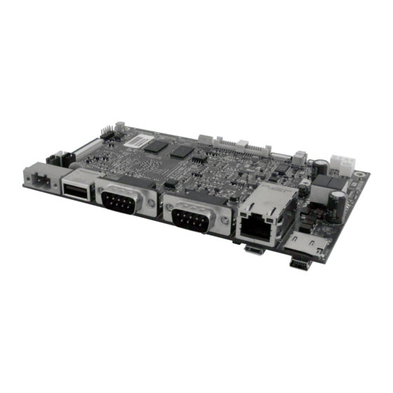
- Page 1 FA30-200 Motherboard 3.5” SBC with Freescale® iMX6 Dual Core Processor V100 User Manual Version 1.0...
-
Page 2: Preface
(e. g., with A for October, B for November and C for December). For example, the serial number 1W16Axxxxxxxx means October of year 2016. FA30-200 MOTHERBOARD... - Page 3 In addition, free technical support is available from our engineers every business day. We are always ready to give advice on application requirements or specific information on the installation and operation of any of our products. Please do not hesitate to call or e-mail us. FA30-200 MOTHERBOARD...
- Page 4 An important note indicates information that is important for you to know. CAUTION A Caution alert indicates potential damage to hardware and explains how to avoid the potential problem. WARNING! An Electrical Shock Warning indicates the potential harm from electrical hazards and how to avoid the potential problem. FA30-200 MOTHERBOARD...
-
Page 5: Safety Precautions
C. The equipment has been exposed to moisture. D. The equipment does not work well, or you cannot get it to work according to the user’s manual. E. The equipment has been dropped and damaged. F. The equipment has obvious signs of breakage. FA30-200 MOTHERBOARD... -
Page 6: About This User Manual
ABOUT THIS USER MANUAL This User Manual provides information about the FA30-200 Motherboard. Some pictures in this guide are samples and can differ from actual product. NOTE Chapter Descriptions Chapter 1, General Information provides general information about the FA30-200 Motherboard including layout, mechanical dimensions and product specifications. -
Page 7: Table Of Contents
CONTENTS PREFACE ................................I ABOUT THIS USER MANUAL ........................... VI CHAPTER 1: GENERAL INFORMATION ......................1 1.1 I ..............................1 NTRODUCTION 1.2 F ................................ 1 EATURES 1.3 P ............................2 ACKING ONTENTS 1.4 M .......................... 3 OTHERBOARD PECIFICATIONS 1.5 F .......................... - Page 8 3.1.4 UART Sample Code ..........................22 3.1.5 OTA Update Guide ..........................23 3.2 L ......................26 INUX AND BUNTU ROGRAMMING UIDE 3.2.1 GPIO ..............................26 3.2.2 CAN BUS ............................. 26 3.2.3 UART Switch ............................26 CHAPTER 4: TECHNICAL SUPPORT ........................28 FA30-200 MOTHERBOARD...
- Page 9 USER MANUAL CHAPTER 1 GENERAL INFORMATION General Information This chapter includes the FA30-200 Motherboard background information. Sections include: 1.1 Introduction 1.2 Features 1.3 Packing Contents 1.4 Motherboard Specifications 1.5 Functional Description Physical Description FA30-200 MOTHERBOARD...
-
Page 10: Chapter 1: General Information
FA30-200 Motherboard empowered by a Freescale® Cortex™ – A9 iMX6 Dual Core 1 GHz processor. In peripheral connectivity, FA30-200 SBC features serial port connector, CAN BUS connector, USB 2.0 A-type connector, LAN port with PoE function support, Micro HDMI, Debug port, and one Micro SD card slot. -
Page 11: Packing Contents
* Pictures are for reference only and can differ from actual product. ** The packing contents may vary according to your order. *** If you need to purchase the optional accessories or request part numbers, please contact our sales representatives. FA30-200 MOTHERBOARD... -
Page 12: Motherboard Specifications
146 mm x 91.6 mm (3.5" Form Factor) Characteristics (W x H x D) Operating Temperature -20 deg. C to +60 deg. C Environment Storage Temperature -40 deg. C to +70 deg. C Operating Humidity 10% to 95% (non-condensing, RH) FA30-200 MOTHERBOARD... -
Page 13: Functional Description
USER MANUAL CHAPTER 1 GENERAL INFORMATION 1.5 Functional Description FA30-200 Function Block (V200) FA30-200 MOTHERBOARD... -
Page 14: Physical Description
USER MANUAL CHAPTER 1 GENERAL INFORMATION 1.6 Physical Description FA30-200 Board Dimensions (V200) Unit: mm FA30-200 MOTHERBOARD... -
Page 15: Hardware Installation
Hardware Installation This chapter introduces the setup procedures of the FA30-200 motherboard, including instructions on how to connect jumpers and peripherals, and mechanical drawings. Sections include: 2.1 Motherboard Components 2.2 Jumpers 2.3 Connectors 2.4 Configuring Serial Port Settings FA30-200 MOTHERBOARD... -
Page 16: Chapter 2: Hardware Installation
Carefully read the content of this chapter in order to avoid any damages. 2.1 Motherboard Components This section explains the location of the components on the FA30-200 motherboard. 2.1.1 Component Side FA30-200 MOTHERBOARD... -
Page 17: Soldier Side
USER MANUAL CHAPTER 2 HARDWARE INSTALLATION 2.1.2 Soldier Side 2.1.3 I/O Side FA30-200 MOTHERBOARD... -
Page 18: Jumpers
The jumper setting diagram is shown below. When the jumper cap is placed on both pins, the jumper is SHORT. The illustration below shows a 3-pin jumper; pins 1 and 2 are short. If you remove the jumper cap, the jumper is OPEN. PIN 1-2 SHORT FA30-200 MOTHERBOARD... -
Page 19: Jumper List
PIN2 Boot from fuses (default) 1 Serial downloader Boot from board settings Reserved 2.3 Connectors This section lists all the connectors on the FA30-200 Motherboard and its pin assignments. Motherboard connectors: Front Side Label Connector Note RTC Battery 1 x 2 DF13-2P, pitch 2.0mm Light Sensor Connector 0.5mm Pitch Connectors For FFC... -
Page 20: Front Side Setting Description
CN30 Micro SD Micro SD 2.3.1 Front Side Setting Description This section includes pin assignment of connectors located on the front side of the FA30-200 Motherboard. 2.3.1.1 BT1: RTC Battery Pin № Signal Name +3.3V 2.3.1.2 CN7: Light Sensor Connector Pin №... -
Page 21: Cn12: R- Speaker Out
ROUT- 2.3.1.5 CN14: L- Speaker Out Pin No Signal Name LOUT+ LOUT- 2.3.1.6 CN17: 3.3V output Pin No Signal Name +3.3V 2.3.1.7 CN20: 5V output Pin No Signal Name 2.3.1.8 CN23: 12V output Pin No Signal Name +12V FA30-200 MOTHERBOARD... -
Page 22: Cn41: Touch
DISP0_DAT17 DISP0_DAT18 DISP0_DAT19 DISP0_DAT20 DISP0_DAT21 DISP0_DAT22 DISP0_DAT23 DISP0_HSYNCH DISP0_VSYNCH DISP0_CLK no function no function N53696863 N53696863 no function LCD_SHUT_L no function no function no function no function no function DISP0_DRDY 2.3.1.11 CN45: Mic Connector Pin No Signal Name FA30-200 MOTHERBOARD... -
Page 23: J5: I2C Touch Connector
2.3.1.13 PANEL: LVDS Connector Pin № Signal Name Pin № Signal Name Pin № Signal Name LCDVDD LVDS0_TX0_N LCDVDD LVDS0_TX0_P LCDVDD LVDS0_TX1_N LVDS0_TX1_P LVDS0_TX2_N LVDS0_TX2_P LVDS0_CLK_N LVDS0_CLK_P LVDS0_TX3_N LVDS0_TX3_P LVDS1_TX0_N LVDS1_TX0_P LVDS1_TX1_N LVDS1_TX1_P LVDS1_TX2_N LVDS1_TX2_P LVDS1_CLK_N LVDS1_CLK_P LVDS1_TX3_N LVDS1_TX3_P FA30-200 MOTHERBOARD... -
Page 24: I/O Description
CHAPTER 2 HARDWARE INSTALLATION 2.3.2 I/O Description This section contains pin assignment of connectors located on the I/O side of the FA30-200 motherboard. 2.3.2.1 DC IN: Terminal Block Connector FA30-200 motherboard uses 2-pin terminal block connector for DC in power input. Secure the connector to the motherboard with two screws. -
Page 25: Cn28: Can Bus Connector
2.3.2.5 LAN1: RJ45 with POE Pin № MDI0+ PD_A+ MDI0- PD_A+ MDI1+ PD_A- MDI2+ PD_B+ MDI2- PD_B+ MDI1- PD_A- MDI3+ PD_B- MDI3- PD_B- 2.3.2.6 CN30: Micro SD Pin № Signal Name Pin № Signal Name DATA2 DATA3 +3.3V DATA0 DATA1 Card_Det FA30-200 MOTHERBOARD... -
Page 26: Cn32: Usb Otg Host
Pin № Signal Name Pin № Signal Name USB_OTG_D- USB_OTG_D+ USB_OTG_ID 2.3.2.8 USB1: Mini USB Connector (Debug) FA30-200 motherboard uses Mini USB connector for debug purpose only. Pin № Signal Name Pin № Signal Name TXD233 RXD232 DBUG-VBUS FA30-200 MOTHERBOARD... -
Page 27: Configuring Serial Port Settings In Android Os
HARDWARE INSTALLATION 2.4 Configuring Serial Port Settings in Android OS User can configure serial COM Port for RS-232, RS-422 or RS-485 by software. Winmate provides application for configuring COM port settings for Android OS. Configuring COM Port settings in Android OS: Step 1 Settings >... - Page 28 HARDWARE INSTALLATION Step 3 Comport-Setting > Comport 1/ Comport 2/ Comport 3 * Select Comport 1/ Comport 2/ Comport 3 that you want to configure. Step 4 Comport 1 > RS232/ RS422/ RS485 * Configure Comport 1 settings FA30-200 MOTHERBOARD...
- Page 29 USER MANUAL CHAPTER 3 SOFTWARE PROGRAMMING GUIDE Software Programming Guide This chapter provides information about software programming tools for the FA30-200 platform. Sections include: 3.1 Android Programming Guide 3.2 Linux and Ubuntu Programming Guide FA30-200 MOTHERBOARD...
-
Page 30: Chapter 3: Software Programming Guide
3.1 Android Programming Guide All the programming guides can be found in the driver CD that comes in the package with the FA30-200 Motherboard. 3.1.1 ADB Installation Installation link: FA30-200 CD\Android Documents and Files\PC_tool\adb\driver\adb.rar ADB Installation: 1. Unzip “adb.rar” to the desktop. -
Page 31: Gpio
You can find all information about Android’s CAN BUS installation inside the Driver Programming Guide link: FA30-200 CD\Android Documents and Files\Canbus\API\doc\ FA30-200 3.1.4 UART Sample Code You can find the sample code for Android’s UART installation inside the Driver CD. -
Page 32: Ota Update Guide
Step 2 Insert the micro SD card to the slot in the device. In the APPs menu tap OTA Image Upd Step 3 The system is checking OTA File. It may take some time. Step 4 Tap Update Image FA30-200 MOTHERBOARD... - Page 33 CHAPTER 3 SOFTWARE PROGRAMMING GUIDE Step 5 Make sure the file founded by the system is image update file. Tap OK. Step 6 Tap OK. Make sure the battery level is at least 50%. Step 7 Tap OK. FA30-200 MOTHERBOARD...
- Page 34 USER MANUAL CHAPTER 3 SOFTWARE PROGRAMMING GUIDE IMPORTANT: Do not disconnect the power source! Do not remove the battery! Step 8 After update the system will automatically restart. FA30-200 MOTHERBOARD...
-
Page 35: Linux And Ubuntu Programming Guide
GPIO pins have no predefined purpose, and go unused by default. You can find all information about Linux’s GPIO installation inside the Driver CD. Programming Guide link: FA30-200 CD\Linux_QT Documents and Files\GPIO\ProgrammingGuide 3.2.2 CAN BUS You can find all information about Linux’s CANBus installation inside the Driver CD. -
Page 36: Technical Support
USER MANUAL CHAPTER 4 TECHNICAL SUPPORT Technical Support This chapter contains directory to technical support. FA30-200 MOTHERBOARD... -
Page 37: Chapter 4: Technical Support
If any problem occurs fill in problem report form enclosed and immediately contact us. To find Drivers and SDK, please refer to the Driver CD that comes in the package or contact us. For a detailed Android 4.4 user guide, follow the download path below: http://static.googleusercontent.com/media/www.google.com/en/us/help/hc/images/androi d/android_ug_42/Android-Quick-Start-Guide.pdf FA30-200 MOTHERBOARD...
Need help?
Do you have a question about the FA30-200 and is the answer not in the manual?
Questions and answers