Table of Contents
Advertisement
4200 Checkweigher
W I T H B A R G R A P H
&
4100L Checkweigher
Digital Electronic Indicators
INSTRUCTION MANUAL
DORAN SCALES, INC.
1315 PARAMOUNT PKWY
BATAVIA, IL. 60510
1-800-262-6844
FAX: 630/879-0073
http://www.doranscales.com
PN : MAN0003
MANUAL REVISION : 4.3
SOFTWARE REVISION : 4.6
MAN03R43 12/98 TW
Advertisement
Table of Contents

Subscribe to Our Youtube Channel
Related Manuals for Doran 4200


Summary of Contents for Doran 4200
- Page 1 4200 Checkweigher W I T H B A R G R A P H & 4100L Checkweigher Digital Electronic Indicators INSTRUCTION MANUAL DORAN SCALES, INC. 1315 PARAMOUNT PKWY BATAVIA, IL. 60510 1-800-262-6844 FAX: 630/879-0073 http://www.doranscales.com PN : MAN0003 MANUAL REVISION : 4.3 SOFTWARE REVISION : 4.6...
-
Page 3: Table Of Contents
Figure 1 Model 4200 Enclosure Types ............ Unpacking ....................Installation ....................Electrical Connections ................Section 2. Quick Setup Guide ................Figure 2. 4200 Main Board Connections and Switches ......Entering the Setup Mode ................Selecting a Capacity and Resolution ............Analog Calibration ..................Digital Calibration .................. - Page 4 Section 5. Checkweighing ................Net and Zero Checkweighing ..............Tolerance Entry and Display Modes ............4200 Standard (S42, P42, d42) ............Value Per Bar (Sd, Pd, dd) ..............Scaled (SS, PS, dS) ................Modified Value Per Bar (SdA, PdA, ddA) ..........
- Page 5 Table of Contents 3. Motion Aperture ................4. Serial Data Output ................. 5. Start Up Units ................5a. Startup Gross/Net ............... 6. Scale Capacity ................7. Startup Zero .................. 8. Operating Mode ................9. Push-button Enable ............... 9a. Beeper Enable ................10.
- Page 6 Table of Contents DIP Switch Settings ................Digital Calibration - MOST USED CALIBRATION ......... Exiting the Calibration Mode ..............Zero and Span Switch Settings for Old Revision Boards ......Section 8. Serial Communications ..............Port 1 - Duplex ..................Port 1 (Duplex) Command Summary ............General Scale Commands ..............
- Page 7 Table of Contents Checkweighing ..................Parameter Setup ..................Calibration ....................Section 10. Error Codes ..................Section 11. Troubleshooting ................Configuration and Product Printout ............Resetting Parameters ................Resetting Scale ..................Returning Scale for Service ..............Section 12. Connections ................... Port 1 (Duplex) Hardware Configuration ..........Port 2 (Printer) Hardware Configuration ...........
- Page 8 Please be sure to read this entire manual to assure yourself of getting all the benefits of these and other advanced features of the Doran Scales Model 4200. This scale is backed by a full 2 year factory warranty. Please contact Sales Department for sales for ordering...
-
Page 9: Section 1. Unpacking And Installation
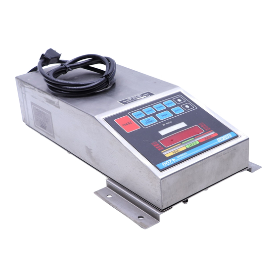
The 3 enclosures are pictured below. In addition to the 4200 models, this manual covers the Model 4100L, which is a "Legal for Trade" version of the Model 4100 Checkweigher. The 4100L is identical to the 4200 electronically, but is different in the display and front panel. -
Page 10: Unpacking
INSTALLATION 4200 Tower: Models with 10" x 10", 12" x 12", and 12" x 16" platforms are shipped in one piece (fully assembled). When unpacking models with 18" x 18", 18" x 24", and 24"... -
Page 11: Electrical Connections
Section 6 of this manual. ELECTRICAL CONNECTIONS The Model 4200 requires 120 VAC, 50/60 Hz power (240 VAC or DC power optional). Be sure the AC power is not excessively noisy - this can occur if large inductive loads, such as solenoids or motors, are on the same power line. -
Page 12: Section 2. Quick Setup Guide
In most cases, your Model 4200 will be completely configured and calibrated at the factory. If the indicator is ordered without a Doran platform, the indicator will need to be set up using the following guide. If you have any questions about setting up or calibrating the indicator, refer to the more complete sections in this manual for more information. -
Page 13: Entering The Setup Mode
S2 - position 9 or S1 to the Setup Mode. Model 4200 Tower: Remove the small rectangular access panel on the rear of the tower by removing the two hex screws holding it in place. Flip S1 located on... -
Page 14: Digital Calibration
Proceed to DIGITAL CALIBRATION. DIGITAL CALIBRATION The Model 4200 must be calibrated with a test weight equal to at least 20% of the scale capacity (5% for capacities over 1000 lb). The greater the test weight, the better the calibration will be throughout the entire active range of the platform or load cell assembly (calibrating at capacity is ideal). - Page 15 Section 2 Quick Setup Guide Place the test weight on the platform. Adjust the displayed weight to match the test weight using the UP or DOWN arrows. When the displayed weight is correct, press the UNITS button to save the calibration - the display will show "Ent SP"...
-
Page 16: Section 3. Display And Keyboard
Section 3. Display and Keyboard The front panel of the 4200 contains the digital weight display, the checkweigh bargraph display, the status annunciators, and the push-buttons necessary for controlling the various functions of the indicator. In addition, the capacity label is displayed through a window on the front panel. -
Page 17: Gross/Net Push-Button
(parameters and options). UNIT ANNUNCIATORS The Model 4200 supports the display of lb, kg, oz, g and lb-oz. When the indicator is in the lb, kg, or oz display modes, their respective annunciators will be enabled. When the indicator is in the lb-oz display mode, both the "lb"... -
Page 18: Status Annunciators
Section 3 Display and Keyboard STATUS ANNUNCIATORS The Model 4200 provides 5 additional status annunciators during normal weighing operations. "MOT" Indicates that the indicator is in the motion state. This means that there is movement on the platform. The movement must settle before a stable state is achieved and is indicated when the "MOT"... -
Page 19: Section 4. Scale Operation
4200's power by using its other features as you require. POWER UP To turn on the 4200, simply plug it into a proper wall receptacle. The power plug is the main power disconnect, the only way to remove power from the scale is to pull the power plug. -
Page 20: Products
Section 4 Scale Operation PRODUCTS The 4200 has the ability to store information for 20 products (200 products if option 42 OPT 27 is installed). There is a separate tare, over, and under value associated with each product. These values are saved in nonvolatile memory so that they are not lost if power is removed. -
Page 21: Tare Operation
If an attempt is made to enter a negative gross weight as a tare, the 4200 will display an error message "tar -" to warn you that it cannot be entered. -
Page 22: Dis Mode
- press repeatedly for slow update. When the correct value is displayed, press OVER or UNDER again to store it as the new tolerance value. The 4200 will display "Ent Pr" to indicate that the new value has been accepted. If you don't get... -
Page 23: Ptt Entry Mode
PRINT button is pressed, a data transmission is initiated. The weight data is transmitted only when the scale is not in motion and not in overrange. Refer to Section 8 for details on the 4200 Data Interface. -
Page 24: Gross/Net
42 OPT 05 is usually also needed. The 4200 can be set up to allow entry of these values using the UP and DOWN arrow buttons, or actual platform weight. In addition, setpoint entry can be disabled in order to prevent tampering or accidental erasure. -
Page 25: Set Entry Mode
Section 4 Scale Operation When the correct setpoint is displayed, press the PROD button once more and the display will show the current value entered for the setpoint selected. If the value is just being recalled, pressing the PROD button again will return the scale to normal weighing with no change to the setpoint value. -
Page 26: Sta Mode
Section 4 Scale Operation STA MODE In this mode, the seven setpoints indicate the status of various functions of the 4200, e.g. motion, overload, etc. There are therefore no values to change. Listed below are the functions of each setpoint in this mode. In this mode, normal setpoints cannot be used--all setpoints are used to indicate the scale status. -
Page 27: Time And Date
Section 4 Scale Operation After the buffers are set up as explained in Section 8, the print format parameter must be set to option 13 (see Section 6, parameter 15). When the buffers are set up and print format 13 selected, the buffers can be used to print as required. -
Page 28: Section 5. Checkweighing
The OVER, UNDER and ACCEPT indicators can be used with or without the digital weight display. Either can be turned off for maximum flexibility of the 4200 scale display. See "Checkweigh Operation (C.O.)" and "Display Operation (doP)" setup parameters. -
Page 29: Tolerance Entry And Display Modes
'd' are DIS modes. Each of these modes is explained fully in Section 4. The 4 display modes are: 4200 Standard (S42, P42, and d42), Value Per Bar (Sd, Pd, and dd), Scaled (SS, PS, and dS), and Modified Value Per Bar (SdA, PdA, and ddA). -
Page 30: 4200 Standard (S42, P42, D42)
Section 5 Checkweighing 4200 Standard (S42, P42, d42) In this mode, the whole Over, Under, or Accept display region will illuminate for the given condition. For example, if Over is set for 2.50 lb, and 2.51 lb is placed on the platform, the whole Over region will light up. -
Page 31: Value Per Bar (Sd, Pd, Dd)
Section 5 Checkweighing Value per Bar (Sd, Pd, dd) This mode is used for zero checkweighing only. The Over and Under values determine the value of each bargraph bar for that part of the display. The Over value specifies the value for each bar to the right of the center of the Accept region. -
Page 32: Scaled (Ss, Ps, Ds)
Section 5 Checkweighing Scaled (SS, PS, dS) This mode is used strictly in net checkweighing and is similar to the 4200 standard mode. The difference is in the fact that single bars can illuminate, giving an indication of where the weight on the scale is in relation to the capacity of the scale. -
Page 33: Modified Value Per Bar (Sda, Pda, Dda)
Section 5 Checkweighing Modified Value per Bar (SdA, PdA, ddA) This mode can be used for zero or net checkweighing and is similar to the Value per Bar mode. The difference is that the values per bar are calculated instead of specified. The Over value determines the over point, the Under value determines the under point, and the value per bar is found by dividing the difference between the Over and Under values by 10. -
Page 34: Section 6. Parameter Setup
The 4200 has a powerful software "User Setup Menu" that allows you to program up to 25 scale parameters such as update rate, weight display units, scale capacity and resolution, and much more. This allows you to customize the 4200 to your exact needs - and it is easy! It is a good idea to familiarize yourself with the "User Setup Menu"... -
Page 35: Entering The Setup Mode
Section 6 Parameter Setup ENTERING THE SETUP MODE 4200 Tower: Remove the small rectangular access panel on the rear of the scale indicator by removing the two hex screws holding the panel in place. Flip the red handled toggle switch (S1) located on the main board just inside the access port. -
Page 36: Setup Parameters
SETUP PARAMETERS The following is a detailed list of the parameters and options in the 4200, as well as a description of how they affect the operation of the scale. Be sure to read these descriptions carefully, and select settings that you feel will best fit your needs. -
Page 37: 1A. Analog Filter
Section 6 Parameter Setup The "A1" and "A2" settings refer to a software utility called "Auto Averaging". In these modes, averaging will be disabled when the scale is in motion in order to achieve a fast update. When the scale stabilizes, averaging is reenabled to achieve the most stable final reading. -
Page 38: Motion Aperture
Startup in "g" (uses kg annunciator) The Startup Unit is simply the weight display unit that the 4200 reads in when the scale is turned on. Select the unit you will use exclusively or the unit most frequently used as your... -
Page 39: 5A. Startup Gross/Net
NTEP or CWM as a legal for trade display. If the "lb & oz" option is selected for SU and the operating mode is set for "Legal for Trade", the 4200 will start up in the "lb" weight display mode. In addition, if a capacity of 500 lb or above (see below) is selected, the "lb &... - Page 40 Section 6 Parameter Setup 15 x .005 lb / 6.8 x .002 kg / 240 x .1 oz 15 x .002 lb / 6.8 x .001 kg / 240 x .05 oz 10 x .001 lb / 4.5 x .0005 kg / 160 x .02 oz 30 x .01 lb / 13.6 x .005 kg / 480 x .2 oz 30 x .005 lb / 13.6 x .002 kg / 480 x .1 oz 20 x .002 lb / 9.1 x .001 kg / 320 x .05 oz...
-
Page 41: Startup Zero
Refer to Section 7 on Calibrating the 4200 to make sure that the scale is properly calibrated after changing capacity. -
Page 42: Operating Mode
HB44 (Legal for Trade) +/- 1.9% gross zero range. Canadian Weights and Measures Approval (Legal for Trade) +/- 4.0 % gross zero range. The Operating Mode defines whether or not the 4200 will operate in a "Legal for Trade" or a "Not Legal for Trade" mode. -
Page 43: Push-Button Enable
1:3000 displayed resolution 1:6000 displayed resolution The 4200 is provided with the ability to increase its displayed resolution from a nominal 1 part in 3000 to 1 part in 6000. This ability is provided for users who require finer resolution weighing for more precise checkweighing. -
Page 44: Tolerance (Over/Under) Entry Mode
Over and Under values. Modified value per bar, disable entry. NOTE: When 4200 emulation is selected, the Over and Under areas on the bargraph indicator will all be turned on when the scale senses either Over or Under weights. -
Page 45: Tare Entry Mode
The Tare Entry Mode parameter allows the user to select how the tare parameter in the 4200 operates. It can be either a standard "Push to Tare" button, causing the weight display to come to zero when pressed, or it can be used in conjunction with the UP and DOWN arrow buttons to preset a tare value from the front panel. -
Page 46: Data Bits And Parity, Port 1 - Printer
Section 6 Parameter Setup 14. Data Bits and Parity, Port 2 - Printer (d.b.P) Option Description 8 data bits, no parity. 7 data bits, no parity. 7 data bits, odd parity. 7 data bits, even parity. The Data Bits and Parity parameter is used to select the number of data bits for each character transmitted through the simplex (printer) port. -
Page 47: Checkweigh Operation
Section 6 Parameter Setup The Print Format parameter allows the 4200 to print a variety of formats for different applications and printer requirements. Select the format that best fits your data and printer requirements. 16. Checkweigh Operation (C.O.) Option Description Net only, all time. -
Page 48: Convert Operation Select
Section 6 Parameter Setup 17. Convert Operation Select (CSL) Option Description 4-way convert, lb-kg(g)-oz-lb&oz. 3-way convert, lb-kg(g)-oz. 2-way convert, lb-kg(g). 2-way convert, lb-lb&oz. 2-way convert, kg(g)-oz. The Convert Select parameter is used to select how the UNITS push-button operates when enabled. -
Page 49: Unit Time On
Section 6 Parameter Setup 20. Unit Time On (tdy) Option Description Constant on. If battery option is installed, press and hold ZERO to turn off. Time delay, unit on for 0.5 minute. Time delay, unit on for 1.0 minute. Time delay, unit on for 1.5 minutes. Time delay, unit on for 2.0 minutes. -
Page 50: Scale Id
The Setpoint Entry Mode parameter allows the user to select how the setpoint values are entered in the 4200. Setpoint values can be entered digitally by using the UP or DOWN arrows to enter the value or by placing the actual weight on the platform that corresponds to the desired setpoint value. -
Page 51: Setpoint Output Operation
Section 6 Parameter Setup 23. Setpoint Output Operation (S.P.O) Option Description Setpoint output disabled, active high all the time. Active high, no latch, all weights. Active high, no latch, stable weights. Active high, latched, all weights. Active high, latched, stable weights. Active high, pulsed for 1/16 second, all weights. -
Page 52: Time And Date Output Operation
Section 6 Parameter Setup The pulse option can be selected to output a pulse for 1/16th of a second once the setpoint is set. If the active high selection is made with the pulse selection, the output will go from .6vdc to 5vdc for about 1/16th of a second, then return to .6vdc. -
Page 53: Line Feed And Form Feed
Section 6 Parameter Setup 25. Line Feed and Form Feed (PtF) Option Description Print no line or form feed. Print 1 line feed only. Print 2 line feeds only. Print 3 line feeds only. Print 4 line feeds only. Print 5 line feeds only. Print 6 line feeds only. -
Page 54: Section 7. Calibration
Section 7. Calibration The 4200 was designed to make calibration as simple and flexible as possible. All that is needed to calibrate the 4200 is one test weight and some simple manipulation of the front panel push-buttons. Refer to Figure 5 below for push-button functions in the calibrate mode. -
Page 55: Reading Raw A/D Platform Data
The analog zero calibration is necessary because a dead load is always present on the load cell due to the weight of the platter and any other weighing apparatus. This dead load is compensated for electronically within the 4200, and switch settings are provided for adjustment. -
Page 56: Dip Switch Settings
Section 7 Calibration Zero Offset Selection (for mv/v, divide by 10) pos 5 pos 4 pos 3 pos 2 pos 1 35 mv Zero Down 30 mv Zero Down 25 mv Zero Down 20 mv Zero Down 15 mv Zero Down 10 mv Zero Down 5 mv Zero Down 0 mv Zero Down/Up... -
Page 57: Dip Switch Settings
Section 7 Calibration Span Range Selection (Active Live Load) pos 8 pos 7 pos 6 0.50 - 1.25 mv/v 1.00 - 2.50 mv/v 2.00 - 3.50 mv/v DIGITAL CALIBRATION The digital calibration is necessary to match the raw span value to the actual displayed weight. -
Page 58: Exiting The Calibration Mode
"C", indicating that the 4200 is now ready for span calibration. With the 4200 displaying 0 and still flashing "C" in the leftmost digit, place the known test weight on the scale platform. The display will show the weight of the test load. Use the UP and DOWN arrows to adjust the displayed weight to match the actual weight on the platter. - Page 59 Section 7 Calibration Span switch settings - PCB035 Rev. 2.0 (no zero pot) Load Cell Output S3-1 S3-2 S3-3 S3-4 0.5 mv/v 0.75 mv/v 1.0 mv/v 1.5 mv/v 2.0 mv/v 2.5 mv/v Zero Offset switch settings - PCB035 Rev. 2.0 (with zero pot) Zero Offset S2-1 S2-2...
-
Page 60: Section 8. Serial Communications
The 4200 command set allows the operator to perform any of the front panel push-button functions, and some others that are not accessible from the front panel. -
Page 61: Port 1 (Duplex) Command Summary
4200. The 4200 also has an option setting to enable or disable handshaking (see Section 6, parameter 19). If handshaking is on, the scale will return an asterisk upon recognition of a valid command and completion of the specified task. - Page 62 CTRL+V (^V) is sent without an address to disable the pass-through function. For example, to send "DORAN" to the printer port, first type "00^P", followed by a carriage return, then "DORAN", and finally "^V", followed by a carriage return. The baud rates and parity settings must be the same for both ports to make use of this feature.
-
Page 63: Data Request Commands
Section 8 Serial Communications Selects the label number. This accomplishes the same thing as pressing the PROD button on the front panel and using the UP and DOWN arrows to select the label. Follow the command with the two digit label number -- see examples below. Refer to the LABEL BUFFER heading later in this section for more information. - Page 64 Section 8 Serial Communications Requests the current product number. Do not send any numbers after the command. Requests all the product values (00-99). Do not send any numbers after the command. Requests the scale status string. Do not send any numbers after the command. The scale status string is 6 characters long.
-
Page 65: Data Clear Commands
Section 8 Serial Communications Data Clear Commands Data Clear commands are two-character commands that clear specified registers (overs, unders, tares, etc.). All commands except CM must be followed by a two digit number that specifies which register to clear. Remember to precede each command with the address of the scale, and follow each command with a carriage return. -
Page 66: Consecutive Counter Commands
Section 8 Serial Communications Displays a momentary message on the front panel. Follow the command with the message, which may be up to 6 characters. The characters must be displayable by a 7-segment display. Enters the specified format string into the specified label buffer. Refer to LABEL BUFFER FORMAT later in this section for more information. -
Page 67: Print Buffer
See Section 4 for selecting the "LBL XX" prompt to select the buffer format to use. The protocol uses a series of control codes within the format to instruct what the 4200 is to print at that time in the format. The format can also contain literal characters that can print... -
Page 68: Formatting The Label Buffer
Formatting the Label Buffer To format the buffer, the number of buffers that are to be set up must be sent to the 4200 first. For example, the string "00EB02" will instruct the 4200 to set up 2 buffers for formatting and will allocate 120 characters to each buffer. - Page 69 Section 8 Serial Communications Sends a carriage return (ASCII 13). (lower case 'L') Sends a line feed (ASCII 10). Sends a form feed (ASCII 12). Prints the gross weight with decimal point. Prints the gross weight without decimal point. Prints the net weight with decimal point. Prints the net weight without decimal point.
-
Page 70: Port 2 - Simplex
Prodigy printer). A limitation of this feature is that if a string is sent to the 4200 and it recognizes it as a valid command, it will act on it, so only strings that are non-valid commands should be sent. -
Page 71: Data Transmission (Print) Modes
Section 8 Serial Communications Data Transmission Modes Transmission from the 4200 can be initiated in one of 9 ways as follows: TRANSMIT ON DEMAND (TOD) When the data output mode is set to Transmit on Demand (tod), transmission of weight data from the printer port is initiated by pressing the PRINT button. -
Page 72: Autoprint 3 (Ap3)
Section 8 Serial Communications and remain disabled until the scale returns to "Startup Gross Zero" (object is removed). Once the scale returns to "Startup Gross Zero", the data output is re-enabled to transmit the next stable, nonzero weight. This differs from the Auto-Print 1 mode in that in "AP1" mode, the scale did not have to return to zero to re-enable the data output;... -
Page 73: Print Formats
Section 8 Serial Communications Print Formats PRT FORMAT LB, KG, OZ, or G LB - OZ 100.55 lb (G/N) (O/A/U) 100 lb 8.8 oz (G/N) (O/A/U) SCALE I.D.: 01 SCALE I.D.: 01 100.55 lb (G/N) (O/A/U) 100 lb 8.8 oz (G/N) (O/A/U) SCALE I.D.: 01 SCALE I.D.: 01 PRODUCT NO.: 12... -
Page 74: Configuration And Product Printout
CONFIGURATION AND PRODUCT PRINTOUT The 4200 has the ability to print out the configuration of the unit. If the PRINT push-button is held while the unit is plugged in or the ZERO push-button is pressed (on battery units only), the scale will print a list of parameters and the options selected for those parameters. -
Page 75: Section 9. Model 4100L
The Model 4100L is a Handbook 44 (NTEP) certified version of the Model 4100 Checkweigher. The scale has limited options but is as versatile as the Model 4200. The electronics used in the Model 4100L are the same as the electronics used in the Model 4200. -
Page 76: Display And Push-Buttons
The 4100L uses the same display as the 4100, but the main board electronics are the same as the 4200. There is a single zero push-button on top of the scale, and optional convert, print, tare or gross/net push-buttons are available. - Page 77 Section 9 Model 4100L Parameter Option Averaging (AVg) Analog Filter Zero Tracking (AZt) Motion Aperture (MA) Serial Output (d.o.) T.O.D. Startup Unit (S.U.) Scale Capacity (CAP) Variable Startup Zero (S.U.O) Operating Mode (oP) Push Button Enable (P.b.) Beep On Displayed Resolution (CtS) 3 Tolerance Entry (toL) Tare Entry (tAr) Simplex Baud Rate (b.r.t)
-
Page 78: Calibration
Section 9 Model 4100L Parameter 17 should always be set to 3 way or 2 way convert since the lb-oz mode is not an recognized unit within Handbook 44. Any deviation from the suggested settings may void the approval capabilities of the scale. -
Page 79: Section 10. Error Codes
Section 10. Error Codes Error Code: "Er nSt" Scale not stable Cause: Vibration/air currents affecting platform or possible trouble with load cell or main board. Remedy: Isolate platform from the source of vibration and/or air currents or replace defective load cell or main board. Error Code: "Er C0.u"... - Page 80 Section 10 Error Codes Error Code: "Er EEP" EEPROM fault Cause: The EEPROM is defective or the stored data is corrupted. Remedy: Switch S1 up. "Ldg new" will display. Switch S1 to its original position. This will load defaulted settings to the EEPROM. The scale should return to normal weight display.
- Page 81 Section 10 Error Codes Error code: "Er SP.o" Selected span calibration value (displayed weight) is over full scale capacity. Cause: Improper setting of calibration span value or test load too heavy. Remedy: Recheck test weight value and reset span. Error Code: "Er SP.u"...
- Page 82 Section 10 Error Codes Error Code: "Er Fun" Function Error Cause: This is a normal message that displays when the parameters are being defaulted by the user - see Section 11. Error Code: "Er t-" Negative Tare Error (SET mode) Cause: Attempting to enter a negative tare in the SET mode.
- Page 83 Section 10 Error Codes Error Code: "LObAtt" Low Battery Cause: Battery voltage is low (models with battery option only). Remedy: Recharge battery. If error still displays, the charger board or battery may need to be replaced.
-
Page 84: Section 11. Troubleshooting
Section 11. Troubleshooting Problem: What to Do or Check: Weight reading will not repeat Make sure that there is nothing caught in the platform or scale does not return to under or around the load cell or spider interfering with zero when weight is removed. -
Page 85: Configuration And Product Printout
Section 11 Troubleshooting If you are still experiencing a problem with your 4200, or if the problem you are having is not covered in the above list, please contact your Doran Scales authorized dealer. CONFIGURATION AND PRODUCT PRINTOUT The 4200 has the ability to print out the configuration of the unit. If the print push-button is held while the unit is plugged in or the ZERO push-button is pressed (on battery units only), the scale will print a list of parameters and the options selected for those parameters. -
Page 86: Section 12. Connections
Section 12. Connections PORT 1 (DUPLEX) HARDWARE CONFIGURATION FUNCTION Jmp 3 Jmp 4 Jmp 6 IC Changes RS232 1-3 2-4 All Open None RS485 All Open All Open Insert U19 20ma (Passive) All Open 1-2 5-6 Remove U19 20ma (Active) All Open 1-5 3-7 4-8 Remove U19... -
Page 87: Rs232 Null Modem Cable With Db9 Connector
Section 12 Connections RS232 NULL MODEM CABLE WITH DB9 CONNECTOR The diagram shown below should be used to wire a DB9 connector to port 1 (duplex) for RS232 operation. The jumpers shown between pins 1,4,6 and 7,8 are necessary in most cases to provide the proper control signals to the computer or other equipment that the DB9 connector will be plugged into. -
Page 88: Remote Zero Switch
REMOTE ZERO SWITCH J3-Position J3-1 Requires Molex type pins and connector J3-2 Requires a Normally open switch closure LOAD CELL CONNECTIONS TB1-Position FUNCTION COLOR CODE COLOR CODE Doran Platforms Redi-Weigh Floor Bases TB1-1 Chassis Ground Bare Braided TB1-2 + Signal White TB1-3... -
Page 89: Miscellaneous Connectors, Switches And Ics
Section 12 Connections MISCELLANEOUS CONNECTORS, SWITCHES AND IC's J, U, or S FUNCTION Display Interface Connector Solid State Relay Board Interface Expansion Interface Connector (Optional Cards) DC/DC Converter/Charger Card Connector RS485 IC Location EPROM, Program Memory Chip Static RAM Memory Chip (optional battery backup) Calibration Switch U12, U20, U21 20ma Current Loop Interface Chips... -
Page 90: Section 13. Technical Specs And Options
REMOTE PUSH-BUTTON The Model 4200 can support remote push-buttons to emulate the function keys of the touch panel. These include ZERO, TARE, PRINT, UNITS, and GROSS/NET. The connector for the push button is on an I/O card that is ordered separately. You will need 2-position Molex type housings and 2 Molex pins for each remote push-button needed. - Page 91 INTERFACE OPTIONS The Model 4200 can support RS232 (duplex and simplex), RS485 (duplex port) and 20ma current loops (duplex and simplex). The scale has a default setting for RS232 for both ports. The RS485 requires a different terminal connection and an additional integrated circuit chip.
-
Page 92: Technical Specifications
Section 13 Technical Specs and Options TECHNICAL SPECIFICATIONS Display: 6-digit red LED, 0.43" high 8 red LED bar type annunciators 0.2"x0.4" 3 bargraph areas for OVER, ACCEPT, UNDER 0.35"x0.75" Front Panel: Flat membrane touch panel; 0.010" polycarbonate laminated over electrical grade polyester. Deposited silver ink contacts on switches;... - Page 93 Section 13 Technical Specs and Options Data Communications: Simplex (printer port) - RS232 standard hardware, 20ma current loop available, CTS handshaking supported. Duplex port - RS232 standard hardware, RS485 or 20ma current available, Software handshaking supported. Digital Input: Can accept TTL input or standard Normally Open switch contact closures.
- Page 95 LIMITED WARRANTY STATEMENT DORAN SCALES, INC. warrants its products to be free from defects in material and workmanship for a period of two (2) years from date of shipment. Any product found to be defective within this time period may be returned to DORAN’s factory, freight prepaid, with prior return...
Need help?
Do you have a question about the 4200 and is the answer not in the manual?
Questions and answers