
Subscribe to Our Youtube Channel
Related Manuals for Doran PC200


Summary of Contents for Doran PC200
- Page 1 Model PC200 Digital Portion Control Scale Instruction Manual DORAN SCALES INC. 1315 PARAMOUNT PKWY. BATAVIA, IL. 60510 1-800-262-6844 FAX: (630)879-0073 http://www.doranscales.com MANUAL REVISION: 0.0 MAN0196 2/10/00 Made in USA...
-
Page 2: Table Of Contents
Table of Contents Section 1. Unpacking and Installation Unpacking Installation Electrical Connections Section 2. Scale Operations Guide Fig. 1 PC200 Display Functions Basic Weighing Operations Section 3. Setup and Calibration Guide Power connections Rs-232 Connections Calibration and Parameter Setup Analog Setup Section 4. - Page 3 Printer Modes 15-16 Data Output Format 16-17 Fig. 2 Format “F0” form Fig. 3 Format “2P” form Fig. 4 Sample “SP format Bi-directional Communications Section 7. Specifications and Interconnect Data Specifications Interconnect Data Table 1 TB1 Load Cell Connections Table 2 Serial Cable Assembly with Software Handshaking Section 8.
-
Page 4: Section 1. Unpacking And Installation
Electrical Connections: The PC200 uses a wall mounted transformer to provide power to the scale. This transformer requires 115 Vac, 50/60 Hz power (230 Vac, 50/60 Hz power optional). Be sure the AC power is not excessively noisy - this can occur if large inductive loads, such as solenoids or motors, are on the same power line. -
Page 5: Section 2. Scale Operations Guide
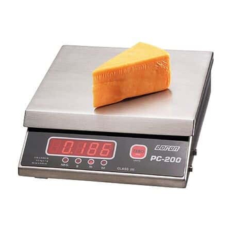
Section 2. Scale Operations Guide Fig. 1 PC200 Display Functions: The Model PC200 controls consist of a single ZERO button located under the main display. A 5 digit LED display is used to provide weight indications and operator messages describing scale operation. A single status annunciator, “NEG”, is used to display negative polarity. -
Page 6: Section 3. Setup And Calibration Guide
25) connector and attach the connector to your computer or printer. Calibration and Parameter Setup: 1) After applying power to the PC200, turn the scale over and remove the screw located next to the RS-232 connector. Place a thin blunt object through the hole and press straight down. -
Page 7: Analog Setup
5) If no other parameter changes are needed, press the “ZERO” button to select “donE Y”. Then press the hidden button to exit setup. Replace and seal the screw by the RS-232 connector. 6) If addition parameter changes are needed, refer to Chapter 4. Analog Setup: The following table shows the acceptable “Raw Counts”... -
Page 8: Section 4. Parameter Setup
Entering and Exiting Setup Mode: To enter the setup menu, apply power to the PC200, turn the scale over and remove the screw located next to the RS-232 connector. Place a thin blunt object through the hole and press straight down. -
Page 9: Changing Start Up Units
Changing Start up Units: The PC200 has been designed to allow the user the opportunity to make weighments in Pounds, Ounces or Grams. If there is desire to change the operating units, this change is possible without breaking the scale’s Weights and Measures seal. -
Page 10: Section 5. Setup Menus Explained
Half scale calibration 1/4 scale calibration 10% scale calibration NOTE: For maximum accuracy, Doran Scales recommends that all scales be calibrated at full capacity. When location or installation make it difficult to bring full capacity weights to the scale, calibration with as little as 10% of capacity is possible. -
Page 11: Auto Off Mode Ao
Auto Off Mode Auto Off Mode Determines how long the scale will wait before turning off. Off. Scale will run continually 60 minutes 30 minutes 20 minutes 10 minutes 5 minutes 4 minutes 3 minutes 2 minutes 1 minute Auto Zero Tracking # of displayed divisions that are automatically zeroed from displayed zero... -
Page 12: Data Output ( D.o. )
Basic dual print format. Includes metric weight. Enhanced data format. Output NOT Legal for Trade. Basic format for an Eltron SSP printer. Call Doran for details. Baud Rate b.r. Serial port transmission rate 1200 Baud (bits per second) 2400 Baud (bits per second) -
Page 13: Handshaking ( Hs )
Handshaking Communication Handshaking Software handshaking. Data is sent when ready. Transmission can be stopped by sending the scale an “xoff” (ASCII 19 or Ctrl-S). Transmission resumes by sending the scale an “xon” (ASCII 17 or Ctrl-Q). When “xon” is received, the scale will finish sending the data in progress at the time of “xoff.”... -
Page 14: Exit Setup Mode Done
Exit Setup Mode done Exit Setup Mode? No. Continue to next parameter. Yes. Exit Setup Mode Raw Counts Counts from A/D converter. Changes when weight is applied. ###### Raw counts from A/D converter View these numbers if calibration is unsuccessful. Refer to Section 3 for interpretation of these numbers. -
Page 15: Section 6. Data Communications
Section 6. Data Communications Introduction to data communications: In the PC200, data is sent to a printer or computer by using “asynchronous serial data communications.” Data is broken up and sent one piece at a time to the printer or computer. In spite of this apparent simplicity, a basic understanding of serial data communications is needed when setting up the PC200. -
Page 16: Printer Modes
When a “Ctrl-S” is received, the transmission of data is halted until a “Ctrl-Q” is received. To use this mode, the RTX line of the PC200 is tied to the TXD line of the receiving unit. -
Page 17: Data Output Format
Data Output Format: In order for the serial data sent from the PC200 to be useful, the data must me organized so that it is easy to read. To accomplish this, the PC200 arranges the displayed data with additional text to indicate the active units and to indicate the presence of motion during the reading. - Page 18 Dual print format (2P): The dual print mode provides the PC200 with the ability to print the current scale reading followed by the equivalent value in Kilograms. Displayed weight data with units. See fig. 1 for structure. Carriage return & line feed: ASCII characters 13 &...
-
Page 19: Bi-Directional Communications
Bi-directional Communications: The scale will respond to the following single letter ASCII commands. “W” initiates transmission of current weight data (if scale is stable). “U” changes the displayed weight units. “Z” zeroes the scale (if scale is stable). Note: In order to use bi-directional communications, the “HS” parameter must be set to “SF”. -
Page 20: Section 7. Specifications And Interconnect Data
Section 7. Specifications and Interconnect Data Specifications: Model PC200 2500d Resolution: Power Supply: Wall Transformer output: (scale input) 9VDC, 500mA Pos. (+) center Display: 5 digit LED. 0.56” high Displayed units: lb, oz and g Indicator Capacities: 2, 5 and 10 lbs... -
Page 21: Interconnect Data
Interconnect Data: PIN # TITLE + Excitation + Signal - Signal - Excitation Table 1: TB1 Load Cell Connections Serial Cable Assembly DB25 Female Connector w/ Software Handshaking Function Note: Signal GND 4 and 5 are shorted at the pcb Open, no connection at pcb DB9 Female Connector w/ Software... -
Page 22: Section 8. Troubleshooting
If problems persist and are not listed in the above troubleshooting table, please contact your Doran Scales authorized dealer. Resetting the scale: In the event that a power problem has disabled the scale, remove power, wait 15 seconds and restore power. -
Page 23: Error Messages
Error Messages: Error Message: What to do or check: “Er EP” The setup parameters loaded in nonvolatile memory have become corrupted. The scale requires reinitialization by a qualified scale technician. “rg Er” The calibration zero is out of range. Press zero to clear this error. Refer to the analog setup section for additional information.
Need help?
Do you have a question about the PC200 and is the answer not in the manual?
Questions and answers