Doran 7000 Instruction Manual
Hide thumbs
Also See for 7000:
- Instruction manual (5 pages) ,
- Instruction manual (45 pages) ,
- Operator's manual (8 pages)

Subscribe to Our Youtube Channel
Related Manuals for Doran 7000


Summary of Contents for Doran 7000
- Page 1 Model 7000 Model 7000XL Model 8000XL Digital Scale INSTRUCTION MANUAL DORAN SCALES, INC. 1315 PARAMOUNT PKWY. 1-800-262-6844 FAX: (630) 879-0073 http://www.doranscales.com MANUAL REVISION: 3.0 MAN0190 8/26/2002 Made in USA...
- Page 2 Table of Contents Table of Contents ..................1 Introduction ....................4 Quick Start User's Guide ................5 Fig. 1: Model 7000 Front Panel Layout ................5 Model 7000:..........................5 Fig. 2: Model 7000XL Front Panel Layout.................5 Model 7000XL:........................6 Fig. 3: Model 8000XL Front Panel Layout.................6 Model 8000XL:...........................6...
- Page 3 Data output format: .........................26 "F0" Format: ..........................26 "2d" Format: ..........................26 "SSP" format:..........................26 "Fg" Format: ..........................26 Table 2: Doran serial protocol....................27 Specifications and Interconnect Data ............. 28 Specifications:..........................28 Table 3: Scale Specifications.....................28 Interconnect Data:........................28 Table 4: TB1 Load Cell Connections ................28 Table 5: P2 Options Connections ..................29...
- Page 4 Troubleshooting..................34 General problem resolution:....................34 Resetting the scale parameters: ...................35 Resetting the scale:........................35 Scale Messages: ........................36 Error messages: ........................36 Replacement Part List................37 Warranty Statement..................41...
-
Page 5: Introduction
This scale uses state of the art technology to provide you with a low cost solution to the most demanding weighing applications. With ease of use and setup in mind, the scale is simple to set up and ready to use. The Model 7000, 7000XL, 8000XL offers many features. A few of these features are listed below: NTEP certification for Class III installations to 10,000d (CoC 99-129). -
Page 6: Quick Start User's Guide
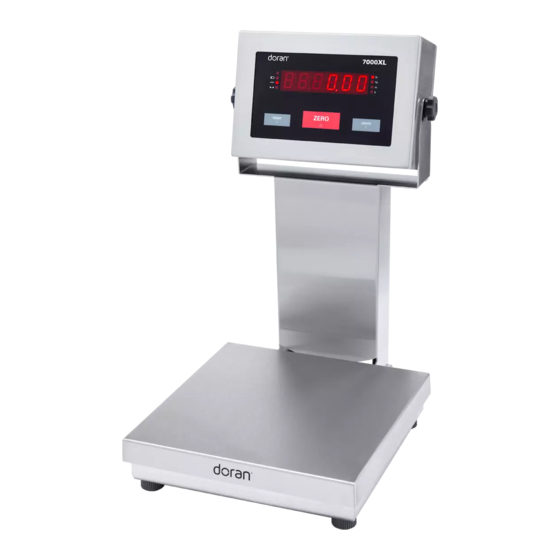
Fig. 1: Model 7000 Front Panel Layout Model 7000: The Model 7000 (Fig. 1) controls consist of the ZERO and optional UNITS buttons located under the main display. A six-digit LED display is used to provide weight indications, negative polarity (except lb/oz) and operator messages describing scale operation. -
Page 7: Model 7000Xl
Scale units are displayed on four annunciators located to the right of the main display. Power Up: Connect the Model 7000, 7000XL to a compatible power source. With the 8000XL, press and release ZERO to turn on scale. -
Page 8: Basic Weighing Operation
Be sure the AC power is not excessively noisy - this can occur if large inductive loads, such as solenoids or motors, are on the same power line. The Model 7000, 7000XL, 8000XL has a filtered power supply to reduce the effects of normal line noise, but they cannot limit severe fluctuations. -
Page 9: Units
PRINT button. The current weight will then be transmitted to the printer. The 7000XL, 8000XL, and 7000(optional) has a "Print on Demand" feature which stores a PRINT request until the scale is stable. Once stable, the scale transmits the current weight. -
Page 10: Quick Setup Guide
Quick Setup Guide Remove factory installed shipping jumper. ZERO ZERO P3B + Signal - Signal + Excitation - Excitation + Sense UNITS - Sense UNITS Remove JU7 and JU8 when connecting a 6- wire load cell. (JU7 and JU8 must be present CAL S3 when connecting to a 4-wire loadcell) Fig. -
Page 11: Fig. 5: Serial Communications And Remote Push Button Connections
2) The CAL switch S1 is a momentary push button located in the lower left corner of main PC. Board (see Fig. 4). On the 7000XL and 8000XL, the calibration switch can be accessed by removing the meter’s back cover. For the 7000 remove the Cal access panel located on bottom of indicator. -
Page 12: Capacity
(do not use CAL FS ). Then scroll to the exact weight by pressing CAPACITY to go higher or PRINT to go lower. This is not available on the Model 7000. -
Page 13: A/D Ranging
10% of capacity are more likely to have significant errors at full capacity than are scales calibrated at 25% or 50%. Doran Scales recommends that all scales be calibrated at full capacity whenever possible. 10% calibration should not be used when calibrating scales for legal for trade applications. -
Page 14: Parameter Setup
For Trade mode (“ ” = “ ”). This feature is not available on 7000 without the units push button option. To enter the calibration mode, power up scale while pressing the ZERO and the UNITS button at the same time. When the “... -
Page 15: Stepping Through The Menu Parameters
UNITS to go to the next menu item. Quick Review of Setup Parameters: The Setup parameters for the Model 7000, 7000XL, 8000XL may be quickly reviewed without entering in the Calibration and Parameter Setup Mode. Remove power and press and hold the ZERO button while you apply power. -
Page 16: Setup Menus Explained
Setup Menus Explained (In order of occurrence) Calibration Setup Menu CAP CAP CAL CAL AVg AVg A2t A2t nn nn. A . . A . SU0 SU0 2od 2od Pod Pod d. o . d. o . For. For. br. br. on on t. -
Page 17: Capacity Setup Menu
Capacity Setup Menu Capacity Select Menu CAP CAP Allows the selection of scale capacity. 2 pounds 5 pounds 6 pounds 10 pounds 15 pounds 20 pounds 25 pounds 25 25 30 pounds 50 pounds 60 pounds 1 0 0 100 pounds 1 5 0 150 pounds 200 pounds... -
Page 18: Calibration Menu
This feature is not available on 7000.) NOTE: For maximum accuracy, Doran Scales recommends that all scales be calibrated at full capacity. When location or installation make it difficult to bring full capacity weights to the scale, calibration with as... -
Page 19: Digital Filter Setup Menu
Digital Filter Setup Menu Averaging mode Avg Avg Determines the number of samples to average © Stabil-izer auto averaging. All readings are averaged. Display updates 10 times a second. Stabil-izer © auto averaging. All readings are averaged. Display updates 9 times a second. ©... -
Page 20: Motion Aperture Setup Menu
Motion Aperture Setup Menu Motion aperture * Determines how many divisions consecutive nn. A . nn. A . readings must change before the scale is considered in motion. 1 division change must be seen to enter motion. 3 division change must be seen to enter motion. 5 division change must be seen to enter motion. -
Page 21: Printer Data Output Setup Menu
Printer Data Output Setup Menu Data Output Mode (see page 25) d. o . d. o . Determines when serial data will be sent. Transmit on demand. Print when the PRINT button is pressed. t. o . d . t. o . d . C. -
Page 22: Serial Data Handshaking Setup Menu
Serial Data Handshaking Setup Menu Serial Data Output Handshaking Selects the type of serial data handshaking used. HS HS (See the Data Communication section for details) No handshaking is used. Data is sent when ready, receiving device (printer) must be fast enough to keep up with the data. -
Page 23: Push-Button Function Setup Menu
Push-button Function Setup Menu Push Buttons P. b . P. b . Configures the active push button functions. UNITS, PRINT enabled CP CP PRINT enabled only. UNITS enabled only. UNITS, PRINT disabled. Remote Push-button Configuration Menu Remote Push Button (P2 – pins 3 and 4) Configures the Remote Switch to perform one of r. -
Page 24: Unit On Timer (8000Xl Only)
Unit On Timer (8000XL only) td4 td4 Selects the time value that the unit will remain on Unit will remain on, On timer is off 30 second "On timer" 0. 5 0. 5 1 minute "On timer" 1 . 5 1.5 minutes "On timer"... -
Page 25: Data Communications
Data Communications Introduction to data communications: In the Model 7000, 7000XL, 8000XL data is sent to a printer or computer by using "asynchronous serial data communications." Data is broken up and sent one piece at a time to the printer or computer. In spite of this apparent simplicity, a basic understanding of serial data communications is needed when setting up the scale. -
Page 26: Printer Modes
"Ctrl-Q" is received. To use this mode, the RTX line of the scale is tied to the TXD line of the receiving unit. Refer to Doran RS-232 Training Technical Bulletin (MAN0214) for in depth coverage of this subject. -
Page 27: Data Output Format
Data output format: In order for the serial data sent from the scale to be useful, the data must be organized so that it is easy to read. To accomplish this, the scale arranges the displayed data with additional text to indicate the active units and to indicate the presence of motion during the reading. -
Page 28: Table 2: Doran Serial Protocol
<LF> line feed (hex 0A) (control-J) Scale changes units (hex 55) Zeros scale (hex 5A) Turns on serial handshaking (hex 11, ctrl-Q) scale output disabled Turns off serial handshaking XOFF (hex 13, ctrl-S) scale output enabled Table 2: Doran serial protocol... -
Page 29: Specifications And Interconnect Data
Specifications and Interconnect Data Specifications: Model: 7000 7000XL 8000XL Resolution: 10,000d in precision mode Sensitivity: 0.5 uV min. Load Cell Capacity: 0.5 mV/V to 3.5 mV/V Power Supply: 115/230VAC 50/60Hz 115/230VAC 50/60Hz 6V Battery Display: 6 digit LED. 0.56" high... -
Page 30: Table 5: P2 Options Connections
P2 Options Connections PIN # TITLE WIRE COLOR CODE White Remote Switch High White Remote Switch Ground Black RS232 Signal Ground Black Table 5: P2 Options Connections J1 Power Connections PIN # TITLE WIRE COLOR CODE Neutral Blue Ground Green Brown Table 6: J1 Power Connections P3 Keyboard Connections... -
Page 31: Fig. 7: Connector J2, Serial Cable Assembly
WHITE GREEN SHRINK SHIELD SHRINK BLACK Fig. 7: Connector J2, Serial cable assembly RS232 Output DB9 Female connector Function RXD/CTS Signal GND Table 8: Serial Output pin description Fig. 8: RS232 Output DB9 Connector (optional) -
Page 32: Fig. 9: Installation Of Emi / Rfi / Esd Protection Devices
Fig. 9: Installation of EMI / RFI / ESD protection devices. NOTE: Fig. 9 illustrates a 7000/7000XL/8000XL connected with a 4-wire load cell. When installing a 6-wire cell, remove shunts at JU7 and JU8. -
Page 33: Fig. 10: Jumpers And Connector Locations
Fig. 10: Jumpers and Connector Locations Jumper settings per model Jumper 7000 7000XL 8000XL In for 4 wire and Out for 6 wire loadcell connections In for 4 wire and Out for 6 wire loadcell connections JU10 JU20 JU21 LEFT TWO PINS... -
Page 34: Ma Analog Output (Optional)
4-20mA Analog Output (optional) Introduction The 4-20mA Analog Output Option is used to provide an analog output that is proportional to the weight on the scale platform. Because of the inherent noise immunity present in a current loop, an isolated 4-20mA analog output is ideal for use in noisy environments. -
Page 35: Troubleshooting
Averaging to a higher setting to stabilize the reading (see Parameter Setup section). If you are still experiencing a problem with your scale, or if the problem you are having is not covered in the above list, please contact your Doran Scales authorized dealer. -
Page 36: Resetting The Scale Parameters
Resetting the scale parameters: If at some point the Model 7000, 7000XL, 8000XL, user wishes to return the setup parameters to factory default, follow these steps. WARNING: Defaulting the scale will require recalibration. Enter Cal mode by using Cal access feature or by pressing the CAL button. -
Page 37: Scale Messages
Scale Messages: Message Meaning " " The scale has successfully completed the requested action. donE Function complete. " " The requested action has been canceled prior to completion. Abort Aborted function. " " The scale has successfully store and verified parameter SAVEd Parameter value saved. -
Page 38: Replacement Part List
Replacement Part List SUB0408 7000/7000XL Main PCB Assembly, 115 VAC SUB0408-1 7000/7000XL Main PCB Assembly, 230 VAC PCA0223 8000XL Main PCB Assembly, 115 VAC PCA0223D 8000XL Main PCB Assembly, 230 VAC SUB0013D 7000 Zero Switch Assembly Pushbutton switch with cable, S/S boot, & PCB connector... - Page 39 LED0016 8000XL LED, Units Indicator One red 4 segment LED LBL0173-A Capacity Labels FUS0019 Fuse, 1/4 Amp, Slo-Blo 7000/7000XL(115VAC), 8000XL(230VAC) Used in P/N SUB0408, PCA0223D FUS0020 Fuse, 1/2 Amp, Slo-Blo 8000XL(115VAC) Used in P/N PCA0223 FUS0021 Fuse, 1/18 Amp, Slo-Blo 7000/7000XL(230VAC)
- Page 40 SUB0235 Calibration Port Cover Assembly Includes cover, gasket & screws SUB0438 7000/7000XLGasket & Screw Set, Rear Panel 3 standard, 1 cross-drilled 10-32 bolts, 4 rubber bonded metal washers and 1 rear gasket. SUB0398 8000XLGasket & Screw Set, Rear Panel 3 standard, 1 cross-drilled 10-32 bolts, 4 rubber bonded metal washers and 1 rear gasket.
- Page 41 Calibration/Units Switch Replacement Kit Includes switches and caps IND0006 Power Cord Chosorb MSC0085 7000/7000XL Scale Veil MSC0102 8000XL Scale Veil 70OPTX 7000 Analog 4-20mA Output 7XOPTX 7000XL Analog 4-20mA Output 8XOPTX 8000XL Analog 4-20mA Output (Passive only) 30OPT36 6-digit Remote Display...
-
Page 42: Warranty Statement
Warranty Statement...
Need help?
Do you have a question about the 7000 and is the answer not in the manual?
Questions and answers