
Related Manuals for Doran 2200G


Summary of Contents for Doran 2200G
- Page 1 2200 2200B 2200CW 2200G INSTRUCTION MANUAL DORAN SCALES, INC. 1315 PARAMOUNT PKWY. BATAVIA, IL 60510 1-800-262-6844 FAX: (630) 879-0073 http://www.doranscales.com MANUAL REVISION: 5.0 MAN0253 2/29/2008...
-
Page 3: Table Of Contents
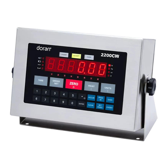
Fig. 1: Model 2200 Front Panel Layout ..............9 Fig. 2: Model 2200B Front Panel Layout ..............9 Fig. 3: Model 2200CW Front Panel Layout ............. 10 Fig. 4: Model 2200G Front Panel Layout..............10 LED Annunciators ...................... 11 Power Up and Power Down ..................12 Software Part Number and Revision Level.............. - Page 4 Display ID Values (2200 series, one product setting)..........22 Keypad Entry of ID Values (2200 series, one product setting) ........22 Barcode Entry of ID Values ..................22 Setting Time and Date....................23 Battery Operation ..................24 Installation Guide ..................25 Fig.
- Page 5 Remote Product ID Entry and Recall:................. 61 Remote Product Description Entry and Recall: ............61 Remote Tare Entry and Recall: .................. 61 Table 2: Doran serial protocol ................. 65 Specifications and Interconnect Data ............. 66 Specifications: ......................66 Table 3: Scale Specifications .................. 66 Interconnect Data:......................
- Page 6 Digital Output Specifications: ..................82 Wired Ethernet Option ................84 Fig. 24: RJ-45 Ethernet connector................84 Specifications: ......................84 Doran Wired Ethernet Configuration Guide ........... 85 Module LED Description..................... 87 Wireless 802.11b Ethernet Option ............88 Fig. 25: Wireless Ethernet Antenna................. 88 Features and Applications..................
- Page 7 USB Option....................101 Fig. 26: USB option board ..................101 USB Windows Drivers ....................101 Installation For Windows XP: ................... 101 Removal For Windows XP: ..................104 Installation For Windows 2000: ................105 Removal For Windows 2000: ................... 109 Dimension Software ................111 Description: ......................
-
Page 8: Introduction
Please be sure to read the entire manual to ensure you obtain all the benefits that the 2200 series can provide. If any questions arise, please feel free to contact the Doran Scales Technical Support Department at 1-800-262-6844. -
Page 9: Unpacking Your Scale
Unpacking Your Scale Before unpacking your Doran scale, please read the instructions in this section. Your new scale is a durable industrial product, but it is also a sensitive weighing instrument. Normal care should be taken when handling and using this product. Improper handling or abuse can damage the scale and result in costly repairs that will not be covered by the warranty. -
Page 10: Scale Operation
Scale Operation Fig. 1: Model 2200 Front Panel Layout Fig. 2: Model 2200B Front Panel Layout... - Page 11 UNITS TARE [ ON/OFF ] PROD ACCUM OVER UNDER ENTER CLEAR POINT Fig. 3: Model 2200CW Front Panel Layout 1 2 3 4 5 6 7 8 2200G ZERO BATT GROSS ZERO PRINT UNITS TARE [ ON/OFF ] PROD ACCUM...
-
Page 12: Led Annunciators
ID being edited. 2200G only, the 8 large yellow led indicators above the main display are used to indicate: setpoint output status during weighing mode or the current setpoint, preact or ID being edited. -
Page 13: Power Up And Power Down
2200CW UNDER ACCEPT OVER GROSS ZERO TARE PRINT UNITS [ ON/OFF ] PROD ACCUM OVER ENTER CLEAR UNDER POINT Power Up and Power Down Connect the indicator to a compatible power source and the indicator will turn on. For scales with the battery option: To turn on the scale, press and release the ZERO button. -
Page 14: Push Button Tare
value will remain in memory. The indicator is equipped with a Zero on Demand parameter, which saves the ZERO push button command and zeros the scale upon the next stable reading. This option may be activated during the scale setup procedure. NOTE: On 2200B models configure for Batch Operating mode. -
Page 15: Toggle Gross And Net Modes
Using Doran’s optional barcode scanner, scan the desired barcode. The display will read SAVEd to indicate the scanned tare weight is saved. The display will flash the new tare weight scanned from the barcode. No special serial commands are needed prior to the weight data in barcode value. -
Page 16: Recall And Edit Data Output Formats
push button command and transmits data upon the next stable reading. This option may be activated during the scale setup procedure. The indicator also has several automatic print options. See the Data Communication Section for details on Further configuration. NOTE: On 2200B models configure for Batch Operating mode. The PRINT button is disabled when batch sequence is running. -
Page 17: Barcode Entry Of Setpoint Values
The annunciators below the main display indicate which setpoint is currently displayed. Using Doran’s optional barcode scanner, scan the desired barcode. The display will read SAVEd to indicate the scanned setpoint weight is saved. The display will flash the new setpoint weight scanned from the barcode. No special serial commands are needed prior to the weight data in barcode value. -
Page 18: Barcode Entry Of Preact Values
UNITS and PRINT to scroll through the eight available preacts. The annunciators below the main display indicate the current preact. Using Doran’s optional barcode scanner, scan the desired barcode. The display will read SAVEd to indicate the scanned preact weight is saved. The display will flash the new preact weight scanned from the barcode. -
Page 19: Display Check Limit Values (2200Cw)
The top light bars and the main display will indicate which check limit is being displayed(High, over, under, Louu). Using Doran’s optional barcode scanner, scan the desired barcode. The display will read SAVEd to indicate the scanned weight is saved. -
Page 20: Clear Accumulator And Counter
Clear Accumulator and Counter Press the ACCUM button to enter the accumulator and counter recall mode. The display will show Accunn followed by the accumulated weight in the units currently selected in the weigh mode. Then Countr will be displayed followed by the counter value. Press CLEAR to clear the accumulator and counter values. -
Page 21: Product Size Menu (2200Cw)
Check Way Software (optional) The Check Way optional software for management of new and existing product ID’s. Contact Doran Scales sales department for additional information on this option. Entering New Product ID number (2200CW, 250 product setting) Enter a 1 to 6 digit value, then press PROD ID. The display will momentarily show NEUU then Id. -
Page 22: Recall Existing Product Id (2200Cw, 250 Product Setting)
Recall Existing Product ID (2200CW, 250 product setting) Press PROD ID to enter the Product ID recall mode. The display will show Id, followed by the currently active Product ID number. To select another stored ID number, enter the preexisting ID number, then press ENTER. The display will read SaVed to indicate the Check Limits, Tare weight, Product Description String, Accumulator and Counter fields associated with that Product ID number are active. -
Page 23: Display Id Values (2200 Series, One Product Setting)
The display will confirm by showing the barcode value. To exit the ID edit mode press ID. 2. When the scale is in the normal weighing operation. Use the Doran’s optional barcode scanner to scan in a barcode value that begins with a numeric character. -
Page 24: Setting Time And Date
------ to represent the barcode value. To exit the ID edit mode press ID. 4. When the scale is in the normal weighing operation. Use the Doran’s optional barcode scanner to scan in a bar code value that begins with a numeric character. -
Page 25: Battery Operation
Battery Operation Indicators with the battery option installed are equipped with an internal rechargeable sealed lead-acid battery and charging circuit. The scale is designed to run continuously for 50 hours (with one 350 ohm load cell) on a fully charged battery. To significantly extend this battery life, be sure the Unit On Timer parameter is enabled, which will power down the scale automatically after a period of non-use. -
Page 26: Installation Guide
Installation Guide + Signal (Red) - Signal (White) + Excitation (Green) - Excitation (Black) + Sense (Blue) - Sense (Brown) CAL S1 Calibration Mode Remove JU7 and JU8 when connecting a 6-wire push button load cell. (JU7 and JU8 must be present when connecting to a 4-wire load cell) Fig. -
Page 27: Load Cell And Power Connections
Load Cell and Power Connections Load cell connections are made through terminal block “TB1” located at the bottom center of the main board (see Fig. 6). The power cord connects to terminal block “J1” adjacent to the transformer (see Fig. 7). These connections are accessible by removing the rear cover. -
Page 28: Calibration Mode
Calibration Mode To calibrate the 2200 series indicators, you must access the setup mode. Any of the three methods below can be utilized. Power–up Front Panel Setup Mode Access To enter the calibration mode, power up the indicator while pressing and holding the ZERO and the UNITS buttons. -
Page 29: Select Scale Resolution
Select Scale Capacity When the setup mode is accessed, the first parameter displayed is the capacity parameter. The capacity parameter toggles the display between CAP Aj and the current capacity. The capacity can be expressed in lb or kg. The units annunciator to the right of the weight display will indicate either lb or kg. - Page 30 Scales calibrated at 2% of capacity may have errors at full capacity than scales calibrated at 25% or 50%. Doran Scales recommends that all scales be calibrated at full capacity whenever possible.
-
Page 31: A/D Range Troubleshooting
A/D Range Troubleshooting On scales with factory installed platforms, the zero and span will lie within permissible limits. The allowable load cell signal input range is from 0.283 mV/V to 5 mV/V. 1) Enter the calibration mode. 2) Press PRINT until in the A/D raw counts are displayed. 3) Remove all items from the platform and record the dead load raw counts reading. -
Page 32: Parameter Setup Mode
Parameter Setup Mode The 2200 series provides many parameters that allows you to customize the operation of your 2200 indicator to meet your application’s needs. To access these parameters the setup mode must be accessed, which can be entered using any of the three methods below. -
Page 33: Stepping Through Menu Parameters
Stepping Through Menu Parameters Once the Calibration and Parameter Setup Mode has been entered, you may step through the menu by pressing UNITS or PRINT. Press CLEAR button to jump to end of menu section. Some items in the menu contain sub menus, which can be entered by selecting yes by pressing ZERO and then UNITS. -
Page 34: Calibration And Audit Counters
Calibration and Audit Counters When entering calibration mode, the parameter audit counter and the calibration audit counter will momentarily be displayed. The parameter audit counter only increments when CAP, Cnt by, A2t, nn.A., SU0, oP values are changed. The calibration audit counter increments when a successful zero calibration and span calibration are performed. -
Page 35: Parameter Configuration
Parameter Configuration Calibration Setup Menu CAp aJ Cnt by nn.A. d.o. For. Fo2. 0.00002 t.o.d. A.P.1 A.P.2 995000 5000 A.P.3 C.P. 14.4 A.P.b 19.2 A.P.5 28.8 xxxxxx UnitS P.b. PASS lb-oz 999999 Prod C.o. S.o. dEft xxxxxx donE 4nnA 20nnA out 1 out 2 dEf2... -
Page 36: Capacity Setup Menu
Capacity Setup Menu Capacity Adjustment Menu CAP Aj Allows the selection of scale capacity. 1 - 999000 1 lb / kg to 999,000 lb / kg NOTE: Capacities > 60,000 lb, oz units are disabled. Capacities > 2000 lb, grams units are disabled Capacities >... -
Page 37: Digital Filter Setup Menu
Digital Filter Setup Menu Averaging mode Determines the number of samples to average © Stabil-izer auto averaging. All readings are averaged. Display updates 10 times a second. Stabil-izer © auto averaging. All readings are averaged. Display updates 9 times a second. Stabil-izer ©... -
Page 38: Motion Aperture Setup Menu
Motion Aperture Setup Menu Motion aperture * Determines how many divisions consecutive nn.A.* readings must change before the scale is considered in motion. 0.5 division change must be seen to enter motion. 1 division change must be seen to enter motion. 2 division change must be seen to enter motion. -
Page 39: Printer Data Output Setup Menu
Printer Data Output Setup Menu Data Output Mode d.o. Determines when serial data will be sent out of serial port 1. Transmit on demand. The current stable weight is transmitted whenever the PRINT button is pressed, t.o.d. a remote PRINT button is pressed, or a print request is received via communications options. -
Page 40: Output Formats, Port 1
Output Formats, Port 1 Data Output Format of Serial Port 1 For. Defines the serial data transmitted. (see Data output format) Basic output format (8,n,1) Enhanced output includes grade status. Live Scale (Virtual) Display format ( set d.o. to C.P.) Modbus output format Select Custom Data String 1 (user defined print string) Select Custom Data String 2 (user defined print string) -
Page 41: Handshaking Setup Menu
Handshaking Setup Menu Serial Data Output Handshaking (Port 1 only) Selects the type of serial data handshaking used. (See the Data Communication section for details) Software handshaking. The software handshaking option activates Bi-directional RS232 communications. Refer to the communications section for details. Disables all RXD communications. -
Page 42: Units Conversion Setup Menu
Units Conversion Setup Menu Convert Select Modes Determines which units selections will be active. Do not enter Convert selection menu. Enter Convert selection menu. pounds menu lb is active lb is non active kilograms menu kg is active kg is non active ounces menu oz is active oz is non active... -
Page 43: Push-Button Function Setup Menu
Push-button Function Setup Menu P.b. Configures push button and remote push buttons. Do not enter push button selection menu. Enter push button selection menu. GROSS NET push button menu pb is active pb is non active ACCUM push button menu pb is active pb is non active (disables accumulator) OVER &... -
Page 44: Operating Mode Setup Menu
Remote pb = STOP (2200B only) PASS CD Pass Code Entry Enter a non-zero number to enable 000000 the password feature. Operating Mode Setup Menu Operating mode oP * Activates the Legal for Trade mode. Standard operation (Audit Trail) Legal for Trade, Handbook 44 (NIST) (Audit Trail, Audit counters shown) Legal for Trade Switch mode, Handbook 44 (NIST) and Measurement Canada compliant. -
Page 45: Product Size Menu (2200Cw)
Product Size Menu (2200CW) Prod Selects between 1 or 250 product memory. Up to 250 products are stored under Product ID number in memory. Limits indicator to one product stored in memory. Checkweighing Operation Menu (2200CW) Check Weighing Operation C.o. Configures the check weighing operating mode. -
Page 46: Setpoint And Preact Operation Menu
Setpoint and Preact Operation Menu Setpoint Operation Menu S.o. Configures each of the individual Setpoint operating mode. Do not enter Setpoint Operation menu. Enter to selected and adjust individual setpoint operational mode. Setpoint 1 mode menu Setpoint off Active High (wt > setpt Active Low (wt <... -
Page 47: Threshold Level Menu
Setpoint 7 entry menu Setpoint off Setpoint 8 entry menu Setpoint off Threshold Level Menu Threshold Level Entry Selects a percent threshold of Capacity when AP2 and latching setpoint operation is active. 0.1 - 9.9 +0.1% to +9.9% of capacity. Default setting is 1% Default all Scale Parameter settings dEFt Default Calibration and Parameter settings. -
Page 48: Calibration And Parameter Menu Exit
o1 SP3 Setpoint 3 used for output logic. o1 SP4 Setpoint 4 used for output logic. o1 SP5 Setpoint 5 used for output logic. o1 SP6 Setpoint 6 used for output logic. o1 SP7 Setpoint 7 used for output logic. o1 SP8 Setpoint 8 used for output logic. -
Page 49: Batch Commands (2200B)
Batch Commands (2200B) Batching command list (2200B model only) Command Specifies command to be executed at each step up to 100 steps. See Instruction Batch Command Explained for a detailed explanation of each command. Causes no operation, execution simply passes to the next instruction in the list (useful for allowing insertion of a command in the future). - Page 50 Causes a local repeat to a preceding line containing the START OF LOCAL REPEAT command. Loop for the number of times specified. LOCAL REPEAT 00 = loop indefinitely. An "lC Rep" message will be displayed if the 00-99 operation was successful. Waits for DIN 1 input to become momentarily active.
- Page 51 JUMP TO LINE IF Jump to a selected line, if setpoint is active. SETPOINT 1-8 ACTIVE Causes the indicator to jump to a selected line when DIN 1 is active, if not active, will continue to the next instruction in the list. Press START JUMP TO LINE IF DIN1 ACTIVE button to bypass this command.
-
Page 52: Default Batch Sequence
Default Batch Sequence Line Command Description Number Instruction CLR ALL OUTPUTS All Outputs are non-active. WAIT UNTIL STABLE Wait until indicator is stable. PUSH BUTTON ZERO Push button Zero. SET OUTPUT 1 Output 1 is active. WAIT FOR SETPOINT 1 Wait until setpoint 1 is active. -
Page 53: Learning Preact
Learning Preact The Learning Preact calculations are performed when the batch command "WAIT FOR LEARNING PREACT 1-8 SAMPLE" is processed. The command waits for a stable weight to be used as a sample in calculating a Learning Preact value. The Learn Preact formula is shown below in Fig. -
Page 54: Data Communications
Data Communications Standard Print String Formats The Scale provides eight predefined print strings that are outputted when a manual print, auto print or print function is executed. The exact contents of the predefined print strings and custom data string configuration is shown below. Print String Description Standard Output Format, Prints current... - Page 55 Format 1, Prints current weight and the <STX> Start of Text (02h) highest setpoint number that is active <p> Weight Polarity (Grading number). Negative weight printed as “-”, positive weight are printed as a <STX><p><xxxx.xx><SP><uu><SP> space (20h). <CWS><MOT><CR><LF> <xxxx.xx> Weight Data fixed field of 6 digits plus decimal.
- Page 56 Live Scale (Virtual) Display format, <"^"> caret (5Eh) Prints current weight, units, <p> Weight Polarity annunciators, checkweigh status, Negative weight printed as “-”, and output status. positive weight are printed as a space (20h). <"^"><p><xxxx.xx><ut><an><chk1-4> <xxxx.xx> Weight Data fixed field <chk5-8><out1-4><out5-8><ETX>...
- Page 57 Custom Data String 1 (\x\w \u \m\r\l) <STX> Start of Text (02h) <p> Weight Polarity <STX><p><xxxx.xx><SP><uu><SP> Negative weight printed as “-”, <MOT><CR><LF> positive weight are printed as a space (20h). Sample Print String <xxxx.xx> Weight Data fixed field ±--10.05-lb of 6 digits plus decimal. In overload, or underload “-------”...
- Page 58 Custom Data String 3 (\xID:\i \w \u \m\r\l) <p> Weight Polarity Comma-delimited format / CSV Negative weight printed as “-”, positive weight are printed as a <STX><”ID:”><ADR><p><xxxx.xx><SP>< space (20h). <xxxx.xx> Weight Data fixed field uu><SP><MOT><CR><LF> of 6 digits plus decimal. In overload, Sample Print String or underload “-------”...
-
Page 59: Custom Data String Configuration
Custom Data String Configuration Programming the custom data strings requires the use of Doran’s Dimension Windows program or a terminal program and a data communications option. The custom data strings can be configured from serial port 1, port 2 or any communications option. -
Page 60: Custom Data String Control Characters
Custom Data String Control Characters Accumulated Weight (polarity (<sp> or “-”), 8 digits with leading spaces, and decimal point) Accumulated Weight (polarity ("0" or “-”), 8 digits with leading zeros, and decimal point) Accumulation Counter (7 digits, leading spaces) Accumulation Counter (7 digits, leading zeros) Current Weight (polarity (<sp>... -
Page 61: Remote Setpoint / Preact / Limit Entry And Recall
Preact Weight (x = 1-8, Preact field location)(polarity (<sp> or “-”), 6 digits, and decimal point) Time (Military) HH:MM (HH = 00-23)(MM = 00-59) Time (Military) HH:MM:SS (HH = 00-23)(MM = 00-59)(SS = 00-59) Time (Civilian) HH:MM "AM"/"PM" (HH = 01-12)(MM = 00-59) Time (Civilian) HH:MM:SS "AM"/"PM"(HH = 01-12)(MM = 00-59)(SS = 00-59) Time "AM"... -
Page 62: Remote Product Id Entry And Recall
250. The Product Description string will be stored in the same array field as the current Product ID. For the 2200, 2200B, 2200CW or 2200G with a setting of Prod set to 1. Only one Product Description string can be store. - Page 63 tell the indicator to expect a tare weight value. Note: For the model 2200CW set for 250 product memeory. The Tare value will be stored in the same array field as the current Product ID. A total of 250 Tare Values can be stored, one for each Product ID. ET<tare>...
- Page 64 Command Scale output Response (TXD) Description (RXD) Will respond with current selected data string Transmits data out TXD1 (Port1) transmitted from serial port 1. (No transmission W or w will occur if scale is in motion.) Will respond with Custom Data String Transmits Custom Data String number...
- Page 65 Read weight value in Preact number Preact weight value. x = 1 to 8, 0 = current Preact number See Remote Preact Entry and Recall. * (acknowledgment, port 1 only) Enter weight value in Preact number Display will show an "SAVEd" to indication that x = 1 to 8, 0 = current Preact number the Preact value has been successfully saved See Remote Preact Entry and Recall.
- Page 66 When in the Batch mode, Scale will * (acknowledgment, port 1 only) pause at current step in the batch Display will show an "PAUSE" to indication that (2200B only) program. batch relay outputs Batch program has paused. inactive. Table 2: Doran serial protocol...
-
Page 67: Specifications And Interconnect Data
Specifications and Interconnect Data Specifications: Model: 2200/2200G 2200B 2200CW Resolution: 200d to 50,000d Sensitivity: 0.5 uV min. Load Cell Capacity: 0.283 mV/V to 5 mV/V Power Supply: 115 / 230VAC 50/60Hz 6V Battery Optional Display: 6 digit LED. 0.56" high... - Page 68 P2 Option Connections Pin # Function Wire Color Port 1 RXD1 (RS232) White Port 1 TXD1 (RS232) Ground Black Switch 1 Input White Switch 1 Input White Port 2 RXD2 (RS232) Scanner White Port 2 TXD2 (RS232) Scanner Ground Black +VCC (unregulated, +12Vdc) Scanner positive supply Table 5: P2 Options Connections...
- Page 69 J6 External Supply Connections (optional) Pin # Function 8-24 Vdc input Ground Table 7: J6 External Supply Connections J1 Power Connections PIN # TITLE WIRE COLOR CODE Neutral Blue or White Ground Green or Green/Yellow Brown or Black Table 8: J1 Power Connections Fig.
- Page 70 Fig. 12: Jumpers and Connector Locations Jumper settings per model 2200 2200B 2200CW 2200G Jumper 2200 2200B 2200CW 2200G (battery) (battery) (battery) (battery) In for 4 wire and Out for 6 wire load cell connections In for 4 wire and Out for 6 wire load cell connections...
-
Page 71: Fuse Replacement
Fuse Replacement: The Scale's line fuse (F1) is located next to the power terminal (J1). Make sure power is off, before replacing the fuse. Remove the fuse cap by unscrewing it counter clockwise, then pull the fuse out of the socket and insert the new fuse in socket (see FIG. 13). Then screw the fuse cap back on the socket and apply power to the scale. -
Page 72: 4-20Ma Analog Output Option
The 4-20mA output can be forced to 4mA and 20mA in the test mode parameter to aid in calibration without the use of test weights. If, after calibration, the Doran 4-20mA output needs adjustment, see the test mode parameter for adjustment instructions. -
Page 73: Operation And Output Signals
Operation and Output Signals There is no effect on scale operation when the 4-20mA Analog Output Option is installed. The only exception to this is on models with battery option where battery life will be reduced by 50% when the 4-20mA option is set to the active mode. To increase battery life back to normal, set option output for passive mode The output signals are as follows: The 4-20mA output is based upon the current displayed weight... -
Page 74: Rs485 Communications Option
RS485 Communications Option The scale offers an RS485 data communications option. RS485 communications are similar to RS232 except that RS485 provides better noise immunity, it is suited to longer cable distances, and it will allow multiple scales to be attached to the same data line. RS485 achieves its performance advantage over RS232 by utilizing a differential input and output. -
Page 75: Rs485 Setup
Once the scale address is set, select the "Data Output Mode." Doran Scales recommends against using the Continuous Print Mode with RS485 because the buffer will fill up quickly requiring frequent readings of the buffer. - Page 76 RS485 Option Specification Maximum Cable length 4,000 ft. Maximum number of scales per bus 32 nodes Maximum Number of Print commands that 130 with Print Output can be stored in Print Buffer (2000 bytes) format = "FO" Bus common mode range +7 volts RS485 node load impedance 12K ohms...
- Page 77 Jumper settings for RS485 line Function Jumper 120 ohm line to line Termination Resistor 1K ohm pull up Bias Resistor 1K pull down Bias Resistor Table 12: RS485 Termination Resistors In general, JU5 should be inserted at the terminating ends of a long RS-485 bus. Scales (nodes) located between these ends do not need this resistor.
-
Page 78: Internal Relay Option
Internal Relay Option Fig. 17: Digital Output TB4 Terminal The Internal Relay Option (EXOPT106) allows up to four relays to be mounted inside the scale's enclosure. The relay control is described in Parameter Setup Section. This section discusses the installation and wiring of the relay controls. Three types of relays are available for use with the Internal Relay Option –... -
Page 79: Internal Relay Setup
Relay Specifications: 6VDC Mechanical Relay, 10A 250VAC / 30VDC. Doran part number: EXOPT195 AC Solid State Relay, 2A 100-240VAC. Doran part number: EXOPT109 DC Solid State Relay, 2A 5-48VDC. Doran part number: EXOPT110... -
Page 80: Step-Up Relay Circuit
Channel Terminal Conductor Color TB201 – NC Relay 1 TB201 – COM White (OUTPUT 1) TB201 – NO Green TB202 – NC Black Relay 2 Blue TB202 – COM (OUTPUT 2) TB202 – NO Brown Grey TB203 – NC Relay 3 TB203 –... -
Page 81: External Relay Box Option
External Relay Box Option The External Relay Box Option (EXOPT107) consist of a +6V Power Supply and up to eight DIN rail mounted relay modules, see Fig 20. The Relay Box is a NEMA4X polystyrene enclosure (10" W x 7" H x 6" D) with a clear cover. The housing has knock- out plugs with sizes of 7/8", 1-1/8", 1-1/2"... -
Page 82: External Relay Setup
Fig. 21: Knock-out Plugs External Relay Setup: The Relay module is offer with three different types of relays, mechanical and solid state (AC or DC). The mechanical relay’s output consists of terminal 4 - common (COM), terminal 3 - normally open (NO), and terminal 2 - normally closed (NC) (see FIG 22). The mechanical relay (OMRON G2R-1-SN) is rate for a maximum of 10A @250VAC or 10A @30VDC. -
Page 83: Digital Output Setup
Module Terminal Conductor Color Relay 1 1(-) A2 Brown Relay 2 1(-) A2 Relay 3 1(-) A2 Orange Relay 4 1(-) A2 Yellow Relay 5 1(-) A2 Green Relay 6 1(-) A2 Blue Relay 7 1(-) A2 Purple Relay 8 1(-) A2 Grey Power Supply... - Page 84 suppression diode and a 10K ohm pull-up resister connected to +V. Maximum current for single output is 200mA. Total current available for all outputs using the internal +6V supply is 280mA Total current available for all outputs using an external supply is 600mA. External power supply voltage range at +V is 5 - 35VDC.
-
Page 85: Wired Ethernet Option
Wired Ethernet Option The Wired Ethernet Option (EXOPT101) connects your Excel Series scale to an Ethernet network. The Digital Output board equipped, with the Ethernet module, installs inside the washdown safe enclosure. The NEMA4X sealed RJ-45 Ethernet connector is bulkhead mounted to the rear panel of the indicator (See Fig 24). The Wired Ethernet Option auto senses 10/100Base–T networks, so network configuration is simple. -
Page 86: Doran Wired Ethernet Configuration Guide
IP address. To configure a Static IP address, follow the instructions below. Run the dgdiscvr.exe software provided with the Doran Scale on a PC connected to the network and on the same subnet. When this program is executed, all Doran Wired and Wireless Ethernet devices connected to your network will be listed. - Page 87 If you wish to have a Static IP address, click on Network under the Configuration header on the left. To configure to a Static IP address, click on Use the following IP address radio button and fill in the required network IP address fields. The IP Address field contains the current IP address assigned by the DHCP server.
-
Page 88: Module Led Description
the device settings will be shown in the Details window on the left of the program window. The device will show that it is configured and the IP address status will be shown to be DHCP or Static. Be sure that the device does not have a red explanation mark next to it in the main window. -
Page 89: Wireless 802.11B Ethernet Option
Wireless 802.11b Ethernet Option The Wireless Ethernet Option (EXOPT102) connects your Excel Series scale to an wireless network. The Digital Output board equipped, with the Wireless Ethernet module, installs inside the washdown safe enclosure. The antenna is bulkhead mounted to the rear panel of the indicator and sealed for harsh environments as well, see Fig 25. The Wireless Ethernet Option lets you put your scale almost anywhere in the building, without the cost and hassle of running cables. -
Page 90: Specifications
Specifications: Hardware: Bulkhead mount 2.4 GHz Dipole Antenna Network Interface: 802.11b Ethernet Protocol Data rates up to 11Mbps Universal IP address assignment Static IP DHCP 2.4 GHz Frequency 16 dBm Transmitting Power Receiving Sensitivity -82 dBm at 11 Mbps -92 dBm at 1 Mbps Operating Temp. -
Page 91: Doran Wireless Ethernet Configuration Guide
Configure the customer supplied Wireless Access Point to broadcast the SSID. Disable any WEP or WPA security in your WAP. Turn on the Doran Scale with the Wireless Ethernet option installed. Be sure to have the scale near the WAP to prevent any interference with communication while configuring the Wireless Ethernet option. - Page 92 seen below. Click on Network under the Configuration header on the left. To configure to a Static IP address, click on Use the following IP address radio button and fill in the required network IP address fields. The IP Address field contains the current IP address assigned by the DHCP server.
- Page 93 64 bit encryption (10 hex digits) or 128 bit encryption (26 hex digits). Use the encryption key or sign on that the WPA device will use. Once changes are made, click Apply to save the changes. WARNING: Make sure to write down and save the security settings for the Doran...
-
Page 94: Module Led Description
At this point, you will have to reconfigure your WAP to the security settings to allow the Doran Wireless Ethernet option to communicate with the WAP. You may have to reboot your WAP after the changes are made. If the same SSID and security settings are not implemented, communication will fail. -
Page 95: Doran Wireless 802.11B Ethernet Option
Please fill out this form to provide the customer’s wireless access point configuration. Filling out this form will enable Doran to configure your Wireless Ethernet Option at our factory. Configuration at Doran will save you time and effort configuring the Wireless Ethernet Option when it arrives at your facility. -
Page 96: Wpa - Pre-Shared Key
WPA – Pre-Shared Key The passphrase is 8 to 63 characters long. WPA – Authentication User Name: Password: Doran Ethernet Option Factory Configuration Data Sheet IP Address Configuration (check one only) Dynamic IP Address (typical) Static IP Address Dynamic IP Address No further information is required. -
Page 97: Connecting To A Scale Through A Web Page
Connecting to a scale through a web page While connecting to a scale through a web page, the following window may be displayed. Type the following to login to the scale: Username: root Password: dbps... -
Page 98: Defaulting Wired And Wireless Ethernet Modules
WAP without any security enabled. Once defaulted, the module needs to be configured for proper network communications. Run the dgdiscvr.exe software provided with the Doran Scale on a PC connected to the network. When this program is executed, all Doran Wired and Wireless Ethernet devices connected to your network will be listed. - Page 99 Click on GPIO under the Configuration header on the left Reconfigure Pin 1 through Pin 5 to In and click apply. Click on Serial Port under the Configuration header on the left.
- Page 100 Click on Custom and click Apply. Click on Basic Serial Settings at the bottom of the display window. You may have to scroll down to see this selection. Change Flow Control to none and confirm the other settings are as shown above and click apply.
- Page 101 Select ‘Send Data only under any of the following conditions:’ by clicking on the selection check box. Then select ‘Send after the following number of idle milliseconds’ and set the ms setting to 50. You can now reconfigure the Wireless and Wired Ethernet Module.
-
Page 102: Usb Option
USB Option Fig. 26: USB option board USB Windows Drivers Virtual COM port (VCP) drivers cause the USB device to appear as an additional COM port available to the PC. Application software can access the USB device in the same way as it would access a standard COM port. - Page 103 4. Select Search for the best driver in these locations and enter the path to the driver directory on the installation CD. This should be D:\ USB Drivers, where D is the driver letter of your CD ROM drive. Click the Next > button to proceed. 5.
- Page 104 Click on the plus sign (+) to the left of Ports (COM & LPT) f) A list of active COM and LPT ports will now be listed. The Doran USB COM port(s) will be listed as USB Serial Port (COM#), where # is the number of the serial port.
-
Page 105: Removal For Windows Xp
Removal For Windows XP: Uninstalling drivers should be done through the Add/Remove Programs utility. Other methods may leave fragments of the driver that may interfere with future installations. 1. Click on Start. 2. Click on Control Panel. 3. Double-click Add or Remove Programs. 4. -
Page 106: Installation For Windows 2000
6. The drivers will be removed and the following window will be displayed. Click on Finish to exit. Installation For Windows 2000: 1. If earlier versions of the driver are already installed on this computer, they will need to be removed. Refer to the section Removal For Windows 2000 section below. 2. - Page 107 3. Select “Search for a suitable driver for my device (recommended)” and then click Next >. 4. Check the box next to “Specify a location” and uncheck all other boxes as shown below.
- Page 108 5. Clicking Next > displays a window asking for the location of the drivers. Enter “D:\USB Drivers” as shown below, where “D” is the driver letter of your CD ROM drive. 6. The following window will be displayed. Click on Next > to continue.
- Page 109 Click on the plus sign (+) to the left of Ports (COM & LPT) e) A list of active COM and LPT ports will now be listed. The Doran USB COM port(s) will be listed as USB Serial Port (COM#), where # is the number of the...
-
Page 110: Removal For Windows 2000
Removal For Windows 2000: Uninstalling drivers should be done through the Add/Remove Programs utility. Other methods may leave fragments of the driver that may interfere with future installations. 1. Click on Start 2. Click on Settings 3. Click on Control Panel 4. - Page 111 Finish to exit.
-
Page 112: Dimension Software
Dimension Software Description: The Dimension Software allows the users to view a remote scale and change parameters, setpoints, and collect data from any computer connected to the network. Note: To enter or modify parameter values in scale's memory, the scale must be in CAL mode first. -
Page 113: Barcode Scanner
Barcode Scanner Two different types of barcode scanners are offer as a option for the Model 2200 and 2200B. The Model QS2500 (EXOPT178) is a standard duty, non-washdown scanner, see Fig. 27. The Model PS7000 (EXOPT0177) is a heavy duty, washdown (IP65) scanner, see Fig. -
Page 114: Qs2500 Scanner Configuration
START Default Value Initialization Fig. 29: QS2500 Default Settings Barcode QS2500 Scanner Configuration The QS2500 barcode scanner does not require any additional programming to interface with the scale. Fig. 30: PS7000, EXOPT177 PS7000 Setup Connections The Model PS7000 scanner is connected to the scale by way of the P2 terminal. See Fig. -
Page 115: Ps7000 Scanner Resetting Defaults
PS7000 Scanner Resetting Defaults If you are not sure what programming options are in your scanner, or you’ve changed some options and want the factory settings restored, scan the Default Settings bar code below in Fig. 32. This will copy the factory configuration for the currently active interface to the current configuration. -
Page 116: Barcode Scanner Test
Barcode Scanner Test Enter ID edit mode by pressing ID push button. Press 0 button to clear current ID value. The ID value of "0" will be flashing on the scale's front display. Point the scanner at the barcode shown in Fig. 34 and pull the trigger. The scanner will beep when data has been read successfully. -
Page 117: Troubleshooting
Averaging to a higher setting to stabilize the reading (see Parameter Setup section). If you are still experiencing a problem with your scale, or if the problem you are having is not covered in the above list, please contact your Doran Scales authorized dealer. -
Page 118: Scale Messages
Scale Messages: Message Meaning "donE" The scale has successfully completed the requested action. Function complete. "Abort" The requested action has been canceled prior to completion. Aborted function. "SAVEd" The scale has successfully store and verified parameter Parameter value saved. value in nonvolatile memory. "rEL Pb"... - Page 119 The program memory in the scale has become corrupted. "Err 1" Program ROM error Have scale serviced by a qualified scale repair technician. The scale is attempting to load power up zero. This message "Ldg 0" Loading zero. will remain until scale is stable. “SPAn E”...
-
Page 120: Grading Products Application Note
Grading Products Application Note Grade and show product weight (gSt): The following instructions will configure the scale to display for 2 seconds a product's weight when removed from or added to a container. The product weight is determined from the difference between two stable weights. -
Page 121: Positive Grading With Blank Weight Display (Gbp)
o.P. = gnt. Operation mode is set to Grade and show setpoint number. = C8 Averaging mode set to 8 readings nn.a. = 0.5 Motion Aperture is set to 0.5 divisions S.o. / SP = HA Setpoint Operation Menu, setpoint mode set to Active High. Positive Grading with blank weight display (gbP): The following instructions will configure the scale to indicate grade number by lights only.
Need help?
Do you have a question about the 2200G and is the answer not in the manual?
Questions and answers