Advertisement
Quick Links
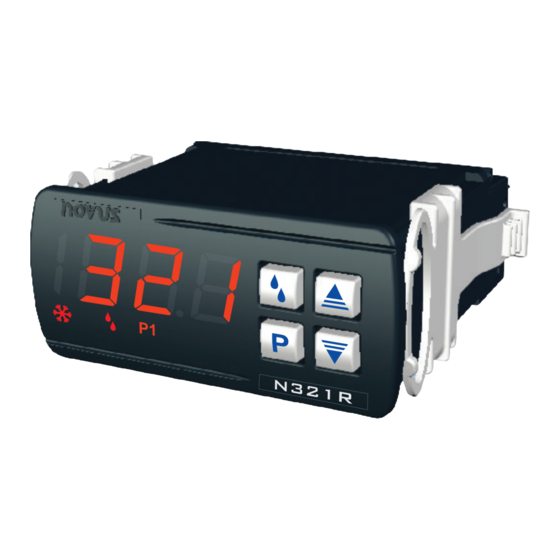
TEMPERATURE CONTROLLER
N321R
OPERATING MANUAL V1.9x A
N321R is an electronic controller for refrigeration and has features to facilitate the defrost
process. It has input for temperature sensors type Pt100 or NTC thermistor and can correct
indication errors (Offset). Each type of sensor has a specific temperature measurement
range. The controller has a relay-type control output with Common, NO and NC contacts.
The characteristics of each controller are identi f ied on the body of the device and accordi n g
to the purchase order.
SPECIFICATIONS
SENSOR INPUT: The sensor is chosen at the time of purchase and displayed on the top
side of the thermometer case. The options are:
Thermistor NTC: 10 kΩ @ 25 °C; Range: -50 to 120 °C (-58 to 248 °F); Accuracy: 0.6
•
°C (1.1 °F).
Maximum error in the interchangeabil i ty of original NTC sensors: 0.75 °C (1.35 °F). This
error can be eliminated through the Offset parameter of the equipment.
Note: For the NTC thermistor option, the sensor is included in the equipment. Its
operating range is limited to -30 to +105 °C (-222 to +221 °F). It has a 3 m long, 2 x
0.5 mm² cable, which can be extended up to 200 meters.
Pt100: Range: -50 to 300 °C (-58 to 572 °F); α= 0,00385; 3 wires; Accuracy: 0.7 °C (1.3
•
°F); according to IEC-751 standards.
Measurement Resolution:............................................................ 0.1° from -19.9 to 199.9°
............................................................................1 °C elsewhere
Note: The equipment keeps its precision all over the range, despi t e the lack of display
resolution in a part of the range does not allow its vi s uali z ation.
OUTPUT1: .......................... Relay SPDT; 1 HP 250 Vac / 1/3 HP 125 Vac (16 A Resistive)
POWER SUPPLY: Voltage ........................................................ 100 to 240 Vac/dc (± 10 %)
Optionally: ........................................................................... 12 to 30 Vdc
Mains frequency: ..................................................................... 50~60 Hz
Power consumption:........................................................................ 5 VA
Dimensions:
Width x Height x Depth: ................................................ 75 x 33 x 75 mm
Weight: ............................................................................................100 g
Panel cut-out: ........................................................................70 x 29 mm
Environment: Operating temperature: ............. 0 to 40 °C (32 to 104 °F)
Storage temperature: .................................... -20 to 60 °C (-4 to 140 °F)
Relative humi d ity: ............................................................ 20 to 85 % RH
Housing: Polycarbonate UL94 V-2
Protection: Housing IP42, Frontal panel IP65
Serial interface not isolated from input circuit.
Serial interface isolated from power supply circuit, except for the model with 24 V
Literature # 1739
ELECTRICAL WIRING
The figure below indicates the connection terminals for the sensor, power and
controller output and a connection example.
* The serial communication interface is optional.
Pt100 with 3-wire connection. For 2-wire connection, terminals 11 and 13 must be
interconnected. For proper cable resistance compensation, the conductors must al l
have the same electrical resistances (same cross section).
INSTALLATION RECOMMENDATIONS
Input signal conductors must run through the plant separately from the supply and
•
output conductors. If possible, in grounded conduits.
All electronic instruments must be powered by a clean mains supply, proper for
•
instrumentation.
It is recommended to use RC FILTERS (47 Ω and 100 nF, series combination) at
•
contractor coil s , solenoi d s, etc.
OPERATION
Before use, you must configure the control l er. To configure it, you must set values for
the parameters that determine how the equipment operates. These configuration
parameters are organized in groups or levels, called parameter levels:
LEVEL
0
1
2
3
When you turn on the controller, the display shows the version of the equipment for 1
second. This information is important for eventual consultations with the manufacturer.
Then, the controller starts presenting the temperature value measured by the sensor.
This is level 0 or the Temperature Measurement level.
To access level 1, press
key to go back to level 0.
Suitable wiring: Up to 4.0 mm².
To access level 2, press
Release the
supply.
parameter in that level. At the end of the level, the controller returns to the first level
(0). Use the
and
Notes:
1
2
Fig. 01 - Connections shown on controller label
FUNCTION
Temperature Measurement
Setpoint Adjustment / Voltage indication
Parameters Configuration
Calibration
key for 1 second until the
S P
message shows up. Press
key for 2 seconds until the
Unt
message shows up.
key to remain in this level. Press
key to advance to the next
keys to alter a parameter value.
The programming is saved by the controller when it switches from
one parameter to another, and only then is it considered val i d .
Even in the event of a power outage, the programming is saved
in permanent memory.
If the keys are not used for longer than 20 seconds, the control l e r
returns to the measuring level, finishing and saving the
programming done so far.
Level 1 – Setpoint Adjustment
This level displays the Setpoint (SP) parameter only. It sets the desired temperature
value for the system. The current SP value is shown alternately. To program the
desired value, use
the
and keys.
Screen indicating the measured electrical voltage. If the voltage is below 150 V,
U
it should indicate 0. When it exceeds 254 V, it should saturate and indicate 255
V.
Voltage
Function available only for N321R-NTC-LVD model.
SP
Adjustment of the control temperature
or working temperature.
adjustment is limited to the values programmed in S P L and S Pk (see below).
Setpoint
Level 2 – Configuration Level
Displays the sequence of parameters that must be set by the user. The parameters
are shown alternately wi t h their values. To program the desired val u e, use the
keys.
Temperature unit. It allows you to choose the display unit for the measured
temperature.
Unt
0 Temperature in Celsius degrees
Unit
1 Temperature in Fahrenheit degrees
Adjustment for temperature
indication. Allows you to make small
oF S
adjustments to the temperature display, seeking to correct measurement
Offset
errors that appear, for example, when replacing the NTC temperature sensor.
Setpoint lower limit. Minimum value that can be used to program the
SPL
Setpoint. Must be programmed with a lower value than the one
programmed in s p K .
SP Low Limit
Setpoint upper limit. Maximum value that can be used to program the
SPH
Setpoint. Must be programmed with a higher value than the one programmed
in s p K .
SP High Limit
HYs
Control hysteresis. Differential between the point of turning the control
output relay on and off. In degrees.
Hysteresis
Defines the minimum off time for control output. Once the control output is
oF T
turned off, it remains so for at least the time programmed in this parameter.
Typically used to increase the life of the compressor in a refrigeration system.
Off time
For heating applications, program zero. Value in seconds (0 to 999 seconds).
Defines the minimum on time for control output. Once the control output is
ont
turned on, it remains so for at least the time programmed in this parameter.
Typically used to increase the life of the compressor in a refrigeration system.
On time
For heating applications, program zero. Value in seconds (0 to 999 seconds).
Delay time for control start. After the controller is switched on, the control
output will only be switched on when the time programmed in this
dL y
parameter has elapsed. Used in large refrigeration systems to prevent
Delay
simultaneous compressor starts on return from a power failure. Value in
seconds (0 to 250 seconds).
Time base for d f i:
dIb
0 Seconds
Defrost
1 Minutes
Interval Base
2 Hours
Time base for d f t :
dt b
0 Seconds
Defrost Time
1 Minutes
Base
2 Hours
This
and
Advertisement

Related Manuals for Novus N321R


Summary of Contents for Novus N321R
- Page 1 Screen indicating the measured electrical voltage. If the voltage is below 150 V, it should indicate 0. When it exceeds 254 V, it should saturate and indicate 255 N321R is an electronic controller for refrigeration and has features to facilitate the defrost Voltage process.
- Page 2 Enable compressor protection. is active. The defrost process of this controller is executed by stopping the compressor. Function available only for N321R-NTC-LVD model. ERROR MESSAGES This procedure is done every ti m e interval defined by the user. The control output remai n s...
Need help?
Do you have a question about the N321R and is the answer not in the manual?
Questions and answers