Vacon 10 Complete User's Manual
Hide thumbs
Also See for 10:
- Complete user's manual (102 pages) ,
- Quick manual (38 pages) ,
- User instruction (8 pages)
Table of Contents
Advertisement
Advertisement
Table of Contents

Related Manuals for Vacon 10


Summary of Contents for Vacon 10
-
Page 2: Table Of Contents
3.2.5 Stripping lengths of motor and mains cables 3.2.6 Cable installation and the UL standards 3.2.7 Cable and motor insulation checks 4. Commissioning 4.1 Commissioning steps of Vacon 10 5. Fault tracing 6. Vacon 10 Application Interface 6.1 Introduction 6.2 Control I/O... - Page 3 9.8 Motor thermal protection (parameters 9.7 - 9.10) 9.9 Fault autoreset parameters (Panel: Menu PAR -> P10) 9.10 PI control parameters (Control panel: Menu PAR -> P12) 9.11 Easy usage menu (Control panel: Menu PAR -> P9) 9.11.1 Termination resistor 9.11.2 Modbus address area...
- Page 4 10.1 Vacon 10 technical data 10.2 Power ratings 10.2.1 Vacon 10 - Mains voltage 115 V 10.2.2 Vacon 10 - Mains voltage 208 - 240 V 10.2.3 Vacon 10 - Mains voltage 380 - 480 V 10.2.4 Vacon 10 - Mains voltage 575 V...
-
Page 5: Safety
1.1 Warnings The components of the power unit of the frequency converter are live when Vacon 10 is connected to mains. Coming into contact with this voltage is extremely dangerous and may cause death or severe injury. The control unit is isolated from the mains potential. - Page 6 After disconnecting the frequency converter from the mains, wait until the fan stops and the indicators on the display go out. Wait 5 more minutes before doing any work on Vacon 10 connections. The motor can start automatically after a fault situation, if the autoreset function has been activated Tel.
-
Page 7: Safety Instructions
Do not open the cover of Vacon 10. Static voltage discharge from your fingers may damage the components. Opening the cover may also damage the device. If the cover of Vacon 10 is opened, warranty becomes void. 1.3 Earthing and earth fault protection The Vacon 10 frequency converter must always be earthed with an earthing conduc- tor connected to the earthing terminal. -
Page 8: Before Running The Motor
• vacon safety 1.4 Before running the motor Checklist: Before starting the motor, check that the motor is mounted properly and ensure that the machine connected to the motor allows the motor to be started. Set the maximum motor speed (frequency) according to the motor and the machine connected to it. -
Page 9: Receipt Of Delivery
If the delivery does not correspond to your order, contact the supplier immediately. Type designation code Vacon 0010 - 1L - 0001 - 4 Machinery +SMO1 +EMC2 Changes to default setup: +SM01 = AP I RS-485 -> API Full +E MC2 = EMC C4 ->... -
Page 10: Warranty
The local distributor may grant a warranty time different from the above. This war- ranty time shall be specified in the distributor's sales and warranty terms. Vacon as- sumes no responsibility for any other warranties than that granted by Vacon itself. -
Page 11: Manufacturer's Declaration Of Conformity
Vacon 10 Frequency Converter Product name: Model designation: Vacon 10 1L 0001 1…to 1L 0005 1 Vacon 10 1L 0001 2…to 1L 0009 2 Vacon 10 3L 0001 2…to 3L 0011 2 Vacon 10 3L 0001 4...to 3L 0012 4 Vacon 10 3L 0002 6…to 1L 0011 6... -
Page 12: Installation
3. INSTALLATION 3.1 Mechanical installation There are two possible ways to mount Vacon 10 in the wall; either screw or DIN-rail mounting. The mounting dimensions are given on the back of the drive and on the fol- lowing page. -
Page 13: Vacon 10 Dimensions
• installation vacon 3.1.1 Vacon 10 dimensions Figure 3.4: Vacon 10 dimensions, MI1-MI3 Type 160.1 137,3 65,5 37,8 98,5 62,5 101,5 254,3 229,3 108,5 Table 3.1: Vacon 10 dimensions in millimetres 24-hour support (0)201 212 575 • Email: vacon@vacon.com... -
Page 14: Cooling
Table 3.3: Required cooling air NOTE! See the mounting dimensions on the back of the drive. Leave free space for cooling above (100 mm), below (50 mm), and on the sides (10 mm) of Vacon 10! (Side-to-side installation allowed only if the ambient temperature is below 40°C). -
Page 15: Changing The Emc Protection Class From C2 Or C3 To C4 For It Networks
3.1.4 Changing the EMC protection class from C2 or C3 to C4 for IT net- works The EMC protection class of Vacon 10 frequency converters can be changed from class C2 or C3 to class C4 for IT networks by removing the EMC-capacitor discon- necting screw, see figure below. -
Page 16: Cabling And Connections
Motor out L1 L2/N L3 R+ R- U/T1 V/T2 W/T3 Strip the plastic cable coating for 360° earthing BRAKE MOTOR MAINS RESISTOR Figure 3.6: Vacon 10 power connections, MI2 - MI3 Tel. +358 (0)201 2121 • Fax +358 (0)201 212205... -
Page 17: Control Cabling
• installation vacon 3.2.2 Control cabling Attach the support AFTER installing the power cables Attach this plate BEFORE installing the power cables Figure 3.7: Mount the PE- plate and API cable support 24-hour support (0)201 212 575 • Email: vacon@vacon.com... - Page 18 • vacon installation Figure 3.8: Open the lid Control cable tightening torque: 0.4 Nm Strip the plastic cable coating for 360°earthing Figure 3.9: Install the control cables. See Chapter 6.3 Tel. +358 (0)201 2121 • Fax +358 (0)201 212205...
-
Page 19: Cable And Fuse Specifications
(NKCABLES /MCCMK, SAB/ÖZCUY-J or similar recommended). *360º earthing of both motor and FC connection required to meet the standard Screened cable equipped with compact low-impedance shield (NKCABLES /Jamak, SAB/ÖZCuY-O or similar). Table 3.5: Cable type descriptions 24-hour support (0)201 212 575 • Email: vacon@vacon.com... - Page 20 1.5-4 1.5-4 0.5-1.5 0.5-1.5 0011 3*2.5+2.5 3*2.5+2.5 1.5-6 1.5-6 0.5-1.5 0.5-1.5 Table 3.7: Cable and fuse sizes for Vacon 10, 208 - 240V, 1~ and 3~ Terminal cable size (min/max) Mains Motor Fuse cable cable Frame Type Main Earth Control...
- Page 21 1.5-6 1.5-6 0.5-1.5 0.5-1.5 Table 3.9: Cable and fuse sizes for Vacon 10, 575V Note! To fulfil standard EN61800-5-1, the protective conductor should be at least 10mm Cu or 16mm Al. Another possibility is to use an additional protective con- ductor of at least the same size as the original one.
-
Page 22: General Cabling Rules
If cable insulation checks are needed, see Chapter 3.2.7. Connecting the cables: • Strip the motor and mains cables as advised in Figure 3.10. • Connect the mains, motor and control cables into their respective terminals, see Figures 3.5 - 3.9. -
Page 23: Stripping Lengths Of Motor And Mains Cables
Measure the insulation resistance of each motor winding. The measurement voltage must equal at least the motor nominal voltage but not exceed 1000 V. The insulation resistance must be >1MOhm. 24-hour support (0)201 212 575 • Email: vacon@vacon.com... -
Page 24: Commissioning
4. COMMISSIONING Before commissioning, note the warnings and instructions listed in Chapter 1! 4.1 Commissioning steps of Vacon 10 Read carefully the safety instructions in Chapter 1 and follow them. After the installation, make sure that: • both the frequency converter and the motor are grounded •... - Page 25 Connect the motor to the process (if the no-load test was run without the motor being connected) • Before running the tests, make sure that this can be done safely. • Inform your co-workers of the tests. • Repeat test 7A or 7B. 24-hour support (0)201 212 575 • Email: vacon@vacon.com...
-
Page 26: Fault Tracing
• high overvoltage spikes in mains Current measurement has detected extra leakage current at Check motor cables and Earth fault start: motor • insulation failure in cables or motor Table 5.10: Fault codes Tel. +358 (0)201 2121 • Fax +358 (0)201 212205... - Page 27 Motor underload protection has Check motor and load, Motor underload tripped e.g. for broken belts or dry pumps Table 5.10: Fault codes 24-hour support +358 (0)40 837 1150 • Email: vacon@vacon.com...
- Page 28 Run command was removed before comple- tion of identification run. Idenfication fault Identification run has failed. Motor is not connected to frequency converter. There is load on motor shaft Table 5.10: Fault codes Tel. +358 (0)201 2121 • Fax +358 (0)201 212205...
-
Page 29: Vacon 10 Application Interface
• vacon 10 api vacon 6. VACON 10 APPLICATION INTERFACE 6.1 Introduction There are three versions of Application Interfaces (API) available for the Vacon 10 drive: API RS-485 (Modbus API Full API Limited RTU) 6 Digital inputs 3 Digital inputs... - Page 30 • vacon vacon 10 api • Current signal input fault • External fault • Undervoltage fault • Earth fault • Motor thermal, stall and underload protection • Fieldbus communication Special features in API Full and API Limited: • 8 preset speeds •...
-
Page 31: Control I/O
25 RO 21 0,4A 26 RO 24 Table 6.2: Vacon 10 General purpose application default I/O configuration and connections for API FULL version P) = Programmable function, see parameter lists and descriptions, chapters 8 and 24-hour support +358 (0)40 837 1150 • Email: vacon@vacon.com... - Page 32 250Vac/2A or 250Vdc/ opened) = FAULT 25 RO 21 0,4A Table 6.3: Vacon 10 General purpose application default I/O configuration and connections for API LIMITED version P) = Programmable function, parameter lists and descriptions, chapters 8 and 9. API RS-485...
-
Page 33: Control Panel
7. CONTROL PANEL 7.1 General The Vacon 10 API Full and API Limited versions have similar control panels. The panel is integrated to the drive consisting of corresponding application card and an overlay on the drive cover with status display and button clarifications. -
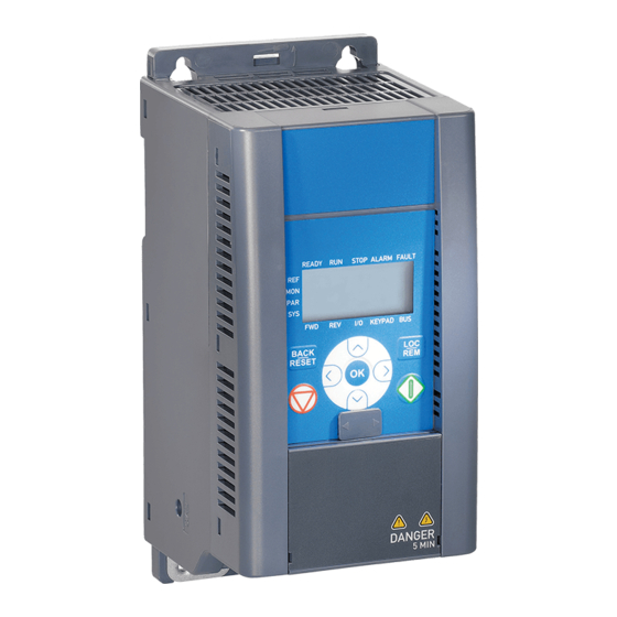
Page 34: Keypad
Start Stop button button Figure 7.11: Vacon 10 Control panel 7.3 Keypad The keypad section of the control panel consists of a navigation wheel and START and STOP buttons (see Figure 7.11). The navigation wheel is used for navigating on the panel display, but it also works as a reference potentiometer when KEYPAD has been selected as the control place of the drive. -
Page 35: Navigation On The Vacon 10 Control Panel
7.4 Navigation on the Vacon 10 control panel This chapter provides you with information on navigating the menus on Vacon 10 and editing the values of the parameters. 7.4.1 Main menu The menu structure of Vacon 10 control software consists of a main menu and several submenus. -
Page 36: Reference Menu
• vacon control panel 7.4.2 Reference menu READY RUN STOP ALARM FAULT I/O KEYPAD Push to enter Change Push to edit mode value confirm Figure 7.13: Reference menu display Move to the reference menu with the navigation wheel (see Figure 7.12). The refe- rence value can be changed with the navigation wheel as shown in Figure 7.13. -
Page 37: Monitoring Menu
Pushing the navigation wheel once in this menu takes the user to the next level, where the monitoring value, e.g. M1.11 and value are visible (see Figure 7.12). The monitoring values can be browsed by rolling the navigation wheel clockwise, as shown in Figure 7.14. 24-hour support +358 (0)40 837 1150 • Email: vacon@vacon.com... - Page 38 PI feedback actual value In percent of the maximum error M1.19 PI error value value In percent of the maximum out- M1.20 PI Output put value Table 7.15: Vacon 10 monitoring signals Tel. +358 (0)201 2121 • Fax +358 (0)201 212205...
-
Page 39: Parameter Menu
The following figure shows the parameter menu view: Alternates in the display READY RUN STOP ALARM FAULT KEYPAD Browse Push to enter Change Push to P1.1 -> edit mode value confirm Figure 7.15: Parameter menu 24-hour support +358 (0)40 837 1150 • Email: vacon@vacon.com... -
Page 40: Fault History Menu
• vacon control panel 7.4.5 Fault history menu READY RUN STOP ALARM FAULT READY RUN STOP ALARM FAULT Push I/O KEYPAD I/O KEYPAD Browse faults 1-9 READY RUN STOP ALARM FAULT READY RUN STOP ALARM FAULT Push I/O KEYPAD I/O KEYPAD... -
Page 41: Standard Application Parameters
More information on this parameter available in chapter 9: ‘Param- eter descriptions’ click on the parameter name. NOTE: This manual is for Vacon 10 standard application only. If you are using a spe- cial application, please download the appropriate user manual on http://www.va- con.com ->... -
Page 42: Quick Setup Parameters (Virtual Menu, Shows When Par. 13.1 = 1)
Activated by digital P3.4 Preset speed 0 0,00 P3.2 5,00 inputs Activated by digital P3.5 Preset speed 1 0,00 P3.2 10,00 inputs Activated by digital P3.6 Preset speed 2 0,00 P3.2 15,00 inputs Activated by digital P3.7 Preset speed 3 0,00 P3.2... - Page 43 Fault autoreset 0 = Not used 1 = Used 0 = All parameters visi- Parameter P13.1 1 = Only quick setup conceal parameter group vis- ible Table 8.1: Quick setup parameters 24-hour support +358 (0)40 837 1150 • Email: vacon@vacon.com...
-
Page 44: Motor Settings (Control Panel: Menu Par -> P1)
0 = Frequency control P1.8 mode 1 = Speed control 0 = Linear P1.9 U/f ratio selection 1 = Squared 2 = Programmable Field weakening P1.10 50,00 30,00 point Voltage at field % of Nominal voltage of the P1.11 100,00 10,00 weakening point... -
Page 45: Start/Stop Setup (Control Panel: Menu Par -> P2)
40,00 129 Activated by digital inputs P3.11 Preset speed 7 0,00 P3.2 50,00 130 Activated by digital inputs Table 8.4: Frequency references NOTE! These parameters are shown, when P13.1 = 0. 24-hour support +358 (0)40 837 1150 • Email: vacon@vacon.com... -
Page 46: Ramps And Brakes Setup (Control Panel: Menu Par -> P4)
8.5 Ramps and brakes setup (Control panel: Menu PAR -> P4) Code Parameter Unit Default Note 0 = Linear P4.1 Ramp shape 10,0 >0 = S-curve ramp time P4.2 Acceleration time 3000 P4.3 Deceleration time 3000 0.2 x P4.4... -
Page 47: Analogue Inputs (Control Panel: Menu Par -> P6)
389 0 = no filtering P6.7 AI2 Custom min 100,0 391 0,0 = no min scaling -100,0 P6.8 AI2 Custom max 100,0 100,0 392 100,0 = no max scaling -100,0 Table 8.7: Analoque inputs 24-hour support +358 (0)40 837 1150 • Email: vacon@vacon.com... -
Page 48: Digital And Analogue Outputs (Panel: Menu Par -> P7)
P7.1 6 = Reversed content 7 = At Speed 8 = Motor Regulator Active 9 = FBControlWord.B13 10 = FBControlWord.B14 11 = FBControlWord.B15 In all API versions Relay output 2 P7.2 314 As parameter 7.1 content Only in API FULL Digital output 1 P7.3... -
Page 49: Protections (Control Panel: Menu Par -> P9)
P9.9 150,0 40,0 tor at zero speed Motor thermal P9.10 time constant Motor Phase P9.11 unit 702 Description Supervision Table 8.9: Protections NOTE! These parameters are shown, when P13.1 = 0. 24-hour support +358 (0)40 837 1150 • Email: vacon@vacon.com... -
Page 50: Fault Autoreset Parameters (Panel: Menu Par -> P10)
• vacon parameters 8.10 Fault autoreset parameters (Control panel: Menu PAR -> P10 ) Code Parameter Unit Default ID Note Delay before automatic P10.1 Wait time 0,10 10,00 0,50 restart after a fault has dis- appeared 90,00 Defines the time before the (FULL &... -
Page 51: Pi Control Parameters (Control Panel: Menu Par -> P12)
100,0 100,0 0=No inversion (Feed- back<Setpoint->Increase PI Error value P12.9 Output) inversion 1=Inverted (Feedback<Set- point->Decrease PI Output) Table 8.11: PI control parameters NOTE! These parameters are shown, when P13.1 = 0. 24-hour support +358 (0)40 837 1150 • Email: vacon@vacon.com... -
Page 52: Easy Usage Menu (Control Panel: Menu Par -> P0)
• vacon parameters 8.12 Easy usage menu (Control panel: Menu PAR -> P0) Code Parameter Unit Default Note 0 = All parameters visible Parameter 1 = Only quick setup P13.1 conceal parameter group visi- 0 = Basic 1 = Pump drive 2 = Fan drive P13.2... - Page 53 (1.1. - 1.20) is shown S4.2 Default page 2318 after startup. 0 = Not used 1= Restores factory defaults S4.3 Restore factory defaults for all parameters Table 8.13: System parameters 24-hour support +358 (0)40 837 1150 • Email: vacon@vacon.com...
-
Page 54: Parameter Descriptions
• vacon parameter descriptions 9. PARAMETER DESCRIPTIONS On the next pages you can find the descriptions of certain parameters. The descrip- tions have been arranged according to parameter group and number. 9.1 Motor settings (Control panel: Menu PAR -> P1) - Page 55 2 = Programmable U/f curve: The U/f curve can be programmed with three different points. Pro- grammable U/f curve can be used if the other settings do not satisfy the needs of the application 24-hour support +358 (0) 201 212 575 • Email: vacon@vacon.com...
- Page 56 Par. 1.13 (Def. 50%) Default: Nominal frequency of the Par. 1.14 motor f[Hz] (Def. 0.0%) Par. 1.12 Par. 1.10 (Def. 10%) Figure 9.2: Programmable U/f curve Tel. +358 (0)201 2121 • Fax +358 (0)201 212205...
- Page 57 See parameters 1.9 - 1.14 and Figures 9.1 and 9.2. When the parameters 1.1 and 1.2 (nominal voltage and nominal frequency of the motor) are set, the parameters 1.10 and 1.11 are automatically given the corresponding values. If you need different values for the field weakening point and the voltage, change these parameters after setting the parameters 1.1 and 1.2.
- Page 58 WITCHING FREQUENCY Motor noise can be minimised using a high switching frequency. Increasing the switching frequency reduces the capacity of the frequency converter unit. Switching frequency for Vacon 10: 1.5…16 kHz. 1.17 B RAKE CHOPPER Note! An internal brake chopper is installed in three phase supply MI2 and MI3...
-
Page 59: Start/Stop Setup (Control Panel: Menu Par -> P2)
Local = Keypad is the control place Remote = P2.1 defines the control place TART FUNCTION The user can select two start functions for Vacon 10 with this parameter: 0 = Ramp start The frequency converter starts from 0 Hz and accelerates to the set frequency reference within the set acceleration time (See detailed de- scription: ID103). - Page 60 • vacon parameter descriptions TOP FUNCTION Two stop functions can be selected in this application: 0 = Coasting The motor coasts to a halt without control from the frequency convert- er after the Stop command. 1 = Ramp stop After the Stop command, the speed of the motor is decelerated ac- cording to the set deceleration parameters.
- Page 61 Start Stop Figure 9.5: Start/Stop logic, selection 2 3 = DI1 = Start forward, rising edge after fault DI2 = Start reverse, rising edge after fault (API FULL & LIMITED) 24-hour support +358 (0) 201 212 575 • Email: vacon@vacon.com...
- Page 62 • vacon parameter descriptions OCAL REMOTE This parameter defines whether the control place of the drive is remote (I/O or FieldBus) or Keypad. Keypad can also be selected as control place by pressing the navigation wheel for 5 seconds. The priority order of selecting control place is 1.
-
Page 63: Frequency References (Control Panel: Menu Par -> P3)
Preset speed 0 Preset speed 1 Preset speed 2 Preset speed 3 Preset speed 4 Preset speed 5 Preset speed 6 Preset speed 7 Table 9.1: Preset speeds 0 - 7 24-hour support +358 (0) 201 212 575 • Email: vacon@vacon.com... -
Page 64: Ramps & Brakes Setup (Control Panel: Menu Par -> P4)
Setting value 0 gives a linear ramp shape which causes acceleration and deceleration to act immediately to the changes in the refer- ence signal. Setting value 0.1…10 seconds for this parameter produces an S-shaped accel- eration/deceleration. The acceleration and deceleration times are determined with parameters 4.2 and 4.3. - Page 65 DC-braking. After the brake is released, the output fre- quency increases according to the set start function by par. 2.2. Output DC-braking frequency current Par 4.4 Par 4.5 STOP Figure 9.7: DC braking time at start 24-hour support +358 (0) 201 212 575 • Email: vacon@vacon.com...
- Page 66 4.7 determines the braking time. For example, when the frequency is 10% of the nominal, the braking time is 10% of the set value of parameter 4.7.
- Page 67 Note: Flux braking converts the energy into heat at the motor, and should be used intermittently to avoid motor damage. 24-hour support +358 (0) 201 212 575 • Email: vacon@vacon.com...
-
Page 68: Digital Inputs (Control Panel: Menu Par -> P5)
CLOSE XTERNAL FAULT OPEN AULT RESET UN ENABLE RESET SPEED RESET SPEED 5.10 P RESET SPEED 5.11 D ISABLE 5.12 F ORCE TO The control place is forced to I/O by activating the digital input that this func- tion is programmed to. -
Page 69: Analoque Inputs (Control Panel: Menu Par -> P6)
ONLY IN API FULL This parameter, given a value greater than 0, activates the function that filters out disturbances from the incoming analogue signal. Long filtering time makes the regulation response slower. See Figure 9.10. Unfiltered signal 100% Filtered signal t [s] Par. -
Page 70: Digital And Analoque Outputs (Panel: Menu Par -> P7)
One of the limit regulators (e.g. current vated limit, voltage limit) is activated 9 = FBControlWord.B13 Modbus control word bit 13 10 = FBControlWord.B14 Modbus control word bit 14 11 = FBControlWord.B15 Modbus control word bit 15 Table 9.2: Output signals via RO1, RO2 and DO1... -
Page 71: Motor Thermal Protection (Parameters 9.7 - 9.10)
There is actually no real indication of the shaft rotation. Stall area Inmotor *1.3 25Hz Figure 9.11: Stall characteristics 24-hour support +358 (0) 201 212 575 • Email: vacon@vacon.com... - Page 72 Torque Underload curve at nominal freq. = 50% Underload curve at zero freq. = 10% Underload area 5 Hz Field weakening point, P1.11 Figure 9.12: Underload protection...
- Page 73 When the motor ambient temperature must be taken into consideration, it is recommended to set a value for this parameter. The value can be set between -20 and 100 degrees Celsius. 24-hour support +358 (0) 201 212 575 • Email: vacon@vacon.com...
- Page 74 Overload area 100% par.9.9=40% Figure 9.13: Motor cooling power 9.10 M OTOR THERMAL TIME CONSTANT This time can be set between 1 and 200 minutes. This is the thermal time constant of the motor. The bigger the motor, the big- ger the time constant.
- Page 75 Motor phase supervision of the motor ensures that the motor phases have an approximately equalcurrent. Settings for P9.11, range 0-2: Activation mode Description No response Warning Fault,stop mode after fault according to ID506(P2.3 Stop func- tion) 24-hour support +358 (0) 201 212 575 • Email: vacon@vacon.com...
-
Page 76: Fault Autoreset Parameters (Panel: Menu Par -> P10)
• vacon parameter descriptions 9.9 Fault autoreset parameters (Control panel: Menu PAR -> P10) 10.2 A UTO RESET TRIAL TIME The Automatic restart function restarts the frequency converter when the faults have disappeared and the waiting time has elapsed. The time count starts from the first autoreset. If the number of faults occur- ring during the trial time exceeds three, the fault state becomes active. -
Page 77: Pi Control Parameters (Control Panel: Menu Par -> P12)
CONTROLLER GAIN This parameter defines the gain of the PI controller. If the value of the param- eter is set to 100% a change of 10% in the error value causes the controller output to change by 10%. 12.3 PI... -
Page 78: Easy Usage Menu (Control Panel: Menu Par -> P9)
• vacon parameter descriptions 9.11 Easy usage menu (Control panel: Menu PAR -> P9) 13.2 D RIVE SETUP With this parameter you can easily set up your drive for four different applica- tions. Note! This parameter is only visible when the Startup Wizard is active. The startup wizard will start in first power-up. - Page 79 P3.3 I/O reference P2.1 Control place P4.2 Acc. time (s) P2.2 Start function P4.3 Dec time (s) READY RUN STOP ALARM FAULT Push to confirm drive setup Figure 9.18: Drive setup 24-hour support +358 (0) 201 212 575 • Email: vacon@vacon.com...
-
Page 80: Termination Resistor
9.12 Modbus RTU Vacon 10 has a built-in Modbus RTU bus interface. The signal level of the interface is in accordance with the RS-485 standard. The built-in Modbus connection of Vacon 10 supports the following function codes:... -
Page 81: Modbus Process Data
32004, 42004 PI Control Reference 0,01 2005 32005, 42005 PI Actual value 0,01 2006 32006, 42006 2007 32007, 42007 2008 32008, 42008 2009 32009, 42009 2010 32010, 42010 2011 32011, 42011 24-hour support +358 (0) 201 212 575 • Email: vacon@vacon.com... - Page 82 • vacon parameter descriptions Status word (output process data) Information about the status of the device and messages is indicated in the Status word. The Status word is composed of 16 bits the meanings of which are described in the table below:...
-
Page 83: Technical Data
> 120% Connection to mains Once per minute or less (normal case) Supply network Networks Vacon 10 (400V) cannot be used with corner grounded net- works Short circuit current Maximum short circuit current has to be < 50kA Motor Output voltage... - Page 84 • vacon technical data Ambient Ambient operating tem- -10°C (no frost)…+40/50°C (depends on the unit size): perature rated loadability I conditions Storage temperature -40°C…+70°C Relative humidity 0…95% RH, non-condensing, non-corrosive, no dripping water Air quality: - chemical vapours IEC 721-3-3, unit in operation, class 3C2 - mech.
-
Page 85: Power Ratings
0002 0,37 0,55 0003 0,55 0,55 0004 0,75 0,70 0005 11,2 0,70 0007 10,5 14,1 0,70 0009 14,4 22,1 0,99 Table 10.3: Vacon 10 power ratings, 208 - 240 V, 1~ 24-hour support +358 (0)40 837 1150 • Email: vacon@vacon.com... -
Page 86: Vacon 10 - Mains Voltage 380 - 480 V
10,5 0,70 0011 16,5 13,4 0,99 Table 10.4: Vacon 10 power ratings, 208 - 240 V, 3~ 10.2.3 Vacon 10 - Mains voltage 380 - 480 V Mains voltage 380-480 V, 50/60 Hz, 3~ series Rated loadability Motor shaft Nominal... -
Page 87: Vacon 10 - Mains Voltage 575 V
Contact the manufacturer for data! Note! Only 3-phase MI2 and MI3 drives are equipped with brake chopper. For further information on brake resistors, please download Vacon NX Brake Resis- tor Manual (UD00971C) on http://www.vacon.com/Support & Downloads 24-hour support +358 (0)40 837 1150 • Email: vacon@vacon.com...
Need help?
Do you have a question about the 10 and is the answer not in the manual?
Questions and answers