Vacon 10 Quick Manual
Hide thumbs
Also See for 10:
- Complete user's manual (102 pages) ,
- Quick manual (38 pages) ,
- User instruction (8 pages)
Advertisement
Quick Links
Advertisement

Related Manuals for Vacon 10


Summary of Contents for Vacon 10
- Page 2 After disconnecting the frequency converter from the mains, wait until the fan stops and the indicators on the display go out. Wait 5 more minutes before doing any work on Vacon 10 connections. The motor can start automatically after a fault situation, if autorestart function has been activated.
- Page 3 NOTE! See the mounting dimensions on the back of the drive. Leave free space for cooling above (4 in) and below (2 in) Vacon 10,and on the sides (4 in) of Vacon 10! (Side-to-side installation allowed only if the ambient temperature is below 104F).
- Page 4 L1 L2/N L3 R+ R- U/T1 V/T2 W/T3 Strip the plastic cable coating for 360° earthing BRAKE MOTOR MAINS RESISTOR Figure 4: Vacon 10 power connections, MI2 - MI3 Tel. +1 877 822 6606 • Fax +1 717 264 3115...
- Page 5 2.2.2 Control cabling Figure 5: Open the cover Control cable tightening torque: 3 in-lbs Strip the plastic cable coating for 360°earthing Figure 6: Install the control cables. See next page! 24-hour support +1 877 822 6606 • Email: usa@vacon.com...
- Page 6 Description +10Vref Ref. voltage out Maximum load 10 mA Ω Analog signal in 1 Freq. reference 0 - +10 V Ri = 200 k (min) I/O signal ground ± 24Vout 24V output for DI's %, max. load 50 mA I/O signal ground...
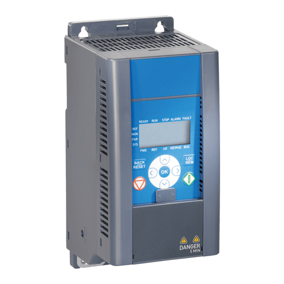
- Page 7 PUSH faults occurred. I/O KEYPAD I/O KEYPAD Figure 7: The main menu of Vacon 10 Note! You can quickly change the active control place from remote to local and back by pressing the navigation wheel for a few seconds! 24-hour support +1 877 822 6606 • Email: usa@vacon.com...
- Page 8 Table 2: Commissioning steps 4.4.2 Startup wizard Vacon 10 runs the startup wizard in first power-up. After that the wizard can be run by pressing STOP for 5 seconds in main menu. The following figures show the pro- cedure.
- Page 9 P3.3 I/O reference P2.1 Control place P4.2 Acc. time (s) P2.2 Start function P4.3 Dec time (s) READY RUN STOP ALARM FAULT MO N Push to confirm drive setup Figure 9: Drive setup 24-hour support +1 877 822 6606 • Email: usa@vacon.com...
- Page 10 • vacon monitoring & parameters 5. MONITORING & PARAMETERS NOTE! Complete parameter listing and descriptions are given in Vacon 10 User Manual on: www.vacon.com -> Support & downloads. 5.1 Monitoring values Code Monitoring signal Unit Description M1.1 Output frequency Frequency to the motor M1.2...
- Page 11 Activated by digital inputs P3.7 Preset speed 3 0,00 P3.2 20,00 Activated by digital inputs Acceleration time from 0 P4.2 Acceleration time 3000 Hz to maximum frequency Table 4: Quick setup parameters 24-hour support +1 877 822 6606 • Email: usa@vacon.com...
- Page 12 Deceleration time from P4.3 Deceleration time 3000 maximum frequency to 0 API FULL and LIMITED: 0 = Voltage 0…10 V 1 = Voltage 2…10 V API LIMITED ONLY: 2 = Current 0…20 mA P6.1 AI1 Signal range 3 = Current 4…20 mA...
- Page 13 1=Used in Run state P1.17 Brake chopper 2=Used in Run and Stop state Only in API FULL & LIMITED 1=Identification without P1.18 Motor identification run after start command Table 5: Motor settings 24-hour support +1 877 822 6606 • Email: usa@vacon.com...
- Page 14 P3.4 Preset speed 0 0,00 P3.2 5,00 124 Activated by digital inputs P3.5 Preset speed 1 0,00 P3.2 10,00 105 Activated by digital inputs P3.6 Preset speed 2 0,00 P3.2 15,00 106 Activated by digital inputs P3.7 Preset speed 3 0,00 P3.2...
- Page 15 Flux braking cur- P4.9 rent 0 = Linear P4.10 Ramp shape 2 10,0 >0 = S-curve ramp time Acceleration time P4.11 3000 Deceleration time P4.12 3000 Table 8: Ramps and brakes setup 24-hour support +1 877 822 6606 • Email: usa@vacon.com...
- Page 16 Run enable 407 As parameter 5.1 P5.8 Preset speed B0 419 As parameter 5.1 P5.9 Preset speed B1 420 As parameter 5.1 P5.10 Preset speed B2 421 As parameter 5.1 P5.11 Disable PI 1020 As parameter 5.1 P5.12 Force to I/O 409 As parameter 5.1...
- Page 17 391 0,0 = no min scaling -100,0 P6.8 AI2 Custom max -100,0 100,0 100,0 392 100,0 = no max scaling Table 10: Analogue inputs NOTE! These parameters are shown, when P13.1 = 0. 24-hour support +1 877 822 6606 • Email: usa@vacon.com...
- Page 18 P7.1 P7.6 content 6 = Reversed 7 = At Speed 8 = Motor Regulator Active 9 = FBControlWord.Bit13 10 = FBControlWord.Bit14 11 = FBControlWord.Bit15 In all API versions Relay output 2 P7.2 314 As parameter 7.1 content Only in API FULL Digital output 1 P7.3...
- Page 19 • monitoring & parameters vacon 5.10 Protections (Control panel: Menu PAR -> P9) Code Parameter Unit Default Note 0 = No response Response to 4mA 1 = Alarm P9.1 reference fault 2 = Fault, stop acc. to P2.3 Response to 1 = Alarm P9.2...
- Page 20 5.11 Fault autoreset parameters (Control panel: Menu PAR -> P10) Code Parameter Unit Default Note Delay before automatic P10.1 Wait time 0,10 10,00 0,50 restart after a fault has dis- appeared 90,00 Defines the time before the (FULL & frequency converter tries to LIMITED) P10.2...
- Page 21 2 = Fan drive P13.2 Drive setup 3 = Conveyor drive (HP) NOTE! Visible only during Startup wizard Table 15: Easy usage menu NOTE! These parameters are shown, when P13.1 = 0. 24-hour support +1 877 822 6606 • Email: usa@vacon.com...
- Page 22 • vacon monitoring & parameters 5.14 System menu parameters Code Parameter Max Default Note Software information (MENU PAR -> S1) S1.1 API system SW 2314 S1.2 API system SW version S1.3 Power SW ID 2315 S1.4 Power SW version S1.5 Application SW ID S1.6...
- Page 23 IGBT Overtemperature Analogue input I < 4mA (selected signal range 4 to 20 mA) External fault Fieldbus fault Identification fault Table 1: Fault codes. See User Manual for detailed fault descriptions. 24-hour support +1 877 822 6606 • Email: usa@vacon.com...
- Page 24 0,55 101,5 0,70 254,3 108,5 0,99 Supply network Networks Vacon 10 (400V) cannot be used with corner grounded networks Short circuit current Maximum short circuit current has to be < 50kA Motor Output voltage 0 - U connection Output current Continuous rated current I at ambient temperature max.
- Page 25 100% contin. 150% overload [ A ] current I [ A ] current [ A ] [ HP ] 0001 0.33 0002 11,6 0003 0.75 12,4 0004 0005 16,5 24-hour support +1 877 822 6606 • Email: usa@vacon.com...
- Page 26 [ A ] current I [ A ] current [ A ] [ kW ] 0001 0,25 0002 0,37 0003 0,55 0004 0,75 0005 11,2 0007 10,5 14,1 0009 14,4 22,1 Tel. +1 877 822 6606 • Fax +1 717 264 3115...
- Page 27 Vacon 10-3L-0004-4 Vacon 10-3L-0005-4 Vacon 10-3L-0006-4 Vacon 10-3L-0008-4 11,4 Vacon 10-3L-0009-4 13,5 11,5 Vacon 10-3L-0012-4 12,0 18,0 14,9 Note: The input currents are calculated values with 100 kVA line transformer supply. 24-hour support +1 877 822 6606 • Email: usa@vacon.com...
- Page 28 [ HP ] 0002 0003 0004 0006 0009 13,5 10,4 0011 16,5 14,1 Note: The input currents are calculated values with 100 kVA line transformer supply. Quick Modbus setup A: Select Fieldbus as remote control place: P2.1 to 3 – Fieldbus B: Set Modbus RTU protocol to “ON”: S2.2 to 1 –...
Need help?
Do you have a question about the 10 and is the answer not in the manual?
Questions and answers