Table of Contents
Advertisement
Quick Links
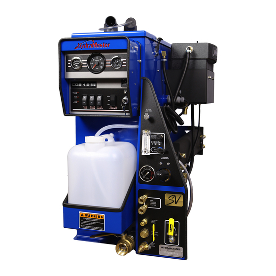
Clutch Drive System 4.8
Owner's Manual
HydraMaster
11015 47
Avenue West
th
Mukilteo, Washington 98275
MAN-33149 Rev. E, January 2018
(P/N 000-182-038)
No part of this manual may be reproduced or used in any form or by any means (i.e. graphic, electronic, photocopying or electronic
retrieval systems) without the express written permission of HydraMaster. Specifications and information in this document are
subject to change without prior notice. All rights reserved. © 2018 HydraMaster
Advertisement
Table of Contents
Troubleshooting

Related Manuals for HydraMaster CDS 4.8


Summary of Contents for HydraMaster CDS 4.8
- Page 1 No part of this manual may be reproduced or used in any form or by any means (i.e. graphic, electronic, photocopying or electronic retrieval systems) without the express written permission of HydraMaster. Specifications and information in this document are subject to change without prior notice. All rights reserved. © 2018 HydraMaster...
-
Page 3: Table Of Contents
Water and Chemical Flow Operation ..........5-1 Chemical System Maintenance ............5-2 Chemical System Troubleshooting ............ 5-3 WATER PUMP MAINTENANCE ..............SECTION 6 Daily Maintenance ................6-1 Periodic Maintenance ................ 6-2 Water Pump Troubleshooting ............6-3 i - CDS 4.8 Owner’s Manual... - Page 4 Ford Cowling Assembly Parts List ............. 7-55 VACUUM BLOWER SYSTEM..............SECTION 8 Recovery Tank Inlet Filter ..............8-2 Vacuum Blower Lubrication ............... 8-2 Vacuum Blower Troubleshooting ............8-4 ELECTRICAL SYSTEM ................SECTION 9 Troubleshooting ................. 9-2 CDS 4.8 Owner’s Manual - ii...
- Page 5 Control Panel ..................12-1 Vacuum and Solution Hoses ............. 12-2 Cleaning Wand and Tool ..............12-2 Water Heating System ............... 12-2 Hard Water Deposits ................. 12-2 Warranty Procedure ................12-2 For Your Reference:................12-2 iii - CDS 4.8 Owner’s Manual...
- Page 6 Figure 7-16. Instrument Panel Assembly - View 1 of 2 ..........7-27 Figure 7-17. Instrument Panel Assembly - View 2 of 2 ..........7-28 Figure 7-18. By-Pass Valve Assembly ..............7-30 Figure 7-19. Hi-PSI Manifold Assembly ..............7-31 CDS 4.8 Owner’s Manual - iv...
- Page 7 Figure 10-1. Zerk Fittings on Drive Shaft (Chevy and Ford)........10-6 List of Figures Table 3-1. GM Throttle Controller LED Functions ............3-6 Table 3-2. Ford Throttle Controller Light Functions ............ 3-8 Table 7-3. Hose Routings ..................7-56 v - CDS 4.8 Owner’s Manual...
- Page 8 CDS 4.8 Owner’s Manual - vi...
-
Page 9: General Information
This Owner’s Manual contains installation and operation instructions as well as information required for proper maintenance, adjustment and repair of the CDS 4.8. Component troubleshooting guides have also been included for your convenience. It is imperative that no section be overlooked when preparing for operation of this equipment. -
Page 10: Contact Information
To find a local distributor, please visit our website at https://hydramaster.com/dealer-locator/ If your question cannot be resolved by your distributor or by the information within this manual, you may contact HydraMaster direct using the following phone numbers. HOURS TELEPHONE NUMBERS... -
Page 11: Warnings, Cautions And Notices
WARNINGS, CAUTIONS AND NOTICES HydraMaster uses this WARNING symbol throughout the manual to warn of possible injury or death. This CAUTION symbol is used to warn of possible equipment damage. This NOTICE symbol indicates that federal or state regulatory laws may apply, and also emphasizes supplemental information. - Page 12 Warnings and Cautions specific to the CDS 4.8 include: HOT SURFACES: During the operation of this equipment, many surfaces on the machine will become very hot. When near the van for any reason care must be taken not to touch any hot surface, such as the engine or the exhaust.
- Page 13 The use of some chemicals through your mobile carpet cleaning plant can seriously damage the internal plumbing, high-pressure pump, chemical pump and heat exchangers. These harmful chemicals include concentrated acid (see the pH chart in Figure 2-1), solvents (including d-Limonene), and some paint, oil and grease removers with a high concentration of solvents.
-
Page 14: Machine Specifications
MACHINE SPECIFICATIONS Frame 23” W x 41.5” H x 61.0” L Weight 650 lbs (tank and console only) Construction Tank Marine aluminum with baked-on epoxy finish Chassis painted steel Cowling, fiberglass Power Transfer Electric clutch-driven shaft, key activated Vacuum Blower 4007 Tuthill/M-D Tri-Lobe Water Pump Plunger pump, 4.0 gpm (at high speed), 1,200 operating psi, electric clutch control... - Page 15 Equipment Component power pack Equipment cowling Vacuum recovery tank Control console Dual tool/wand hook-up HydraMaster heat exchanger system Freeze guard system Wheel chock set Carpet tool/wand 150 ft x 1/4” solution hose 150 ft, 2" vacuum hose 10 ft. 1 ½” whip hose 50 ft, fresh water hose (garden hose) 10 ft, 1 ½”...
-
Page 16: Responsibilities
RESPONSIBILITIES Prior to the arrival of the unit, the van that it will be installed in should be delivered to the installer. Purchaser’s Responsibility If you are the purchaser, it is the your responsibility to read the Owner’s Manual and to familiarize yourself with the information contained herein, paying special attention to all Warnings and Cautions. -
Page 17: Battery Relearn For Ford Van
BATTERY RELEARN FOR FORD VAN (Excerpt from Ford Econoline Owner’s Guide) Because your vehicle’s engine is electronically controlled by a computer, some control conditions are maintained by power from the battery. When the battery is disconnected or a new battery is installed, the engine must relearn its idle and fuel trim strategy for optimum driveability and performance. -
Page 18: Local Water Precautions
Hard Water Advisory HydraMaster recognizes that any hard water deposits which might occur within the water system of our truckmounts is a serious problem. The precision technology of truckmount heat exchanger systems is intolerant of any foreign material. Hard water deposits will ultimately decrease the performance of the system and are expected to seriously lower the reliability of the machine. -
Page 19: Figure 1-1. Hard Water Map Of Mainland United States
Hard Water Area Map The hard water map, shown in Figure 1-1, defines hard water areas in the lower 48 United States which compromise fluid related components such as hoses, fittings, heaters, pumps, valves and water-cooled engines. For other countries, hard water area maps can be obtained from geological societies. - Page 20 Cleaning efficiency and equipment life is increased, chemical use decreased, and the appearance of cleaned carpets enhanced when water softeners are incorporated in hard water areas. HydraMaster strongly urges the use of water softener units with the CDS 4.8 machines in areas exceeding 3.0 grains per gallon (see Figure 1-2).
-
Page 21: Waste Water Disposal Advisory
HydraMaster makes an Automatic Wastewater Disposal System (AWDS) which can be ordered with new equipment or installed later. When properly configured, the systems will continuously monitor the level of waste water and pump it out simultaneously with the cleaning operation. - Page 22 General Information: 1-14...
-
Page 23: Chemicals And Cleaning
2 - Chemicals and Cleaning Your mobile carpet cleaning plant has been engineered using the latest and most sophisticated technology available to produce the finest carpet cleaning results possible. Despite this, it remains only a tool of the carpet cleaning trade and can produce only as a good a job as the person operating it. -
Page 24: Cleaning Precautions
Failure to take appropriate measures to prevent acidic corrosion can result in system failure and loss of warranty on affected parts. HydraMaster will not warranty parts that have been damaged from using acid products that have obviously caused failures. Avoid using detergents and chemicals which create foam when those products are agitated because foam passing through the blower could lead to serious mechanical failures. -
Page 25: Overwetting
Figure 2-2. Cleaning Stroke Procedure Failure to adopt the previous procedure can result in increased chance of “clean streaks,” fiber shrinkage, brown-out and longer drying periods. OVERWETTING Overwetting is annoying to all concerned, and sometimes leaves the customer with a bad impression of the cleaning process used. - Page 26 Chemicals and Cleaning: 2-4...
-
Page 27: Operating Instructions
3 - Operating Instructions This section of the manual contains the following instructions: „ Before Operating the CDS „ CDS Start Up „ CDS Flood Restoration Work „ CDS Shut Down „ 3 Speed Throttle Control Function BEFORE OPERATING THE CDS Locate the unit and equipment in a well-ventilated area. -
Page 28: Cds Start Up
CDS START UP Make sure the vehicle’s gear select lever is in the Park position and the emergency brake is set. Also make sure all accessories are turned off (A/C, fan). Start the vehicle’s engine. Turn key on the CDS dash. Select the cleaning speed appropriate for the cleaning job. -
Page 29: Cds Flood Restoration Work
Allow the unit to run for a few minutes with the vacuum hose disconnected in order to remove all moisture from the vacuum pump. Plug the vacuum inlets. Spray a Hydramaster-recommended lubricant (P/N 000- 087-006) into the lube port for about 5 to 10 seconds while the unit is running. This will lubricate the vacuum pump and prevent it from rusting. - Page 30 10. Drain the recovery tank. If your CDS is equipped with an AWDS, first connect a garden hose to the outlet on the front of the machine. If your CDS is equipped without an AWDS, drain the recovery tank through the tank drain valve (under the chemical jug tray).
-
Page 31: Speed Throttle Control Function
3 SPEED THROTTLE CONTROL FUNCTION ▬ For GM Vans ▬ The GM Throttle Controller must meet certain “Chassis Ready” conditions to elevate the engine rpm, which are as follows: Parking Brake is set Gear shift is in “Park” Foot is off Service Brake (brake pedal) Foot is off Accelerator Pedal Vehicle is stationary (no speed) Engine is started and idling... - Page 32 Table 3-1. GM Throttle Controller LED Functions STATUS INDICATION BUSS On Solid Unit ON and functioning (harness connected to data link) BUSS Flashing Unit ON, but a problem was detected GEAR On Solid Transmission in PARK GEAR Flashing Transmission NOT in Park PK BRK On Solid Parking Brake Set...
-
Page 33: Freeze Guard
4 - Freeze Guard When operating the CDS 4.8 during the colder months of the year, ensure that you properly freeze guard the system. No part of the CDS 4.8 System is covered by warranty if machine damage occurs because of freezing. - Page 34 In colder climates, insulating the vehicle walls and floor boards will help protect the unit. Do not procrastinate during the cleaning operation or the hot water solution line will also freeze on the ground. The solution line should be insulated in extremely cold climates.
-
Page 35: Draining The Cds
DRAINING THE CDS To drain the machine, follow these steps: Before shutting off the machine, remove the chemical line from the chemical jug and place in a mixture of 50/50 antifreeze and water. Turn the CHEMICAL SYSTEM valve to the ‘PRIME’ position until coolant registers in the flow meter. With the cleaning tool on, allow mixture to fill the remainder of the chemical system. -
Page 36: Freeze Protecting Pump In System
FREEZE PROTECTING PUMP IN SYSTEM Drain the fresh water tank. Remove the fresh water (garden) hose adapter from the pump in pump hose and position the hose so it is pointing outside the van. Turn on the pump in pump and run for 1 - 2 minutes until all the water is purged from the hose. -
Page 37: Water And Chemical System
5 - Water and Chemical System The CDS 4.8 / 4.6 high-pressure water and chemical system has been designed to be simple and trouble free. This section of the manual explains: „ Water and Chemical Flow Operation „ Chemical System Maintenance „... -
Page 38: Chemical System Maintenance
CHEMICAL SYSTEM MAINTENANCE The chemical lines may need to be flushed with vinegar periodically to prevent abnormal chemical build-up (see page 10-2). To flush the chemical system: Set the CHEMICAL FLOWMETER to10 gph. Remove the clear plastic hose from the chemical jug and insert it into a 1-quart container of vinegar. -
Page 39: Chemical System Troubleshooting
CHEMICAL SYSTEM TROUBLESHOOTING 1.0. System will not prime POSSIBLE CAUSE SOLUTION 1.1. Check valves in Remove valves and inspect. Clean or replace as chemical pump are faulty. necessary. 1.2. Chemical pump Remove and inspect. Replace as necessary. diaphragm is faulty. 1.3. - Page 40 3.0. Chemical jug fills with water POSSIBLE CAUSE SOLUTION 3.1. Three-way chemical Inspect valve for leaks between ports. Replace as valve is defective. necessary. 3.2. Inlet check valve in Remove and inspect valve. Clean or replace as chemical pump is faulty. necessary.
- Page 41 CDS Flow Diagram 4002 Rev. D Water and Chemical System: 5-5...
- Page 42 Water and Chemical System: 5-6...
-
Page 43: Water Pump Maintenance
Use GP series oil. If the oil becomes discolored and contaminated, one of the oil seals may be damaged. Refer to the Pump Owner’s Manual, included with the CDS 4.8 Owner’s Manual, for more information. Do not operate the pump if the crankcase has been contaminated with water; if contamination occurs, component damage can result. -
Page 44: Periodic Maintenance
Do not turn the drive shaft while the oil reservoir is empty. This can cause component failure. Protect the pump from freezing. Failure to do so can result in component failure which will void warranty coverage (see section 12). PERIODIC MAINTENANCE Change the oil after the first 50 hours of operation, with the pump stopped and the oil still warm, and after every 300 operating hours or 3 months of operation. -
Page 45: Water Pump Troubleshooting
WATER PUMP TROUBLESHOOTING 1.0.Will not come up to normal cleaning pressure POSSIBLE CAUSE SOLUTION 1.1. Pressure adjusting valve Disassemble valve. Repair or replace as necessary. is defective or dirty. 1.2. Worn seals or valves in Test pump output volume directly from pump at normal pump. - Page 46 3.0. PSI gauge reads normal; low pressure from tool/wand POSSIBLE CAUSE SOLUTION 3.1. There is a restriction in Inspect tool jet and clean or replace as necessary. the cleaning tool/wand. Inspect any filters in the cleaning tool and clean or replace as necessary.
- Page 47 6.0. Water box overflows POSSIBLE CAUSE SOLUTION 6.1. There is either debris Replace. caught in the valve or the valve seal is bad. 6.2. The float has absorbed Replace. water and has lost buoyancy. 6.3. The float has come out Re-adjust float as necessary.
- Page 48 Water Pump Maintenance: 6-6...
-
Page 49: Assemblies And Parts Lists
7 - Assemblies and Parts Lists This section of the manual provides detailed illustrations and parts lists for the following assemblies: „ Vacuum Relief Valve Assembly Parts List „ Recovery Tank Assembly Parts List „ Water Box Assembly Parts List „... -
Page 50: Figure 7-1. Adhesive And Sealant Material Reference
Refer to Figure 7-1 to identify those substances such as A1, A2 and so forth. Equivalent products are acceptable if they meet or exceed current specifications and are approved by HydraMaster. Figure 7-1. Adhesive and Sealant Material Reference Assemblies and Parts Lists: 7-2... -
Page 51: Figure 7-2. Recovery Tank Assembly - View 1 Of 3
.X= .1 .XX= .03 .XXX= .010 ANGULAR = 2° ASSEM - - - - - - NOTES: 751-013-701-10 CDS 4.8 ITEMS ARE PART OF LABEL SET PART NO. 000-081-252. 751-012-701-10 CDS 4.8 ITEM NOT SHOWN DRAWN S.M.W. 751-011-701-10 CDS 4.8 CHECKED P.E. -
Page 52: Figure 7-3. Recovery Tank Assembly - View 2 Of 3
Figure 7-3. Recovery Tank HINGE LEAF WITH OBROUND HOLES Assembly - View 2 of 3 ON DASH BOX. 601-060-801 Rev. C HINGE MOUNT DETAIL TOP VIEW 000-081-332 LABEL, MAINTENANCE & LUBE SCHEDULE 000-081-363 LABEL, ANSI WARN PARK POSITION ASSEMBLY, RECOVERY T DRAWN S.M.W. -
Page 53: Figure 7-4. Recovery Tank Assembly - View 3 Of 3
Figure 7-4. Recovery Tank Assembly - View 3 of 3 601-060-801 Rev. C CHEMICAL JUG TO CHEMICAL METER WATER BOX TO WATER OUTLET 000-081-332 LABEL, MAINTENANCE PRESSURE GAUGE TO & LUBE SCHEDULE BLOWER OUTLET LUBE PORT TO BLOWER BYPASS VALVE TO RECOVERY TANK 000-081-363 DUAL HEAT EXCHANGER... -
Page 54: Recovery Tank Assembly Parts List
Recovery Tank Assembly Parts List Item Part Number Description Item Part Number Description 000-001-135 ADAPTER, Ø3.0 TANK TO x 90° BLOWER HOSE 000-068-978 HOSE, 5/32” I.D. VACUUM X 82” LG. 601-018-800 ASSEMBLY, DASH BOX - HM FACE PLATE E10 000-052-102 INSERT, #46 (1/4”... -
Page 55: Figure 7-5. Power Pack Assembly - View 1 Of 2
REVISION DESCRIP ADDED 108-216; Figure 7-5. Power Pack Assembly - MOVE 108-216 TO 078-562 KIT. View 1 of 2 601-004-701 Rev. H 26 HIDDEN WASHER, 5/16" LOCK WASHER, 5/16" FLAT, USS WASHER, 3/8" LOCK WASHER, 1/4" LOCK S/S WASHER, 1/4" FLAT WASHER, 1/4"... -
Page 56: Figure 7-6. Power Pack Assembly - View 2 Of 2
Figure 7-6. Power Pack Assembly - View 2 of 2 601-004-701 Rev. H PUMP TO WATER BOX CHEMICAL PUMP TO CHEMICAL METER PUMP TO BYPASS VALE PUMP TO HI PSI MANIFOLD 000-108-216 PROTECTOR, 4.8 REAR BELTS - COATED PART OF KIT 000-078-562 26 HIDDEN Assemblies and Parts Lists: 7-8... -
Page 57: Power Pack Assembly Parts List
Power Pack Assembly Parts List Item Part Number Description Item Part Number Description 601-002-701 Assembly, Blower 000-108-065 Protector, Pump Belt Shield - Coated 601-007-701 Assembly, Pump 000-108-109 Protector, Pump Drive Belt - Coated 601-001-701 Assembly, Universal CDS Frame 000-109-043 Pulley, AK51H 000-010-065 Belt, #9345 Pump Drive 000-143-141... -
Page 58: Figure 7-7. Blower Assembly
Assemblies and Parts Lists: 7-10 FINISH .X= .1 .XX= .03 .XXX= .010 ANGULAR = 2° - - - - - - - - - - - - 601-004-701 CDS CTS 4.8 601-004-701 CDS 4.8 601-004-741 ZR-CDS NEXT ASSY USED ON... -
Page 59: Blower Assembly Parts List
Blower Assembly Parts List Item Part Number Description Item Part Number Description 000-001-041 ADAPTER, BLOWER INLET - COATED 000-143-373 SCREW, 1/4”-20UNC x 2” LG. HEX HEAD GRADE 5 000-001-042 ADAPTER, BLOWER OUTLET - COATED 000-143-141 SCREW, 1/4”-20UNC x 0.50” LG. WHIZ LOCK 000-143-018 SCREW, 3/8”-16UNC x 1”... -
Page 60: Figure 7-8. Pump Assembly - View 1 Of 2
Figure 7-8. Pump Assembly - View 1 of 2 601-007-701 Rev. C 4X 8MM LOCK WASHER 4X 8MM x 20MM LONG HEX BOLT Assemblies and Parts Lists: 7-12... -
Page 61: Figure 7-9. Pump Assembly - View 2 Of 2
Figure 7-9. Pump Assembly - View 2 of 2 601-007-701 Rev. C The pump service repair kit is P/N 000-078-912; it includes the pump packing lubricant and the insertion tool. 4X 10MM X 14MM LONG HEX BOLT 7-13: Assemblies and Parts Lists... -
Page 62: Pump Assembly Parts List
Pump Assembly Parts List Item Part Number Description Item Part Number Description 000-001-154 Adapter, GP to Chemical Pump S/S 4.0 gallon 000-052-753 Insert, #816 (1/2” NPT X 1” Barb) 000-015-927 Bracket, Compressor Mount - Coated 000-052-128 Nipple, 3/8 MPT X 3/8SAE Flare 000-052-062 Bushing, 1/4”... -
Page 63: Figure 7-10. Frame Assembly
Figure 7-10. Frame Assembly 601-001-701 Rev. B 2X ZERK FITTING,1/8" MPT REFERENCE:000-052-505 7-15: Assemblies and Parts Lists... -
Page 64: Frame Assembly Parts List
Frame Assembly Parts List Item Part Number Description Item Part Number Description 000-008-020 Bearing, Pillow Block - 1-3/16” Bore 000-143-240 Screw, 1/2”-13UNC X 1.75” Lg. Hex Head - Grade 5 000-020-026 Bushing, 1-1/8” Taper-Lock 000-143-002 Screw, 1/4”-20UNC X 1.00” Lg. Hex Head 000-033-057 Clamp, 1”... -
Page 65: Figure 7-11. Cds Front End Assembly - Chevy
DRIVESHAFT NOTE WAS 150-173. ECR #2493 10/23/2014 L.O.L. L.R.K. L.R.K. Figure 7-11. CDS Front End Assembly - Chevy 601-021-132 Rev. G 000-150-174 DRIVE LINE AXLE Order P/N 000-078-391 for the after-market Chevy Front End replacement kit. WASHER, CHEVY CDS IDLER CASTING 6061-T6 000-174-104 WASHER, 1/4"... -
Page 66: Cds Front End Assembly Parts List - Chevy
CDS Front End Assembly Parts List - Chevy Item Part Number Description Item Part Number Description 000-008-011 Bearing, CDS Clutch 000-139-005 Ring,CDS Clutch Shaft 000-010-118 Belt, Ch-8 Poly 000-143-079 Screw, 1/4”-20UNC X 0.5” Lg. Socket Head 000-015-880 Bracket, 2003 Chevy Idler Casting - Rear 000-143-562 Screw, 5/16-18UNC X 0.75”... -
Page 67: Cds Front End Kit Assembly Parts List - Chevy (P/N 000-078-391)
CDS Front End Kit Assembly Parts List - Chevy (P/N 000-078-391) Part Number Description Part Number Description 000-008-011 BRG CDS CLUTCH FARM LINE 000-108-127 PROTECTOR FLY STRAP COATED GMC 000-010-118 BELT 2003 CH 8 POLY 000-109-095 PULLEY 76MM CDS IDLER WITH DOU 000-015-002 BRKT IDLER CAST CDS FRONT END 000-139-005... -
Page 68: Cds Front End Kit Assembly Parts List - Ford (P/N 000-078-392)
CDS Front End Kit Assembly Parts List - Ford (P/N 000-078-392) Part Number Description Part Number Description 000-042-058 HSG THERMOSTAT 1999/2000 FORD 000-139-005 RING CDS CLUTCH SHAFT 000-052-125 INSERT 3/4 X 1 HOSE 000-143-013 SCR 5/16 18 X 1 HHC GRADE 8 000-052-655 FITTING TEE LOWER RADHOSE 000-143-017... -
Page 69: Figure 7-12. Dash Box Assembly
Figure 7-12. Dash Box Assembly 601-018-701 Rev. F 000-105-053 PLATE, DASH NAME - COATED 7-21: Assemblies and Parts Lists NOTES: 1. REFERENCE DRAWINGS: WIRING DIAGRAM 000-179-068 ELECTRICAL SCHEMATIC 000-179-069... -
Page 70: Dash Box Assembly Parts List
Dash Box Assembly Parts List Item Part Number Description Item Part Number Description 601-020-701 ASSEMBLY, DASH PANEL 000-143-046 SCREW, #6-32 x .500” LG. PHP 000-013-025 BOX, DASH - COATED 000-143-166 SCREW, #10-24UNC x 0.375” LG. HEX HEAD 000-015-183 BRACKET, GROUNDING BUS - FABRICATED 000-143-114 SCREW, #10-24UNC x 0.50”... -
Page 71: Figure 7-13. Dash Panel Assembly
Figure 7-13. Dash Panel Assembly 601-020-701 Rev. F 7-23: Assemblies and Parts Lists WASHER, 3/8" FLAT SWITCH, IGNITION SWITCH, 3 WAY SPEED CONTROL SWITCH, 20 AMP ROCKER RELAY, THROTTLE CONTROL DELAY PANEL, DASH - COATED... -
Page 72: Dash Panel Assembly Parts List
Dash Panel Assembly Parts List Item Part Number Description Item Part Number Description 000-018-004 BREAKER, 25 AMP CIRCUIT 000-084-009 LAMP, SOCKET - DASHBOARD 000-074-054 CONTROLLER, CDS SOFT START 000-084-011 LIGHT, RED LED INDICATOR MINI 000-052-084 ELBOW, 1/8” NPT STREET 000-074-170 METER, RECTANGULAR W/O BEZEL 000-074-034 GAUGE, TACH. -
Page 73: Figure 7-14. Dual Heat Exchanger Assembly
Figure 7-14. Dual Heat Exchanger Assembly 601-006-701 Rev. O 7-25: Assemblies and Parts Lists... -
Page 74: Dual Heat Exchanger Assembly Parts List
Dual Heat Exchanger Assembly Parts List Figure 7-15. CDS Heat Exchanger Core Assembly - Product Support 000-038-015 Rev. C Item Part Number Description 000-015-1159 BRACKET, HEAT EXCHANGER MOUNTING - COATED 000-052-064 BUSHING, 1/2 M X 3/8 F 000-033-003 CLAMP, SIZE #4 MINI HOSE 000-033-029 CLAMP, SIZE #12 HOSE 000-052-086... -
Page 75: Figure 7-16. Instrument Panel Assembly - View 1 Of 2
Figure 7-16. Instrument Panel Assembly - View 1 of 2 601-019-701 Rev. G 7-27: Assemblies and Parts Lists... -
Page 76: Figure 7-17. Instrument Panel Assembly - View 2 Of 2
Figure 7-17. Instrument Panel Assembly - View 2 of 2 601-019-701 Rev. G Apply hydraulic sealant to all pipe threads. Items 24 and 25 are part of label set P/N 000-081-252. Assemblies and Parts Lists: 7-28... -
Page 77: Instrument Panel Assembly Parts List
Instrument Panel Assembly Parts List Item Part Number Description Item Part Number Description 601-009-701 Assembly, By-Pass Valve 000-094-098 Nut, 7/16”-24UNF - 2 Way Metering Valve 601-008-701 Assembly, Hi-PSI Manifold 000-094-004 Nut, #10-24UNC Hex 000-027-014 Cap, Garden Hose 000-100-168 Panel, Instrument - Coated 000-033-023 Clamp, 3/4”... -
Page 78: By-Pass Valve Assembly Parts List
Figure 7-18. By-Pass Valve Assembly By-Pass Valve Assembly Parts List 601-009-701 Rev. C Item Part Number Description 000-015-515 Bracket, By-Pass Valve Mount - Weldment 000-027-008 Cap, 3/8” Brass Pipe 000-052-764 Elbow, 1/4” SAE X 3/8” MPT X 90 Degree 000-052-099 Insert, #26 (1/8”... -
Page 79: Hi-Psi Manifold Assembly Parts List
Figure 7-19. Hi-PSI Manifold Assembly 601-008-701 Rev. E Hi-PSI Manifold Assembly Parts List Item Part Number Description Item Part Number Description 000-052-528 Nipple, 3/8” M JIC X 3/8” NPT 000-052-061 Bushing, 3/8” NPT X 1/4” FPT 000-052-074 Nipple, 3/8” NPT Hex 000-052-060 Bushing, 3/8”... -
Page 80: Differential Valve Assembly Parts List
Figure 7-20. Differential Valve Assembly 000-169-236 Rev. B Differential Valve Assembly Parts List Item Part Number Description 000-005-012 Ball, 0.500 dia S/S 000-107-258 Body, Differential Check Valve 000-106-180 Cap, Differential Check Valve 000-097-056 O-Ring, Check Valve Plug, AN Size 000-097-054 O-Ring, Chemical Pump Valve Viton-Parker 000-148-012 Seat, Differential Check Valve... -
Page 81: Recovery Tank Cover Assembly Parts List
Figure 7-21. Recovery Tank Cover Assembly 601-029-701 Rev. B Recovery Tank Cover Assembly Parts List Item Part Number Description Item Part Number Description 000-052-219 Adapter, 2” NPT X 2” F Slip 000-057-205 Gasket, Side - Rec. Tank Cover 000-041-447 Cover, 100 Gal. Universal Recovery Tank - Coated 000-086-008 Latch, Bungee - Strike (Part of Tank Assembly) 000-052-222... -
Page 82: Vacuum Relief Valve Assembly Parts List
Figure 7-22. Vacuum Relief Valve Assembly 610-026-724 Rev. B Vacuum Relief Valve Assembly Parts List Item Part Number Description Item Part Number Description 000-015-182 Bracket, Vacuum Relief Valve - Fabricated 000-105-332 Plate, Vacuum Relief Valve Mounting - Coated 000-027-032 Cap, Spun Vacuum Relief Valve 000-143-198 Screw, 3/8”-16UNC X 4”... -
Page 83: Figure 7-23. Water Box Assembly - View 1 Of 2
REVISION DESCRIPTION CODE DATE CHKD APPVD Figure 7-23. Water Box Assembly - View 1 of 2 REPLACED 000-033-005 WITH 000-033-003, QTY. 601-010-701 Rev. H WAS 2; REPLACED 000-052-155 WITH 000-052-156; ECR #2717 6/9/2016 C.I.R. ECRB REMOVED 000-052-104. H ADDED 2 QTY. 000-174-003, 2 QTY. 000-094-009. ECR #2740 10/25/2016 L.O.L. -
Page 84: Figure 7-24. Water Box Assembly - View 2 Of 2
Figure 7-24. Water Box Assembly - View 2 of 2 601-010-701 Rev. H HIDDEN NOTES: REFERENCE P/N 601- ITEM 12 IS PART O Assemblies and Parts Lists: 7-36... -
Page 85: Water Box Assembly Parts List
Water Box Assembly Parts List Item Part Number Description Item Part Number Description 000-049-151 ASSEMBLY, DIFFUSER FILTER 000-097-041 O-RING, 1/2” BULK HEAD 000-143-314 SCREW, #8 x 1/2” LG. PAN HEAD 000-169-235 ASSEMBLY, ROBERT FLOAT VALVE 000-143-002 SCREW, 1/4”-20UNC x 1.00” LG. HEX HEAD 000-015-938 BRACKET, WATER BOX MOUNTING - COATED 000-052-728... -
Page 86: Diffuser Filter Assembly Parts List
Figure 7-25. Diffuser Filter Assembly 000-049-151 Rev. B Diffuser Filter Assembly Parts List Item Part Number Description Item Part Number Description 000-027-115 Cap, 2” PVC Modified for Diffuser 000-052-074 Nipple, 3/8” NPT Hex 000-033-131 Clamp, Diffuser 000-125-222 Tube, Diffuser 000-052-104 Insert, #66 (3/8”... -
Page 87: Float Valve Assembly Parts List
Figure 7-26. Float Valve Assembly 000-169-235 Rev. B Float Valve Assembly Parts List Item Part Number Description 000-005-013 Float, 4” X 5” Poly 000-052-104 Insert, #66 (3/8” NPT X 3/8” Barb) 000-117-031 Rod, 4.5” Valve Stem 000-169-237 Valve, Body Inlet 7-39: Assemblies and Parts Lists... -
Page 88: Figure 7-27. Dura-Flow Automatic Pump Out (Apo) - Production Assembly
Figure 7-27. Dura-Flow Automatic Pump Out (APO) - Production Assembly 000-079-097 Rev. G See Figure 7-1 for adhesive/sealant information. Assemblies and Parts Lists: 7-40... -
Page 89: Dura-Flow Automatic Pump Out ( Apo) Assembly Parts List-Production
Dura-Flow Automatic Pump Out (APO) Assembly Parts List- Production Item Part Number Description Item Part Number Description 000-111-169 ASSEMBLY, APO PUMP - JABSCO 000-091-042 MOTOR, LEESON PE350 SERIES 000-015-908 BRACKET, DURAFLOW SUPPORT - FABRICATED 000-052-281 NIPPLE, 3/4” NPT x 3/4” MALE GARDEN HOSE 000-027-014 CAP, GARDEN HOSE 000-143-074... -
Page 90: Figure 7-28. Salsa Heat Exchanger Assembly (Chevy)
REVISION DESCRIPTION CODE Figure 7-28. Salsa Heat Exchanger Assembly (Chevy) BROUGHT DRAWING TO MIT STANDARDS; 000-079-077 Rev. C ASSIGNED NEW P/N; SKIPPED REV A. REMOVED 000-068-801. ECR #2587 Assemblies and Parts Lists: 7-42 RIVET, 1/4" BLIND x 0.50" LG. PROTECTOR, SALSA INSULATION SET PANEL, SALSA OUTLET - WELDMENT... -
Page 91: Salsa Heat Exchanger Parts List (Chevy)
Salsa Heat Exchanger Parts List (Chevy) Item Part Number Description 000-038-053 Core, Blower Heat Exchanger 000-052-674 Elbow, 3” Rubber w/Clamps 000-052-649 Elbow, 3.00” O.D. X 0.065 Wall 4.500” 000-052-142 Elbow, 3/8” F X F Brass 000-052-086 Elbow, 3/8” NPT Street 000-068-755 Hose, 3/8”... -
Page 92: Non Salsa Heat Exchanger Parts List
Figure 7-29. Non Salsa Heat Exchanger Assembly 000-079-135 Rev. C 000-079-135 HOSE ASSEMBLY, 3" I.D. X 30" LG. 000-093-030 SILENCER, 3" INLET/OUTLET Non Salsa Heat Exchanger Parts List Item Part Number Description Item Part Number Description 000-001-026 Adapter, Exhaust - Coated 000-052-322 Fitting, 3”... -
Page 93: Yaw Sensor Cooling Kit Parts List
Figure 7-30. Yaw Sensor Cooling Kit Assembly (Chevy) 000-079-130 Rev. B Yaw Sensor Cooling Kit Parts List Item Part Number Description 000-033-053 Clamp, 1-1/2” Cushion Loop 000-033-029 Clamp, Size #12 Hose 000-049-020 Filter Screen - Medium 000-052-034 Fitting, Yaw Sensor Cooling 000-068-829 Hose, 1”... -
Page 94: Figure 7-31. Horizontal Pump In Tank Assembly - View 1 Of 2
Figure 7-31. Horizontal Pump In Tank Assembly - View 1 of 2 000-079-012 Rev. D Assemblies and Parts Lists: 7-46... -
Page 95: Figure 7-32. Horizontal Pump In Tank Assembly - View 2 Of 2
Figure 7-32. Horizontal Pump In Tank Assembly - View 2 of 2 000-079-012 Rev. D 7-47: Assemblies and Parts Lists... -
Page 96: Horizontal Pump In Tank Assembly Parts List
Horizontal Pump In Tank Assembly Parts List Item Part Number Description Item Part Number Description 000-052-299 Assembly, Fitting - 120 Gallon Pump-In Tank 000-143-017-1 Screw, 3/8”-16UNC X 3/4” Lg. Hex Head 000-014-018 Box, Truckmount Pump-In Tank 000-143-062 Screw, #10-24UNC . X 0.75” Lg. Pph 000-041-005 Cover, 6”... -
Page 97: Gallon Pump-In Tank Fitting Assembly Parts List
Figure 7-33. 120 Gallon Pump-In Tank Fitting Assembly 000-052-299 Rev.B 120 Gallon Pump-In Tank Fitting Assembly Parts List Item Part Number Description 000-014-102 6 X 6 Zip Lock Bag 000-033-003 Clamp, Size #4 Mini Hose 000-033-029 Clamp, Size #12 Hose 000-052-087 Elbow, 1/2”... -
Page 98: Figure 7-34. 85 Gallon Rotomold Fresh Water Tank Assembly - View 1 Of 2
Figure 7-34. 85 Gallon Rotomold Fresh Water Tank Assembly - View 1 of 2 000-159-118 Rev. G Assemblies and Parts Lists: 7-50... -
Page 99: Figure 7-35. 85 Gallon Rotomold Fresh Water Tank Assembly - View 2 Of 2
Figure 7-35. 85 Gallon Rotomold Fresh Water Tank Assembly - View 2 of 2 000-159-118 Rev. G 7-51: Assemblies and Parts Lists... -
Page 100: Gallon Rotomold Fresh Water Tank Assembly Parts List
85 Gallon Rotomold Fresh Water Tank Assembly Parts List Item Part Number Description Item Part Number Description 000-052-074 Nipple, 3/8” NPT Hex 000-169-235 Assembly, Float Valve 000-052-785 Bulkhead, 1/2” FPT X 3/4” Barb 000-052-408 Nipple, 3/8” NPT X 4” Lg. 000-052-786 Bulkhead, 3/4”... -
Page 101: Pass Through Assembly Parts List
Figure 7-36. Pass Though Assembly 000-078-381 Rev. D Pass Through Assembly Parts List Item Part Number Description 000-025-008 Cable, 150 lb Test S/S 000-033-032 Clamp, Throttle Cable 000-041-893 Cover, 4” Round Abs-Mod. - Pass Through 000-143-537 Screw, #10 X 1.5” Lg. Pan Head Sheet Metal 000-125-182 Tube, Pass Through 7-53: Assemblies and Parts Lists... -
Page 102: Chevy Cowling Assembly Parts List
Figure 7-37. Chevy Cowling Assembly 601-020-008 Rev. A Chevy Cowling Assembly Parts List Item Part Number Description 000-041-139 Cowling, Chevy 000-081-403 Label, Driveline Lubrication Procedure and Specification 1 Figure 7-37 shows cowling before being modified during final installation. 000-131-060 Trimlok, 3/4” Bulb 1 ft Assemblies and Parts Lists: 7-54... -
Page 103: Ford Cowling Assembly Parts List
Figure 7-38. Ford Cowling Assembly 601-020-001 Rev. A Ford Cowling Assembly Parts List Item Part Number Description 111-111-111 Trimlok, 3/4” Bulb 000-041-069 Cowling, Ford 000-081-403 Label, Driveline Lubrication Procedure and Specification 1 7-55: Assemblies and Parts Lists... - Page 104 Table 7-3. Hose Routings Part Number Description From 000-068-092 Hose, 3/8” X 15” Teflon w/ 3/8” JIC End Dual Heat Exchanger By-Pass Valve 000-068-1037 Hose, 3/8” I.D. X 39” Lg., Clr w/Braid Chemical Jug Chemical Meter 000-068-1039 Hose, 3/8” I.D. Rubber X 31” Lg. By-Pass Valve Recovery Tank 000-068-196...
-
Page 105: Vacuum Blower System
8 - Vacuum Blower System This section of the manual covers the CDS’ vacuum blower system and includes information on: • Recovery Tank Inlet Filter • Vacuum Blower Lubrication • Vacuum Blower Troubleshooting The vacuum blower, featuring tri-lobe rotors, is designed for maximum positive displacement and manufactured using special porting technology to significantly reduce noise. -
Page 106: Recovery Tank Inlet Filter
Owner’s Manual can be found on the CD which is shipped with each CDS 4.8 Owner’s Guide.) Because the CDS is very demanding of the vacuum blower, the vacuum blower should be maintained as recommended in the vacuum blower Owner’s Manual. - Page 107 Remember to: Remove fill plugs or breathers from both gear end and drive end plates. SLOWLY pour oil through fill until oil appears in the oil sight glass. Bring oil level to center of sight glass. Verify oil level is at proper level in BOTH gear end and drive end sight glasses. Replace fill plugs or breathers that were removed in step 1.
-
Page 108: Vacuum Blower Troubleshooting
VACUUM BLOWER TROUBLESHOOTING 1.0. Weak vacuum at tool/wand. Gauge reads normal (10” Hg to 14” Hg) POSSIBLE CAUSE SOLUTION 1.1. Clogged hoses or tool/ Disconnect hoses and carefully check for an obstruction. wand tube. 1.2. Excessive length Make sure machine is rated for the conditions under of hoses connected to which it is being operated. -
Page 109: Electrical System
Because the most difficult problem to trace in any system is often an electrical failure, HydraMaster has designed the CDS’ electrical system with the technician in mind. This section of the manual includes CDS troubleshooting guides as well as wiring schematics and diagrams. -
Page 110: Troubleshooting
TROUBLESHOOTING 1.0. CDS will not turn on Possible Cause Solution 1.1. The main power fuse Remove CDS cowling and engine cover and check all has blown. wiring from the power source back to the CDS console for damage. Replace fuse only after locating the problem that caused the fuse to blow. -
Page 111: Figure 9-1. Electrical Schematic
REVISION DESCRIPTION CODE DATE CHKD APPVD RELEASE DRAWING 12/08/2017 M.B.B. M.B.B. Figure 9-1. Electrical Schematic PUMP-IN SWITCH 000-179-069 Rev A SW-3 PUMP-IN VAC TANK SOFT START PUMP PUMP-IN PUMP CONTROLLER LIGHT 15A IN-LINE FUSE SSC-1 PMP-1 FU-2 CLUTCH CL-1 SOFT START CONTROLLER 10A INLINE FUSE FU-4 HOUR... -
Page 112: Figure 9-2. Wiring Diagram - View 1 Of 2
Figure 9-2. Wiring Diagram - View 1 of 2 000-179-068 Rev A (BLK) (BLK) 65(BLK) (BLK) (BLK) (BLK) DASH LIGHT DASH LIGHT DASH LIGHT PUMP OUT RELAY CR-2 DASH ASSEMBLY 79(RED) 16 GA. (RED) 18(RED/WHT) 16 GA. 118(RED/WHT) 16 GA. 80(WHT) 33(RED) 86 87a... -
Page 113: Figure 9-3. Wiring Diagram - View 2 Of 2
Figure 9-3. Wiring Diagram - View 2 of 2 000-179-068 Rev A PUMP IN TANK (OPTIONAL) IN-LINE FUSE HOLDER GM 3 SPEED THROTTLE CONTOL 2AMP 000-078-430 J-14 P-14 FU-4 36 (BLK) 20 GA. 14(YEL) 50 (PUR) 20 GA. VEHICLE ELECT 78 (PUR/WHT) 20 GA. - Page 114 Electrical System: 9-6...
-
Page 115: Machine Maintenance
Owner’s Guide. Records of maintenance must be kept and copies may be required to be furnished to HydraMaster before the warranty is honored. It is recommended that you affix a copy of the log on the vehicle door near your unit for convenience and to serve as a maintenance reminder. - Page 116 • Inspect and clean the vacuum slot on the cleaning wand. Watch for sharp edges that may tear the carpet; remove any sharp edges as required. • Lubricate blower with a HydraMaster-recommended spray lubricant (P/N 000-087-006) through blower lube port.
- Page 117 • Inspect all external solution hoses, vacuum hoses, and quick connects for wear or damage that may cause premature failure, replace as needed. • Clean recovery tank thoroughly with high pressure washer. • Check vehicle engine rpm on CDS tachometer: Speed 1 = 1,500 Speed 2 = 1,400 Speed 3 = 1,300...
-
Page 118: Appearance Maintenance
Perform Descaling as Required Scale deposits on the interior of the heating system can cause a noticeable loss in heating performance. Deposits of this kind result from hard water deposits, excessive chemical use or improper chemicals. The frequency with which descaling procedures are required will vary. -
Page 119: Long-Term Maintenance Schedule
LONG-TERM MAINTENANCE SCHEDULE The following components or systems should be serviced or replaced at the specified intervals. Component Interval (Machine hours / months of service) High pressure water pump rebuild 2,000 / 24 Vehicle engine thermostat 2,000 / 24 Vehicle engine accessory drive belt 2,000 /24 CDS clutch 3,000 / 36... -
Page 120: Drive Shaft Maintenance
DRIVE SHAFT MAINTENANCE Every 500 operating hours, apply lubricant to the drive shaft’s zerk fittings at clutch and blower flange U-joints, in hot climates (conditions above 95° F) lubricate the drive shaft every 250 operating hours. (see Figure 10-1). Figure 10-1. Zerk Fittings on Drive Shaft (Chevy and Ford) The drive shaft splines should also be lubricated with a bearing grease with an application temperature range of -4°... -
Page 121: Troubleshooting
TROUBLESHOOTING HEATING SYSTEM 1.0. Vehicle overheats and shuts off CDS Refer to vehicle dealer for diagnosis and repair. 2.0. Vehicle overheats POSSIBLE CAUSE SOLUTION 2.1. Faulty thermostat in Refer to dealer vehicle. 2.2. Faulty water pump on Refer to dealer vehicle 2.3. - Page 122 4.0. System attains normal heat but drops off sharply POSSIBLE CAUSE SOLUTION 4.1. Solution flow at cleaning Test flow of tool. Repair or replace as necessary. tool is too high. Orifice in tool is too large or worn out. 4.2. The rpm of machine is Adjust as necessary.
-
Page 123: How To Order Parts
If, for any reason, your distributor is unable to supply you with the necessary parts, they may call us and arrange for expedited shipping. HydraMaster sells parts only through authorized distributors and service centers. Any questions you have regarding the warranty program should be directed to the Customer Service Department at (425) 775-7275, 8 a.m. - Page 124 How to Order Parts: 11-2...
-
Page 125: Warranty Information
12 - Warranty Information To avoid misunderstandings which might occur between machine owners and the manufacturer, we are listing causes of component failure that specifically voids warranty coverage. Such causes listed in this section shall constitute abuse or neglect. BLOWER •... -
Page 126: Vacuum And Solution Hoses
Warranty coverage is available to you through your local distributor. If you have moved to a new area or have purchased a used machine and need information regarding your local distributor, call HydraMaster at (425) 775-7272 or email us at: custsvc@hydramaster.com. - Page 127 All material must be properly authorized by HydraMaster prior to being returned. When returning, please provide an explanation of the problem and include the serial number of the machine as well as the name of the selling organization. All defective material must be returned to HydraMaster within 60 days of authorization.
- Page 128 Warranty Information: 12-4...
- Page 129 13 - Accessories and Chemical Solutions HydraMaster’s machine accessories are the most innovative collection available in the cleaning industry. For example, our RX-20 Rotary Extractors have changed the shape of steam cleaning. In addition, our hoses, reels and tanks are of the finest quality construction.
- Page 130 Accessories and Chemical Solutions: 13-2...
Need help?
Do you have a question about the CDS 4.8 and is the answer not in the manual?
Questions and answers