Table of Contents
Advertisement
Quick Links
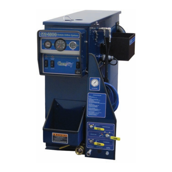
CTS 4600/4800 CDS
Hot Carbonating Truckmount
System Owner's Manual
Manufactured Exclusively for
HydraMaster North America, Inc.
th
11015 47
Avenue West, Mukilteo, Washington 98275
MAN-33193 Rev. 1, November 5, 2010
(000-182-700)
No part of this manual may be reproduced or used in any form or by any means (i.e. graphic, electronic, photocopying
or electronic retrieval systems) without the express written permission of HydraMaster North America, Inc.
All rights reserved. © 2010 HydraMaster North America, Inc.
Advertisement
Table of Contents

Related Manuals for HydraMaster ChemDry CTS 4600 CDS


Summary of Contents for HydraMaster ChemDry CTS 4600 CDS
- Page 1 No part of this manual may be reproduced or used in any form or by any means (i.e. graphic, electronic, photocopying or electronic retrieval systems) without the express written permission of HydraMaster North America, Inc. All rights reserved. © 2010 HydraMaster North America, Inc.
-
Page 3: Table Of Contents
CTS 4600/4800 CDS Table of Contents GeNeRAl INfORMATION ................SeCTION 1 System Concept ..................1-2 Contact Information ................. 1-3 Warnings, Cautions and Notices ............. 1-4 Responsibilities ..................1-8 Machine Specifications ................1-9 Spare Parts lists ..................1-11 Waste Water Disposal Advisory .............. 1-12 INSTAllATION INfORMATION .............. - Page 4 CTS 4600/4800 CDS MACHINe ASSeMBlIeS AND PARTS lIST ..........SeCTION 8 Machine Assembly Parts list - Chevy - 4.8 ..........8-5 Machine Assembly Parts list - ford - 4.8 ..........8-9 Machine Assembly Parts list - Chevy - 4.6 ..........8-13 Machine Assembly Parts list - ford - 4.6 ..........
- Page 5 CTS 4600/4800 CDS HOW TO ORDeR PARTS ................SeCTION 9 Warranty Parts Orders ................9-1 Parts Orders .................... 9-1 emergencies ................... 9-1 WARRANTy INfORMATION ............... SeCTION 10 Blower ....................10-1 Vacuum Tank ..................10-1 Solution System ..................10-1 Vacuum and Solution Hoses ..............10-1 Warranty Procedure ................
- Page 6 CTS 4600/4800 CDS list of figures figure 3-1. location of Compressor Valve .............3-2 figure 3-2. location of Cleaning Switch ..............3-3 figure 3-3. location of Solution Valve ..............3-3 figure 3-4. location of Solution Out Connection ...........3-4 figure 3-5. location of Run Switch ................3-5 figure 3-6.
- Page 7 CTS 4600/4800 CDS figure 8-20. frame Assembly 4.6 - View 1 of 2 ...........8-28 figure 8-21. frame Assembly - 4.6 - View 2 of 2 ..........8-29 figure 8-22. Blower Assembly - 4.8 ..............8-31 figure 8-23. Blower Assembly - 4.6 ..............8-33 figure 8-24.
- Page 8 CTS 4600/4800 CDS CTS CDS Owner’s Manual - vi...
-
Page 9: General Information
CTS 4600/4800 CDS 1 - General Information The CTS 4600/4800 Clutch Drive System (CDS) is a highly engineered carpet cleaning and flood extraction machine, designed and manufactured for Chem Dry for use in all ford and GMC vans (2006 model year and later). The CTS CDS units, which utilize the most current technology available in solution and recovery systems, are available in four configurations: CTS 4600 CDS featuring a 45 Tuthill vacuum blower for a ford or Chevy van or... -
Page 10: System Concept
CTS 4600/4800 CDS Other features of the CTS CDS include: • full instrumentation with control console • Stainless steel Salsa heat exchanger • One 15 gallon solution tank • equipment cowling with armrests • freeze guard system • Solution hose •... -
Page 11: Contact Information
If you have any questions regarding the operation, maintenance or repair of this machine, please contact your local distributor. If your question cannot be resolved by your distributor or by the information within this manual, you may contact HydraMaster Customer Service direct using the following phone numbers. Hours... -
Page 12: Warnings, Cautions And Notices
CTS 4600/4800 CDS WArNINgS, CAUTIONS AND NOTICES HydraMaster uses this WARNING symbol throughout the manual to warn of possible injury or death. This CAuTION symbol is used to warn of possible equipment damage. This NOTICe symbol indicates that federal or state regulatory laws may apply, and also emphasizes supplemental information. - Page 13 CTS 4600/4800 CDS Warnings and Cautions specific to the CTS 4600/4800 CDS include: HOT SuRfACeS: During the operation of this equipment, many surfaces on the machine will become very hot. When near the van for any reason care must be taken not to touch any hot surface, such as heater, engine, exhaust, etc.
- Page 14 CTS 4600/4800 CDS MOVING PARTS: Never touch any part of the machine that is in motion. Severe bodily injury may result. TRANSPORTATION Of fuel CONTAINeRS: Transportation in a vehicle of any vented fuel container that presently has or has ever contained a flammable liquid is strictly forbidden by Harris Research Inc.
- Page 15 CTS 4600/4800 CDS LEVEL OPERATION: During operation, the van must be parked on level ground not to exceed + or - 10 degrees. Failure to ensure proper leveling may prevent proper internal lubrication of engine, vacuum and/or high pressure components. FREEZE PROTECTION: There is often little warning before a cold spell.
-
Page 16: Responsibilities
CTS 4600/4800 CDS rESPONSIbIlITIES Prior to the arrival of the unit, the van that it will be installed in should be delivered to the installer. Purchaser’s responsibility If you are the purchaser, it is the your responsibility to read this Owner’s Manual and to familiarize yourself with the information contained herein, paying special attention to all Warnings and Cautions. -
Page 17: Machine Specifications
CTS 4600/4800 CDS MACHINE SPECIfICATIONS frame 13” W x 68” l x 38” H Weight 575 lbs. Construction Recovery Tank Marine Aluminum with Baked- on epoxy finish Chassis Painted Steel Cowling fiberglass Power Transfer electric Clutch-driven Shaft Vacuum Blower 4600 - 45 Tuthill/M-D Tri-lobe 4800 - 47 Tuthill/M-D Tri-lobe Air Pump Thomas Compressor... - Page 18 CTS 4600/4800 CDS Recovery Tank 100 gallon High Pressure Hose 3/16” High Temperature, Lined, Vinyl Covered Hose rated to 200 psi. Standard Equipment Machine Power Console Component Power Pack Full Instrumentation Stainless Steel Solution Heating Package Fiberglass Equipment Cowling Recovery Tank Control Console Heat Exchanger System Freeze Guard System...
-
Page 19: Spare Parts Lists
CTS 4600/4800 CDS SPArE PArTS lISTS Part No. Description 000-052-166 Connector, 2” 000-052-168 Connector, 2” Plastic 000-052-226 Insert,1 1/2” NPT 000-052-227 Reducer Cuff 2” 000-087-006 lubricant, Blower 000-169-233 Compressor Relief (Pop Off) Valve 1-11: General Information... -
Page 20: Waste Water Disposal Advisory
CTS 4600/4800 CDS WASTE WATEr DISPOSAl ADvISOrY There are laws in most communities prohibiting the dumping of recovered “gray” water from carpet cleaning in any place but a sanitary treatment system. The cleaning solution, recovered into your unit’s vacuum tank, contains materials such as detergents, and must be safely processed before entering streams, rivers and reservoirs. -
Page 21: Installation Information
CTS 4600/4800 CDS 2 - Installation Information vEHIClE PrEPArATION The preferable vehicle for a CTS CDS installation is a cargo van with a minimum payload capacity of 2,500 lbs. Be cautious when drilling any holes through the van floor. Many vans have critical components mounted directly below the van floor that could be damaged by a misplaced drill bit. - Page 22 CTS 4600/4800 CDS Installation Information: 2-2...
-
Page 23: Operating Instructions
CTS 4600/4800 CDS 3 - Operating Instructions This section of the manual contains the following instructions: „ Compressor System Background „ Solution Valve Background „ Before Operating the CTS CDS „ Start up Procedure „ Carpet or upholstery Cleaning „ flood extraction and Restoration Work „... -
Page 24: Compressor System Background
CTS 4600/4800 CDS COMPrESSOr SYSTEM bACkgrOUND The compressor pump in this machine is also referred to as an oil-less reciprocating piston pump. The performance and life of this unit is greatly dependent on the care and proper maintenance it receives (see Section 4 of this manual for daily and periodic maintenance instructions). -
Page 25: Solution Valve Background
CTS 4600/4800 CDS The compressor operates as follows: • With Cleaning switch “CleANING: (see figure 3-2) and the pressure in the solution tank is below the set point, the pressure switch will activate the clutch. This causes the compressor to turn and pressurize the system. •... -
Page 26: Before Operating The Cts Cds
CTS 4600/4800 CDS bEfOrE OPErATINg THE CTS CDS locate the unit and equipment in a well-ventilated area. exhaust fumes contain carbon monoxide and may be hazardous to your health. Do not operate this truck where the exhaust may enter any building doorway, window, vent or opening of any kind. -
Page 27: Start Up Procedure
CTS 4600/4800 CDS STArT UP PrOCEDUrE Make sure the van gear select lever is in the Park position and the emergency brake is set. Start the van engine. Turn on the CTS CDS by switching the Run switch “ON” (see figure 3-5). The rpm will automatically increase to the proper running speed. - Page 28 CTS 4600/4800 CDS If the Solution Valve is left in the “PRIMe MODe” position, the solution will evacuate from the solution tanks into the recovery tank. If the solution tanks run dry, air will fill the system. After the solution tanks have been filled with solution, purging the air from the system may require several minutes.
-
Page 29: Flood Extraction And Restoration Work
CTS 4600/4800 CDS flOOD ExTrACTION AND rESTOrATION WOrk When using equipment for flood damage, turn off the pump. This will reduce the engine power load and save on fuel consumption. Also, de-activate the heat exchangers to help prevent engine overheat problems. Position the Solution Valve to “PRIMe MODe”... -
Page 30: Shut Down Procedure
Allow the unit to run for a few minutes with the vacuum hose disconnected in order to remove moisture from the blower. Cap off the inlet(s) to the vacuum tank. Spray a HydraMaster-recommended spray lubricant into the “BlOWeR luBe PORT” for about 5 to 10 seconds while the unit is running (see figure 3-9). -
Page 31: Machine Maintenance
CTS 4600/4800 CDS 4 - Machine Maintenance This section of the manual contains maintenance instructions for: „ General Maintenance „ Van engine „ Blower „ Recovery Tank „ Compressor System „ Solution System „ freeze Guard Protection gENErAl MAINTENANCE (PErfOrMED MONTHlY) Inspect hoses. -
Page 32: Blower
CTS 4600/4800 CDS blOWEr Daily The blower’s oil level should be checked daily to ensure that the oil reaches over half of the glass in the two sight glasses. One sight glass is located in the rear of the blower and the other is located towards the front of the blower, near the drive shaft on the driver’s side (see figure 4-1). -
Page 33: Recovery Tank
CTS 4600/4800 CDS rECOvErY TANk Remove the recovery tank filter and clean (see figure 8-14 or figure 8-16). Perform this operation after every cleaning job. Remove the stainless steel blower inlet filter. Clean the stainless steel filter of debris daily. This filter is connected to the vacuum blower. -
Page 34: Solution System
CTS 4600/4800 CDS SOlUTION SYSTEM The orifice assembly is located on the side of the solution tank, in line with the outlet hose (see figure 4-2). The purpose of the orifice is to control the amount of solution being used and to filter any debris from entering the system. -
Page 35: Freeze Guard Information
CTS 4600/4800 CDS frEEzE gUArD INfOrMATION When operating the CTS CDS during the colder months of the year, ensure that you properly freeze guard the system. No part of the CTS CDS System is covered by warranty if machine damage occurs because of freezing. Water freezes at 32°... - Page 36 CTS 4600/4800 CDS freeze guard Procedure empty the solution tank. Once it has been emptied, re-install the lid and all the hoses. Turn the Solution Valve to the “PRIMe MODe” position. Turn the Compressor Valve to the “CleANING MODe” position. Position the Cleaning Mode switch to “On”.
-
Page 37: Chemical System
CTS 4600/4800 CDS 5 - Chemical System The objective of CTS 4600/4800 CDS system is to move cleaning solution from the solution tanks to the cleaning surface, and eventually back to the recovery tank (see figure 5-1 and figure 5-2). The first part of this process is to move the cleaning solution out of the solution tanks. -
Page 38: Figure 5-1. Annotated Chemical And Air Flow Diagram
CTS 4600/4800 CDS Cleaning solution is preheated as it flows through the inner coil of the figure 5-1. Annotated Chemical and Air flow Diagram engine coolant heat exchanger. Solution then flows into the blower heat 7424 COOLANT exchanger coil, which is heated by the blower exhaust. HEAT EXCHANGER The heating process begins when the engine coolant flows through the outer shell of the... -
Page 39: Figure 5-2. Solution And Exhaust Flow Diagram
CTS 4600/4800 CDS figure 5-2. Solution and Exhaust flow Diagram 7424 VACUUM GAUGE BLOWER LUBE FROM WAND BLOWER EXHAUST RECOVERY TANK BLOWER VACUUM VACUUM RELIEF VALVE FILTER APO/DRAIN FLOW FILTER BASKET HI-WATER FS-2 CUT OFF FLOAT SWITCH PUMP FS-3 FLOAT VACUUM SWITCH BLOWER... - Page 40 CTS 4600/4800 CDS Water and Chemical System: 5-4...
-
Page 41: Electrical System
CTS 4600/4800 CDS 6 - electrical System This section includes drawings for the following: „ Wiring Diagram ( figure 6-1 - figure 6-2) „ electrical Schematic (see figure 6-3) The CTS CDS electrical system operates on 12 V DC which is provided by the battery. When a new battery is installed, check that it is properly charged before installation or damage to the charging system may occur. - Page 42 CTS 4600/4800 CDS DASH ASSEMBLY (BLK) (BLK) 14(BLK) 16GA (BLK) (BLK) figure 6-1. CTS CDS (BLK) Wiring Diagram - DASH LIGHT DASH LIGHT DASH LIGHT APO RELAY CR-2 view 1 of 2 10(RED) (RED) 7397 Rev. C 16(RED/WHT) 17(WHT) 18(BLK) 19(BLK) 14 GA MODE RELAY 1(BLU)
- Page 43 CTS 4600/4800 CDS RECOVERY TANK ASSEMBLY figure 6-2. CTS CDS Wiring Diagram VAC. TANK HIGH (BLK) WATER FLOAT view 2 of 2 FS-1 (GRN) 7397 Rev. C (WHT) JACK TO THROTTLE CONTROL KIT 46(ORG/WHT) (BLK) 47(RED) (BLK) APO FLOAT CDS CLUTCH FS-2 CL-1 (WHT)
-
Page 44: Figure 6-3. Cts Cds Electrical Schematic
CTS 4600/4800 CDS VAC TANK LIGHT figure 6-3. CTS CDS Electrical Schematic 7365 Rev. A HOUR METER CLUTCH FS-1 HI-1 CL-1 VACUUM TANK FLOAT SWITCH VAC. GAUGE LIGHT TACHOMETER SI-1 MAGNETIC PICKUP PU-1 FORD: SEE THROTTLE KIT WIRING SPEED 1 000-078-405 TEMP. -
Page 45: Systems Troubleshooting
CTS 4600/4800 CDS 7 - Systems Troubleshooting This section describes the standard troubleshooting procedures in the following areas: „ Heating System „ electrical System „ Vacuum System 7-1: Systems Troubleshooting... -
Page 46: Heating System
CTS 4600/4800 CDS HEATING SYSTEM 1.0. Vehicle overheats and shuts off CTS CDS Refer to vehicle dealer for diagnosis and repair. 2.0. Vehicle overheats 2.1. Faulty thermostat in Refer to dealer vehicle. 2.2. Faulty water pump on Refer to dealer vehicle 2.3. -
Page 47: Miscellaneous
CTS 4600/4800 CDS 4.0. System attains normal heat but drops off sharply 4.1. Solution flow at cleaning Test flow of tool. Repair or replace as necessary. tool is too high. Orifice in tool is too large or worn out. 4.2. The rpm of machine is Adjust as necessary. -
Page 48: Electrical System
CTS 4600/4800 CDS ElECTrICAl SYSTEM 1.0. CTS CDS will not turn on 1.1. The main power fuse has Remove cowling and engine cover and check all wiring blown. from the power source back to the console for damage. Replace fuse only after locating the problem that caused the fuse to blow. -
Page 49: Vacuum Blower System
CTS 4600/4800 CDS vACUUM blOWEr SYSTEM 1.0. Weak vacuum at tool. gauge reads normal (10” Hg to 14” Hg) 1.1. Clogged hoses or tool Disconnect hoses and carefully check for an tube. obstruction. 1.2. excessive length of Make sure machine is rated for the conditions under hoses connected to which it is being operated. - Page 50 CTS 4600/4800 CDS 5.0. vacuum blower is locked and will not turn 5.1. The machine has been Spray penetrating oil into blower and let sit for at least unused for a period of 1 hour. Then very carefully use pipe wrench on outer time and the blower was diameter of pulley on blower shaft and attempt to not properly lubricated...
- Page 51 CTS 4600/4800 CDS 8 - Machine Assemblies and Parts list This section contains all the assemblies and top level parts lists associated with the CTS CDS: „ „ Machine Assembly Parts list - Chevy - 4.8 Chemical Tray Assembly Parts list „...
- Page 52 CTS 4600/4800 CDS figure 8-1. Machine Assembly - Chevy - 4.8 view 1 of 3 7390 Machine Assemblies and Parts lists: 8-2...
- Page 53 CTS 4600/4800 CDS figure 8-2. Machine Assembly - Chevy - 4.8 view 2 of 3 7390 8-3: Machine Assemblies and Parts lists...
- Page 54 CTS 4600/4800 CDS figure 8-3. Machine Assembly - Chevy - 4.8 view 3 of 3 7390 Machine Assemblies and Parts lists: 8-4...
- Page 55 CTS 4600/4800 CDS Machine Assembly Parts list - Chevy - 4.8 Item Part Number Description Item Part Number Description 601-060-123 Assembly, Recovery Tank, Chevy 000-068-459 Hose, 3/4” I.D. Green Stripe 601-050-150 Assembly. Salsa Core With Insulation 000-068-459 Hose, 3/4” I.D. Green Stripe 610-015-035 Assembly, 15 Gallon Solution Tank 000-068-200...
- Page 56 CTS 4600/4800 CDS figure 8-4. Machine Assembly - ford - 4.8 view 1 of 3 7409 Machine Assemblies and Parts lists: 8-6...
- Page 57 CTS 4600/4800 CDS figure 8-5. Machine Assembly - ford - 4.8 view 2 of 3 7409 8-7: Machine Assemblies and Parts lists...
- Page 58 CTS 4600/4800 CDS figure 8-6. Machine Assembly - ford - 4.8 view 3 of 3 7409 Machine Assemblies and Parts lists: 8-8...
- Page 59 CTS 4600/4800 CDS Machine Assembly Parts list - ford - 4.8 Item Part Number Description Item Part Number Description 601-060-123 Assembly, Recovery Tank, ford 000-068-250 Hose, 1” I.D. Green Stripe 601-050-150 Assembly. Salsa Core With Insulation 000-068-250 Hose, 1” I.D. Green Stripe 610-015-035 Assembly, 15 Gallon Solution Tank 000-068-250...
- Page 60 CTS 4600/4800 CDS figure 8-7. Machine Assembly - Chevy - 4.6 view 1 of 3 7391 Machine Assemblies and Parts lists: 8-10...
- Page 61 CTS 4600/4800 CDS figure 8-8. Machine Assembly - Chevy - 4.6 view 2 of 3 7391 8-11: Machine Assemblies and Parts lists...
- Page 62 CTS 4600/4800 CDS figure 8-9. Machine Assembly - Chevy - 4.6 view 3 of 3 7391 Machine Assemblies and Parts lists: 8-12...
- Page 63 CTS 4600/4800 CDS Machine Assembly Parts list - Chevy - 4.6 Item Part Number Description Item Part Number Description 601-060-123 Assembly, Recovery Tank, Chevy 000-068-459 Hose, 3/4” I.D. Green Stripe 601-050-150 Assembly. Salsa Core With Insulation 000-068-459 Hose, 3/4” I.D. Green Stripe 610-015-035 Assembly, 15 Gallon Solution Tank 000-068-200...
- Page 64 CTS 4600/4800 CDS figure 8-10. Machine Assembly - ford - 4.6 view 1 of 3 7410 Machine Assemblies and Parts lists: 8-14...
- Page 65 CTS 4600/4800 CDS figure 8-11. Machine Assembly - ford - 4.6 view 2 of 3 7410 8-15: Machine Assemblies and Parts lists...
- Page 66 CTS 4600/4800 CDS figure 8-12. Machine Assembly - ford - 4.6 view 3 of 3 7410 Machine Assemblies and Parts lists: 8-16...
- Page 67 CTS 4600/4800 CDS Machine Assembly Parts list - ford - 4.6 Item Part Number Description Item Part Number Description 601-060-123 Assembly, Recovery Tank, ford 000-068-250 Hose, 1” I.D. Green Stripe 601-050-150 Assembly. Salsa Core With Insulation 000-068-250 Hose, 1” I.D. Green Stripe 610-015-035 Assembly, 15 Gallon Solution Tank 000-068-250...
- Page 68 CTS 4600/4800 CDS figure 8-13. recovery Tank Assembly - Chevy view 1 of 2 7392 Machine Assemblies and Parts lists: 8-18...
- Page 69 CTS 4600/4800 CDS figure 8-14. recovery Tank Assembly - Chevy view 2 of 2 7392 HIDDEN HIDDEN 2X HIDDEN 2X HIDDEN HIDDEN 8-19: Machine Assemblies and Parts lists...
- Page 70 CTS 4600/4800 CDS recovery Tank Assembly Parts list - Chevy Item Part Number Description Item Part Number Description label, ANSI Warning - Park Position Machine 000-106-046 Plug, 1-1/4” NPT label, ANSI Warning - large 000-106-019 Plug, 1-1/2” NPT See figure 8-17 Assembly, Recovery Tank Cover - 100 Gallon 000-094-113 Nut, 1/4”-20uNC Neoprene Wellnut...
- Page 71 CTS 4600/4800 CDS figure 8-15. recovery Tank Assembly - ford view 1 of 2 7411 8-21: Machine Assemblies and Parts lists...
- Page 72 CTS 4600/4800 CDS figure 8-16. recovery Tank Assembly - ford view 2 of 2 7411 HIDDEN HIDDEN 2X HIDDEN 2X HIDDEN HIDDEN Machine Assemblies and Parts lists: 8-22...
- Page 73 CTS 4600/4800 CDS recovery Tank Assembly Parts list - ford Item Part Number Description Item Part Number Description label, ANSI Warning - Park Position Machine 000-106-046 Plug, 1-1/4” NPT label, ANSI Warning - large 000-106-019 Plug, 1-1/2” NPT See figure 8-17 Assembly, Recovery Tank Cover - 100 Gallon 000-094-113 Nut, 1/4”-20uNC Neoprene Wellnut...
-
Page 74: Figure 8-17. Recovery Tank Cover Assembly
CTS 4600/4800 CDS figure 8-17. recovery Tank Cover Assembly 7151 recovery Tank Cover Assembly Parts list Item Part Number Description Item Part Number Description 000-041-447 Cover, Weldment - 100 uRT 000-094-063 Nut, #6-32uNC Nylock 000-078-039 Vacuum Inlet Stopper 000-052-222 elbow, 2” Barb X 2” fPT 000-057-015 Gasket, 1-1/2”... -
Page 75: Figure 8-18. Frame Assembly - 4.8 - View 1 Of 2
CTS 4600/4800 CDS figure 8-18. frame Assembly - 4.8 - view 1 of 2 7393 The blower and compressor are hidden in this view for clarity. 8-25: Machine Assemblies and Parts lists BLOWER AND COMPRESSOR HIDDEN FOR CLARITY. - Page 76 CTS 4600/4800 CDS figure 8-19. frame Assembly 4.8 - view 2 of 2 7393 BLOWER AND COMPRESSOR HIDDEN FOR CLARITY. The drive shaft, drive shaft pulleys and drive shaft belts are hidden in this view for clarity. DRIVE SHAFT, DRIVE SHAFT PULLEYS, AND DRIVE SHAFT BELTS HIDDEN FOR CLARITY. Machine Assemblies and Parts lists: 8-26...
- Page 77 CTS 4600/4800 CDS frame Assembly - 4.8 - Parts list Item Part Number Description Item Part Number Description 000-008-020 Bearing, Pillow Block - 1-3/16” Bore 000-143-018 Screw, 3/8-16uNC X 1” HH - Grade 8 000-010-052 Belt, Polychain GT 000-143-098 Screw,3/8-16 X 2 1/2”HHCS 000-143-132 Screw, #10-24uNC X 0.75”...
- Page 78 CTS 4600/4800 CDS figure 8-20. frame Assembly 4.6 - view 1 of 2 7394 The blower and compressor are hidden in this view for clarity. Machine Assemblies and Parts lists: 8-28...
- Page 79 CTS 4600/4800 CDS figure 8-21. frame Assembly - 4.6 - view 2 of 2 7394 The drive shaft, drive shaft pulleys and drive shaft belts are hidden in this view for clarity. 8-29: Machine Assemblies and Parts lists...
- Page 80 CTS 4600/4800 CDS frame Assembly - 4.6 - Parts list Item Part Number Description Item Part Number Description 000-008-020 Bearing, Pillow Block - 1-3/16” Bore 000-143-018 Screw, 3/8-16uNC X 1” HH - Grade 8 000-010-052 Belt, Polychain GT 000-143-098 Screw,3/8-16 X 2 1/2”HHCS 000-010-065 Belt, #9345 Pump Drive 000-143-132...
- Page 81 CTS 4600/4800 CDS figure 8-22. blower Assembly - 4.8 7395 8-31: Machine Assemblies and Parts lists...
- Page 82 CTS 4600/4800 CDS blower Assembly - 4.8 Parts list Item Part Number Description Item Part Number Description 000-001-042 Adapter, Blower Outlet 000-109-009 Pulley, 2.75” X 0.88” Pump Drive 000-001-090 Adapter, Blower Inlet 000-109-057 Pulley, 40 Tooth Gt2 8mx-10s-21 engine and Blower 000-015-801 Bracket, Blower Mounting 000-111-147...
- Page 83 CTS 4600/4800 CDS figure 8-23. blower Assembly - 4.6 7396 8-33: Machine Assemblies and Parts lists...
- Page 84 CTS 4600/4800 CDS blower Assembly - 4.6 - Parts list Item Part Number Description Item Part Number Description 000-001-043 Adapter, Blower Outlet 000-109-009 Pulley, 2.75” X 0.88” Pump Drive 000-001-090 Adapter, Blower Inlet 000-109-057 Pulley, 40 Tooth Gt2 8mx-10s-21 engine and Blower 000-015-722 Bracket, Angle Tab 000-111-145...
-
Page 85: Figure 8-24. Compressor Assembly
CTS 4600/4800 CDS figure 8-24. Compressor Assembly 7398 8-35: Machine Assemblies and Parts lists... - Page 86 CTS 4600/4800 CDS Compressor Assembly Parts list Item Part Number Description Item Part Number Description 000-015-923 Bracket, Compressor Mount- Weldment 000-111-173 Compressor - Thomas 000-020-064 Spacer, Compressor Clutch 000-143-001 Screw, 1/4”-20uNC X 0.75” lg. HH 000-036-010 Clutch, electric 000-143-013 Screw, 5/16”-18uNC X 1.00” lg. Grade 8 000-052-085 elbow, 1/4”...
-
Page 87: Figure 8-25. Dash Box Assembly
CTS 4600/4800 CDS figure 8-25. Dash box Assembly 7399 8-37: Machine Assemblies and Parts lists... - Page 88 CTS 4600/4800 CDS Dash box Assembly Parts list Item Part Number Description Item Part Number Description 000-013-025 Dash Box - Weldment 000-143-046 Screw, #6-32 X .500” lg. PHP 000-015-183 Bracket, Grounding Bus 000-143-114 Screw, #10-24uNC X 0.50” lg. fHP 000-060-002 Grommet, large Wiring 000-143-126 Screw, #10-24uNC X 0.50”...
-
Page 89: Figure 8-26. Dash Panel Assembly
CTS 4600/4800 CDS figure 8-26. Dash Panel Assembly 7400 Dash Panel Assembly Parts list Item Part Number Description Item Part Number Description 000-012-001 Block, 4 lead electrical Terminal 000-081-321 label, Dash - upper 000-018-004 Breaker, 25 Amp Circuit 000-081-322 label, Dash - lower 000-052-084 elbow, 1/8”... - Page 90 CTS 4600/4800 CDS figure 8-27. Instrument Panel Assembly - Chevy - view 1 of 2 7402 APO OPTION Machine Assemblies and Parts lists: 8-40...
- Page 91 CTS 4600/4800 CDS figure 8-28. Instrument Panel Assembly - Chevy - view 2 of 2 7402 8-41: Machine Assemblies and Parts lists...
- Page 92 CTS 4600/4800 CDS Instrument Panel Assembly Parts list - Chevy Item Part Number Description Item Part Number Description See figure 8-31 Assembly, Solution Manifold 000-057-055 Gasket, Garden Hose 000-052-423 Bushing, Modified Set Screw Orifice 000-074-048 Gauge, Air Pressure 0 - 150 psi 000-180-004 Orifice, Set Screw - 0.033”...
- Page 93 CTS 4600/4800 CDS figure 8-29. Instrument Panel Assembly - ford - view 1 of 2 7403 APO OPTION 8-43: Machine Assemblies and Parts lists...
- Page 94 CTS 4600/4800 CDS figure 8-30. Instrument Panel Assembly - ford - view 2 of 2 7403 Machine Assemblies and Parts lists: 8-44...
- Page 95 CTS 4600/4800 CDS Instrument Panel Assembly Parts list - ford Item Part Number Description Item Part Number Description See figure 8-31 Assembly, Solution Manifold 000-057-055 Gasket, Garden Hose 000-052-423 Bushing, Modified Set Screw Orifice 000-074-048 Gauge, Air Pressure 0 - 150 psi 000-180-004 Orifice, Set Screw - 0.033”...
-
Page 96: Figure 8-31. Solution Manifold Assembly
CTS 4600/4800 CDS figure 8-31. Solution Manifold Assembly Solution Manifold Assembly Parts list 7404 Item Part Number Description 000-052-095 Nipple,1/4 S/S Hex 000-052-506 Nipple, 1/4 MPT X 9/16” 000-052-691 elbow,1/4 Street S/S 000-052-696 Insert, #44 (1/4 NPT X 1/4” Barb) S/S 000-090-018 Manifold, S/S Hi PSI Chem Dry 000-169-095... -
Page 97: Figure 8-32. Chemical Tray Assembly
CTS 4600/4800 CDS figure 8-32. Chemical Tray Assembly 7405 10 4X Chemical Tray Assembly Parts list Item Part Number Description 000-015-938 Bracket, Mounting 000-015-970 Bracket, Chemical 000-081-324 label, Name 000-094-038 Nut, 5/16”-18uNC Nylock 000-143-001 Screw, 1/4”-20uNC X 0.75” lg. HH 000-143-572 Screw, 5/16-18uNC X 5/8””... -
Page 98: Figure 8-33. Coolant Heat Exchanger Assembly - Chevy
CTS 4600/4800 CDS figure 8-33. Coolant Heat Exchanger Assembly - Chevy 7406 Machine Assemblies and Parts lists: 8-48... - Page 99 CTS 4600/4800 CDS Coolant Heat Exchanger Assembly Parts list - Chevy Item Part Number Description Item Part Number Description 000-015-745 Bracket, After Burner Mounting Saddle 000-094-038 Nut, 5/16”-18uNC Nylock 000-015-971 Bracket, Coolant Heat exchanger 000-108-102 Protector, Coolant Heat exchanger 000-033-123 Clamp, After Burner Mount 000-108-131 Protector, Heat exchanger Pad...
-
Page 100: Figure 8-34. Coolant Heat Exchanger Assembly - Ford
CTS 4600/4800 CDS figure 8-34. Coolant Heat Exchanger Assembly - ford 7407 Machine Assemblies and Parts lists: 8-50... - Page 101 CTS 4600/4800 CDS Coolant Heat Exchanger Assembly Parts list - ford Item Part Number Description Item Part Number Description 000-015-745 Bracket, After Burner Mounting Saddle 000-094-038 Nut, 5/16”-18uNC Nylock 000-015-971 Bracket, Coolant Heat exchanger 000-108-102 Protector, Coolant Heat exchanger 000-033-123 Clamp, After Burner Mount 000-108-131 Protector, Heat exchanger Pad...
-
Page 102: Figure 8-35. Heat Exchanger Assembly
CTS 4600/4800 CDS figure 8-35. Heat Exchanger Assembly 7663 000-106-124 000-106-173 Heat Exchanger Assembly Parts list Item Part Number Description 000-108-140 Protector, Salsa Insulation 000-052-674 elbow, 3 Rubber w/Clamps 000-052-649 elbow, 3 O.D. X O.065” Wall 4.5” R w/2” 601-050-151 Assembly, Salsa Core 1/4”... -
Page 103: Figure 8-36. Dura-Flow Automatic Pump Out (Apo) Assembly
CTS 4600/4800 CDS figure 8-36. Dura-flow Automatic Pump Out (APO) Assembly 7753 Rev. B 8-53: Machine Assemblies and Parts lists... - Page 104 CTS 4600/4800 CDS Dura-flow Automatic Pump Out (APO) Assembly Parts list Item Part Number Description Item Part Number Description 000-091-042 Motor, Bison 438 Series 000-143-074 Screw, 1/4-20uNC X 0.50” lg. Hex Head Self-Tapping 000-052-757 Insert, 1 NPT X 3/4” elbow 000-052-131 elbow, 1NPT X 1”...
-
Page 105: Figure 8-37. Vacuum Relief Valve Assembly
CTS 4600/4800 CDS figure 8-37. vacuum relief valve Assembly 6894 Rev. A vacuum relief valve Assembly Parts list Item Part Number Description Item Part Number Description 000-155-026 Spring, Vacuum Relief Valve 000-015-182 Bracket, Vacuum Relief Valve 000-143-198 Screw, 3/8”-16uNC X 4” lg. Hex Head - full Thread 000-027-032 Cap, Spun Vaccum Relif Valve 000-094-077... - Page 106 CTS 4600/4800 CDS figure 8-38. Pass Thru Assembly 5623 Rev. B Pass Thru Assembly Parts list Item Part Number Description 000-125-182 Tube, Pass Through 000-041-200 Cover, 4 Round Abs-Mod. -Pass Through 000-143-537 Screw, #10 X 1.5 lg. Pan Head Sheet Metal 000-033-032 Clamp, CDS Throttle Cable 000-025-008...
-
Page 107: Figure 8-39. 15 Gallon Solution Tank Assembly
CTS 4600/4800 CDS figure 8-39. 15 gallon Solution Tank Assembly 6163 Rev. C TO COMPRESSOR TO COMPRESSOR TO HEAT EXCHANGER 8-57: Machine Assemblies and Parts lists... - Page 108 CTS 4600/4800 CDS 15 gallon Solution Tank Assembly Parts list Item Part Number Description Item Part Number Description 000-180-021 Orifice, Set Screw #10-32 UNF X N0.052” 000-015-869 Bracket, 15 Gallon Chemical Tank 000-052-697 Socket, In S/S 90° Barb 000-049-137 filter, In-line Quick Connect 000-052-698 Socket, Out S/S 90°...
- Page 109 CTS 4600/4800 CDS 2008 - 2010 gM Throttle kit Parts list (P/N 000-078-430) gM Cowling Assembly, 2003 – 2009 Parts list (P/N 601-020-008) Part Number Description Part Number Description 000-037-015 Terminal, 5/16 Ring-1 000-041-139 Cowling, Chevy Gray 000-037-071 Terminal, fully Insulated 000-131-060 Trimlok Seal, 3/4”...
- Page 110 CTS 4600/4800 CDS 2006 - 2010 ford Throttle kit Parts list (P/N 000-078-405) Part Number Description Part Number Description 000-084-011 lamp, Mx 550 Red led Indicator - Mini w/35” leads 000-037-003 Connector, Butt-14/16 000-037-004 Closed end Conn-Medi 000-084-012 yellow light, Dash Panel 000-037-005 Closed end Connector 000-131-021...
-
Page 111: Figure 8-40. Hose Routings - Chevy - View 1 Of 3
CTS 4600/4800 CDS figure 8-40. Hose routings - Chevy - view 1 of 3 8-61: Machine Assemblies and Parts lists... - Page 112 CTS 4600/4800 CDS figure 8-41. Hose routings - Chevy - view 2 of 3 Machine Assemblies and Parts lists: 8-62...
- Page 113 CTS 4600/4800 CDS figure 8-42. Hose routings - Chevy - view 3 of 3 8-63: Machine Assemblies and Parts lists...
- Page 114 CTS 4600/4800 CDS Hose routings - Chevy Item Part Number Description Item Part Number Description 000-068-015 Hose, 1/4 Rubber - Bulk 000-068-131 Hose, 1/4 I.D. High Temp 000-068-015 Hose, 1/4 Rubber - Bulk 000-068-459 Hose, 3/4 I.D., Green Stripe 000-068-069 Hose, 3/4 I.D.
-
Page 115: Figure 8-43. Hose Routings - Ford - View 1 Of 3
CTS 4600/4800 CDS figure 8-43. Hose routings - ford - view 1 of 3 8-65: Machine Assemblies and Parts lists... - Page 116 CTS 4600/4800 CDS figure 8-44. Hose routings - ford - view 2 of 3 Machine Assemblies and Parts lists: 8-66...
-
Page 117: Figure 8-45. Hose Routings - Ford - View 3 Of 3
CTS 4600/4800 CDS figure 8-45. Hose routings - ford - view 3 of 3 8-67: Machine Assemblies and Parts lists... - Page 118 CTS 4600/4800 CDS Hose routings - ford Item Part Number Description Item Part Number Description 000-068-015 Hose, 1/4 Rubber - Bulk 000-068-131 Hose, 1/4 I.D. High Temp 000-068-015 Hose, 1/4 Rubber - Bulk 000-068-459 Hose, 3/4 I.D., Green Stripe. 000-068-069 Hose, 3/4 I.D.
- Page 119 We shall always endeavor to be fair in our evaluation of your warranty claim and shall provide you with a complete analysis of our findings. HydraMaster warranty covers only defective materials and/or workmanship for the periods listed. Diagnostic reimbursement is specifically excluded.
- Page 120 CTS 4600/4800 CDS How to Order Parts: 9-2...
- Page 121 Such causes listed in this section shall constitute abuse or neglect. blOWEr • failure to lubricate impellers daily with a HydraMaster-recommended lubricant, to lubricate bearings, to maintain proper oil levels, or to use the correct oil grade and viscosity as recommended in blower manual.
- Page 122 CTS 4600/4800 CDS Warranty Information: 10-2...
Need help?
Do you have a question about the ChemDry CTS 4600 CDS and is the answer not in the manual?
Questions and answers