Table of Contents
Advertisement
Quick Links
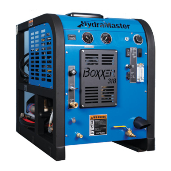
Boxxer 318 - 2015
Owner's Manual
HydraMaster
th
11015 47
Avenue West
Mukilteo, Washington 98275
MAN-46585 Rev. A, May 20, 2015
(P/N 000-182-418)
No part of this manual may be reproduced or used in any form or by any means (i.e. graphic, electronic, photocopying or electronic
retrieval systems) without the express written permission of HydraMaster. Specifications and information in this document are
subject to change without prior notice. All rights reserved. © 2015 HydraMaster
*000-182-418*
Advertisement
Table of Contents

Related Manuals for HydraMaster hydramaster


Summary of Contents for HydraMaster hydramaster
- Page 1 No part of this manual may be reproduced or used in any form or by any means (i.e. graphic, electronic, photocopying or electronic retrieval systems) without the express written permission of HydraMaster. Specifications and information in this document are subject to change without prior notice. All rights reserved. © 2015 HydraMaster...
-
Page 3: Table Of Contents
Table of Contents GENERAL INFORMATION ................SECTION 1 Contact Information ................1-3 Warnings, Cautions and Notices ............1-4 Responsibilities ................. 1-8 System Concept ................1-10 Machine Specifications ..............1-11 High Altitude Operation ..............1-13 Local Water Precautions ..............1-13 CLEANING AND CHEMICALS ..............SECTION 2 Precautions .................. - Page 4 TROUBLESHOOTING ................. SECTION 7 Heating System ................. 7-2 Chemical System ................7-3 Engine....................7-5 High Pressure System ............... 7-9 Vacuum System ................. 7-11 ASSEMBLIES AND PARTS LIST ..............SECTION 8 Console Assembly Parts List ............. 8-8 Frame Assembly Parts List ..............8-11 Engine Assembly Parts List ...............
- Page 5 WARRANTY INFORMATION ............... SECTION 10 Blower ....................10-1 High Pressure Water Pump .............. 10-1 Recovery Tank .................. 10-2 Chemical System ................10-2 Control Panel ..................10-2 Vacuum and Solution Hoses ............. 10-2 Cleaning Wand ................. 10-2 Water Heating System ..............10-2 Hard Water Deposits ................
- Page 6 List of Figures Figure 1-1. Hard Water Map of Mainland United States ........... 1-14 Figure 3-1. Location of Throttle, Choke and Pump-In/Pump Clutch Switch ....3-1 Figure 3-2. Front View of Boxxer 318 Console ............3-2 Figure 3-3. Side View of Boxxer 318 Console ............3-3 Figure 4-1.
- Page 7 Figure 8-20. Differential Check Valve Assembly ............8-27 Figure 8-21. By-Pass Valve Assembly ..............8-28 Figure 8-22. Orifice Assembly .................. 8-29 Figure 8-23. Idler Pulley Assembly ................8-30 Figure 8-24. Exhaust Assembly ................8-31 Figure 8-25. 65 Gallon Universal Recovery Tank (URT) Assembly View 1 of 2 ...................
- Page 8 Boxxer 318 Owner’s Manual: vi...
- Page 9 1- General Information The Boxxer™ 318 is a carefully engineered truckmount by HydraMaster for carpet cleaning, upholstery cleaning water extraction/restoration as well. The system utilizes an internal combustion engine to provide the power necessary to turn both a blower (also referred to as a vacuum pump) and a high pressure water pump.
-
Page 10: General Information
It is the purpose of this manual to help the technician properly understand, maintain and service the truckmount. By following these guidelines carefully, you can expect years of reliable operation. This section contains the following information: „ Contact Information „ Warnings, Cautions and Notices „... -
Page 11: Contact Information
To find a local distributor, please visit our website at http://hydramaster.com/HowToBuy/DealerLocator.aspx If your question cannot be resolved by your distributor or by the information within this manual, you may contact HydraMaster direct using the following phone numbers. HOURS TELEPHONE NUMBERS... -
Page 12: Warnings, Cautions And Notices
WARNINGS, CAUTIONS AND NOTICES HydraMaster uses this WARNING symbol throughout the guide to warn of possible injury or death. This CAUTION symbol is used to warn of possible equipment damage. This NOTICE symbol indicates that federal or state regulatory laws may apply, and also emphasizes supplemental information. - Page 13 Transporting a vented fuel container that presently contains, or has ever contained in the past, a flammable liquid is strictly forbidden by HydraMaster and by federal and state regulations. Doing so will increase the risk of fire and explosion. Serious injury or death may result.
- Page 14 Never smoke in or around the truckmount. Doing so will increase the risk of fire and explosion. Serious injury or death may result. During the operation of the truckmount the exhaust system will become extremely hot. Keep all flammable materials away from the truckmount exhaust system. Failure to do so will increase the risk of fire and explosion.
- Page 15 Never allow water to freeze inside the truckmount. Serious component damage will occur. Perform all freeze guarding procedures outlined in the digital Owner’s Manual. Many vehicles have critical components mounted directly below the floor that can easily be damaged. Before drilling holes in the floor of the vehicle, inspect the underside of the vehicle for critical components.
-
Page 16: Responsibilities
RESPONSIBILITIES The Purchaser’s Responsibilities Prior to purchasing a van, ensure that the payload is suitable for all of the equipment that will be installed and transported. This includes and is not limited to: the truckmount, recovery tanks, fresh water tanks and on-board water, hose reels, hoses, cleaning tools, chemicals, drying equipment, etc. - Page 17 • Ensure proper connection of the fuel lines. • Ensure proper connection and installation of the battery. Verify that the battery is in accordance with HydraMaster’s recommendation. • Check the pump, vacuum blower and engine oil levels prior to starting the truckmount.
-
Page 18: System Concept
SYSTEM CONCEPT The system utilizes an internal combustion engine to provide the power necessary to turn both a vacuum pump and a high pressure water pump. The heat of the engine and blower exhausts is transferred to the high pressure water in the finned tube heat exchanger of the system. -
Page 19: Machine Specifications
MACHINE SPECIFICATIONS Frame Dimensions 24.0" W x 31” H x 36" D Weight 570 lbs Engine- Briggs and Oil Type Synthetic 5W-30 Stratton Vanguard 18HP Capacity Approx. 1 1/2 quarts (48 oz.) when changing oil and filter Engine rpm 3,150 rpm Fuel Consumption 1.0 gph Ignition... - Page 20 Standard Equipment High Pressure Hose 1/4" High Temperature Lined/ Vinyl Cover - 100 ft. Vacuum Hose 2" Vacuum Hose- 100 ft. 1-1/2" Wand Whip Line- 10 ft. Recovery Tank 65 gallon MaxAir Universal Tank Cleaning Wand Stainless Steel S-bend Replaceable Grip Rebuildable Solution Valve Chemical Jug 5 gallon...
-
Page 21: High Altitude Operation
Hard Water Advisory HydraMaster recognizes that any hard water deposits which might occur within the water system of our truckmounts is a serious problem. The precision technology of truckmount heat exchanger systems is intolerant of any foreign material. Hard water deposits will ultimately decrease the performance of the system and are expected to seriously lower the reliability of the machine. -
Page 22: Figure 1-1. Hard Water Map Of Mainland United States
Hard Water Area Map The hard water map, shown in Figure 1-1, defines hard water areas in the continental United States which compromise fluid related components such as hoses, fittings, heaters, pumps, valves and water-cooled engines. For other countries, hard water area maps can be obtained from geological societies. - Page 23 Cleaning efficiency and equipment life is increased, chemical use decreased, and the appearance of cleaned carpets enhanced when water softeners are incorporated in hard water areas. HydraMaster strongly urges the use of water softener units with the Boxxer 318 in areas exceeding 3.0 grains per gallon.
- Page 24 HydraMaster makes an APO System which can be ordered with new equipment or installed later. When properly configured, the systems will continuously monitor the level of waste water and pump it out simultaneously with the cleaning operation.
-
Page 25: Cleaning And Chemicals
HydraMaster’s ClearWater Rinse™ has been formulated to protect vital components. HydraMaster will not warranty parts that have been damaged from using acid products that have obviously caused failures. 2-1: Chemicals and Cleaning... -
Page 26: Preparing The Carpet For Extraction
Relying on the rinse detergent to do the majority of the cleaning will result in overly long dry times and excess detergent residue left in the carpet. HydraMaster recommends the use of our pre-sprays: Fastbreak™ for residential carpet and Blitz™ for commercial carpet needs. -
Page 27: Overwetting
For more information about HydraMaster’s complete chemical product line, visit this webpage: http://hydramaster.com/Products/Chemicals.aspx OVERWETTING Overwetting is an annoyance to all concerned. Extended drying times will leave the customer with a negative impression of both the cleaning company and the process used. -
Page 28: Cleaning Tool Tips
CLEANING TOOL TIPS Wands With a wand, keep cleaning strokes short, front to back, and run a “dry pass”. After pulling the wand for a strip of 3 or 4 ft long with the solution trigger activated, go back up to the top of the stroke, and make a “dry “ pass [i.e. no solution flowing]. This gives the wand a second chance to pick up the solution on the carpet. - Page 29 2-5: Chemicals and Cleaning...
- Page 30 Chemicals and Cleaning: 2-6...
- Page 31 ® RX-20 Tool Before turning on the RX-20, adjust the handle; it should rest right below or even with the bottom of your pants’ front pockets, with the tool resting flat on the floor. Take your time in adjusting the tool’s height; make sure the head of the tool is flat with the floor while you are holding the handle.
- Page 32 Upholstery Tool - DriMaster 3 Use the upholstery tool on small rugs and furniture. When you clean rugs, be sure that the temperature and chemicals are safe for that particular type of rug. As with the larger tools, do not leave the surface of the upholstery too wet. Adjust the volume of water on the tool without it touching any surface: the water should just barely come out of the tool before the vacuum pulls it back in.
-
Page 33: Operating Instructions
3 - Operating Instructions START-UP PROCEDURE Perform all daily and periodic maintenance as specified in Section 4 of this Owner’s Manual. Connect a garden hose to supply water to the truckmount. If used, turn the “PUMP-IN” switch to the “ON” position (see Figure 3-1). The water box must be full prior to starting the truckmount. -
Page 34: Figure 3-2. Front View Of Boxxer 318 Console
Pressure Gauge Optional Auto Vacuum Gauge Pump-Out Switch Temperature Knob Chemical Selection Valve Chemical Metering Control Knob Blower Lube Port Figure 3-2. Front View of Boxxer 318 Console Operating Instructions: 3-2... -
Page 35: Figure 3-3. Side View Of Boxxer 318 Console
Press the “PUMP CONTROL” switch to engage the pump clutch for carpet cleaning or upholstery cleaning as follows: Switch to the “HP Only” if connected to a fresh water supply from a building. Switch to the “HP ON & Pump-In ON” if connected to a fresh water tank. Set the temperature to the desired level on the “TEMPERATURE”... -
Page 36: Water Extraction Procedure
Cap off the inlet(s) to the vacuum tank. Spray a HydraMaster-recommended spray lubricant into the “BLOWER LUBE PORT” for about 5 to 7 seconds while the unit is running (see Figure 3-2). Allow machine to run additional 2 to 5 minutes under load to flush off lubricant. -
Page 37: Machine Maintenance
Owner’s Guide. Records of maintenance must be kept and copies may be required to be furnished to HydraMaster before the warranty is honored. It is recommended that you affix a copy of the log on the vehicle door near your unit for convenience and to serve as a maintenance reminder. -
Page 38: Operational Maintenance
• Inspect the truckmount for water and oil leaks, loose electrical connections, etc. and repair as needed. • Lubricate the blower lube port with HydraMaster-recommended spray lubricant. Weekly Maintenance • Inspect the recovery tank filters for tears, holes, etc. Repair or replace as needed. - Page 39 250 Hours • Check coupler element (rubber insert) for cracks or wear. Replace as necessary. 500 Hours • Change the blower oil. • Change the high pressure pump oil. • Check the engine valve clearance (intake and exhaust 0.004” - 0.006”) •...
-
Page 40: High Pressure Pump Maintenance
HIGH PRESSURE PUMP MAINTENANCE Daily Check the oil level and the condition of the oil. The oil level should be up to the center of the sight glass on the rear of the pump or between the “MIN” and “MAX” lines on the dipstick. -
Page 41: Figure 4-1. Servicing The Valves
Valve Maintenance (See Figure 4-1) Using a 22-mm wrench or socket, remove all six valve caps on the manifold of the pump. Examine each valve cap O-ring for cuts or distortions and replace if worn. Using needle nose pliers, remove the suction and delivery check valves. The valve assembly usually stays together when removing. - Page 42 Replace old valves with new valves by placing the assembly in the valve chamber. Press down firmly on the top of the valve assembly. Replace valve caps by applying LOCTITE® 243 to valve cap and torque to 33 ft- lbs. Removing and Replacing Pump Manifold Remove the manifold of the pump by taking a 5-mm Allen head wrench and removing the eight head bolts.
- Page 43 Torque to 4.5 ft-lbs. Servicing the Crankcase While the manifold and plungers are removed, rotate the crankshaft by hand. Closely examine the crankcase oil seals for drying, cracking or leaking. Consult the local HydraMaster distributor if crankcase servicing is necessary. 4-7: Machine Maintenance...
-
Page 44: Vacuum System Maintenance
Capping off the inlet(s) to the recovery tank. Spraying a HydraMaster-recommended spray lubricant into the “BLOWER LUBE PORT” for about 5 to 7 seconds while the unit is running. Uncapping the inlet(s) and run the unit for another minute to allow the blower to cool down. -
Page 45: Descaling Procedure (Required)
DESCALING PROCEDURE (REQUIRED) Scale deposits on the interior of the heating system can cause a noticeable loss in heating performance. Deposits of this kind result from hard water deposits. The frequency with which descaling procedures are required will vary. If the area has particularly hard water, you may have to descale often. -
Page 46: Freeze Guarding
FREEZE GUARDING To avoid permanent damage to the truckmount, it is imperative to follow the freeze guard procedure whenever the possibility of freezing temperatures exists. When disposing of antifreeze follow local laws and regulations. Do not discard into storm sewers, septic systems, or onto the ground. Antifreeze is harmful or fatal if swallowed. - Page 47 The reclaimed antifreeze solution may be used three times before being discarded. To freeze guard the hoses and wand perform step 7 with the items to be freeze guarded attached. Recovering Antifreeze for Re-Use Attach all hoses and wands which have been freeze guarded to the truckmount. Attach the incoming water source to the front of the truckmount.
-
Page 48: Tensioning The Pump Drive Belt
TENSIONING THE PUMP DRIVE BELT Remove the Boxxer 318 grill to gain access to the idler pulley. Loosen but do not remove the 2 ¼” long bolt (P/N 000-143-041) on the idler pulley. See Section 9 in the Owner’s Manual. Remove the right cover of the machine to gain access to the tensioning screw. -
Page 49: Water And Chemical System
Finally, the water joins the chemical where the solution is created. The chemical is pressurized by the HydraMaster diaphragm chemical pump attached to the head of the water pump. This pump pulls the chemical from the jug through the chemical meter. - Page 50 Water and Chemical System: 5-2...
-
Page 51: Figure 5-1. Flow Diagram - View 1 Of 3
Figure 5-1. Flow Diagram - View 1 of 3 000-179-038 Rev. C 5-3: Water and Chemical System... -
Page 52: Figure 5-2. Flow Diagram - View 2 Of 3
Figure 5-2. Flow Diagram - View 2 of 3 000-179-038 Rev. C 5-4: Water and Chemical System... -
Page 53: Figure 5-3. Flow Diagram - View 3 Of 3
Figure 5-3. Flow Diagram - View 3 of 3 000-179-038 Rev. C 5-5: Water and Chemical System... - Page 54 5-6: Water and Chemical System...
-
Page 55: Electrical System
6 - Electrical System This section describes how the electrical system functions in the following manner: „ Electrical System Information „ Electrical Schematic „ Wiring Diagram The Boxxer 318 electrical system operates on 12 V DC which is provided by the battery. Battery levels are maintained by a 20 Amp alternator that is built into the engine. - Page 56 Electrical System: 6-2...
-
Page 57: Figure 6-1. Electrical Schematic
Figure 6-1. Electrical Schematic 000-179-048 Rev. A Electrical System: 6-3... -
Page 58: Figure 6-2. Wiring Diagram - View 1 Of 2
Figure 6-2. Wiring Diagram - View 1 of 2 000-179-047 Rev. A 6-4: Electrical System... -
Page 59: Figure 6-3. Wiring Diagram - View 2 Of 2
Figure 6-3. Wiring Diagram - View 2 of 2 000-179-047 Rev. A B&S ENGINE Electrical System: 6-5... - Page 60 Electrical System: 6-6...
-
Page 61: Troubleshooting
7 - Troubleshooting This section describes the standard troubleshooting procedures in the following areas: „ Heating System „ Chemical System „ Engine „ High Pressure System „ Vacuum System 7-1: Troubleshooting... -
Page 62: Heating System
HEATING SYSTEM 1.0 Truckmount overheats and shuts down Possible Cause Solution 1.1 The orifice or filter screen Remove and inspect. Clean as necessary. are restricted. 1.2 The high pressure dump Inspect the solenoid and the hose that delivers solenoid is restricted. water to it. -
Page 63: Chemical System
CHEMICAL SYSTEM 1.0 System will not prime Possible Cause Solution 1.1 The check valves in Remove the valves and inspect. Clean or replace as chemical pump are faulty. necessary. 1.2 The chemical pump Remove and inspect. Replace as necessary. diaphragm is faulty. 1.3 The check valve in high Remove the valve and inspect. - Page 64 3.0 Chemical is present in water box Possible Cause Solution 3.1 The chemical pump Remove and inspect the chemical pump diaphragm. diaphragm is faulty. Replace as necessary. 3.2 The high pressure check Remove and inspect the valve. Clean or rebuild as valve is faulty.
-
Page 65: Engine
ENGINE 1.0 Will not turn over Possible Cause Solution 1.1 A loose or corroded Clean and tighten the battery terminal connections. battery terminal. 1.2 The battery is dead. Recharge or replace the battery. Test the charging system. Repair if necessary. Do not attempt to jump start the truckmount from a running vehicle. - Page 66 2.0 Turns over but will not start. there is no spark. (To check for spark, refer to engine manual.) Possible Cause Solution 2.1 The recovery tank is full. Drain the tank. 2.2 The recovery tank float is Inspect the float. Repair or replace as necessary. faulty.
- Page 67 5.0 Runs rough at high speed Possible Cause Solution 5.1 The spark plug(s) are Remove and inspect the plugs. Clean or replace as faulty. necessary. 5.2 The spark plug wire(s) are Inspect the wires and connectors for damage or faulty. loose connections.
- Page 68 7.0 Engine overheats Possible Cause Solution 7.1 Poor ventilation in the van. Open all the van doors. Install a roof vent in the van. Remove any dividers or other objects impeding airflow around the truckmount. Check the level and fill as necessary. 7.2 Low oil level.
-
Page 69: High Pressure System
HIGH PRESSURE SYSTEM 1.0 The pump will not come up to normal cleaning pressure Possible Cause Solution 1.1 The pressure adjusting Inspect the valve. Repair or replace if necessary. valve is faulty. 1.2 Worn seals or valves in Test the pump output volume directly from the pump the pump. - Page 70 3.0 The psi gauge reads normal; low pressure from wand Possible Cause Solution 3.1 Restriction in the cleaning Inspect the tool jet(s) and clean or replace as tool. necessary. Inspect any filters in the cleaning tool and clean or replace as necessary. 3.2 Faulty quick connect in the Inspect each quick connect and replace as system.
-
Page 71: Vacuum System
VACUUM SYSTEM 1.0 A weak vacuum at wand. The gauge reads normal. Possible Cause Solution 1.1 Blockage in the hoses or Disconnect the hoses and check for an obstruction. wand tube 1.2 Excessive length of Do not attach excessive lengths of hose. hose connected to the truckmount 2.0 A weak vacuum... - Page 72 5.0 The vacuum blower is locked and will not turn Possible Cause Solution 5.1 Truckmount has been Spray penetrating oil into the blower and let sit for inactive for a period of at least 1 hour. Then very carefully use pipe wrench time and the blower was on the outer diameter of the pulley on the coupler not properly lubricated...
-
Page 73: Assemblies And Parts List
8 - Assemblies and Parts List This section of the manual provides detailed illustrations and parts lists for the following assemblies. When ordering parts for assemblies, first refer to the appropriate assembly listed here and then find the part number listed on that specific page. In most cases, you do not have to order the entire assembly to get a part. -
Page 74: Figure 8-1. Adhesive/Sealant Material Reference
HydraMaster equipment. Refer to Figure 8-1 to identify those substances such as A1, A2 and so forth. Equivalent products are acceptable if they meet or exceed current specifications and are approved by HydraMaster. Figure 8-1. Adhesive/Sealant Material Reference... -
Page 75: Figure 8-2. Console Assembly - View 1 Of 5
Figure 8-2. Console Assembly - View 1 of 5 610-050-737 Rev. A 8-3: Assemblies and Parts Lists... -
Page 76: Figure 8-3. Console Assembly - View 2 Of 5
Figure 8-3. Console Assembly - View 2 of 5 610-050-737 Rev. A Assemblies and Parts Lists: 8-4... -
Page 77: Figure 8-4. Console Assembly - View 3 Of 5
Figure 8-4. Console Assembly - View 3 of 5 610-050-737 Rev. A 8-5: Assemblies and Parts Lists... -
Page 78: Figure 8-5. Console Assembly - View 4 Of 5
Figure 8-5. Console Assembly - View 4 of 5 610-050-737 Rev. A Assemblies and Parts Lists: 8-6... -
Page 79: Figure 8-6. Console Assembly - View 5 Of 5
Figure 8-6. Console Assembly - View 5 of 5 610-050-737 Rev. A 8-7: Assemblies and Parts Lists... -
Page 80: Console Assembly Parts List
Console Assembly Parts List Item Part Number Description Item Part Number Description 610-007-737 Assembly, Pump 000-068-972 Hose, 3/8” I.D. Rubber X 76” Lg. 610-002-725 Assembly, Blower (Chemical Prime to Rec Tank) 610-018-737 Assembly, Dash 000-068-587 Hose, 3/8” I.D. Throb X 17.5” Lg. (Throb) 610-004-724 Assembly, Engine 000-068-518... -
Page 81: Figure 8-7. Frame Assembly - View 1 Of 2
Figure 8-7. Frame Assembly - View 1 of 2 610-001-729 Rev. E (P/N 000-081-327 available only as part of label set P/N 000-081-039.) 8-9: Assemblies and Parts Lists... -
Page 82: Figure 8-8. Frame Assembly -View 2 Of 2
(P/N 000-081-327 available only as part of label set P/N 000-081-039.) Figure 8-8. Frame Assembly -View 2 of 2 610-001-729 Rev. E Assemblies and Parts Lists: 8-10... -
Page 83: Frame Assembly Parts List
Frame Assembly Parts List Item Part Number Description Item Part Number Description 610-021-009 Assembly, Idler Pulley 000-143-012 Screw, 5/16”-18UNC X 3/4” Lg. 610-021-724 Assembly, Silencer 000-143-583 Screw, #10-24UNC X 0.50” Lg. Hex Head Flange Z/P 000-015-177 Bracket, Dual Heat Exchanger Mounting - Left - Coated 1 000-157-022 Switch, Relay 000-027-110... -
Page 84: Figure 8-9. Engine Assembly - Part 1 Of 2
Figure 8-9. Engine Assembly - Part 1 of 2 610-004-724 Rev. G DETAIL VIEW A Assemblies and Parts Lists: 8-12... -
Page 85: Figure 8-10. Engine Assembly - Part 2 Of 2
Figure 8-10. Engine Assembly - Part 2 of 2 610-004-724 Rev. G 8-13: Assemblies and Parts Lists... -
Page 86: Engine Assembly Parts List
Engine Assembly Parts List Item Part Number Description Item Part Number Description 000-131-139 Insulation, 1” Hi-Temp Alum Sleeve X 60” Lg. 000-020-025 Bushing, H X 1” 000-077-010 Key, 1/4” X 1-1/2” Lg. Class 2 Fit 000-033-057 Clamp, 1” Cushion Loop 000-094-012 Nut, 5/16”-18UNC Hex 000-033-117... -
Page 87: Figure 8-11. Blower Assembly - View 1 Of 2
Figure 8-11. Blower Assembly - View 1 of 2 610-002-725 Rev. G See Figure 8-1 for adhesive/sealant information. 8-15: Assemblies and Parts Lists... -
Page 88: Blower Assembly Parts List
Figure 8-12. Blower Assembly - View 2 of 2 Blower Assembly Parts List 610-002-725 Rev. G Item Part Number Description 000-001-140 Adapter, 2 1/2” NPT to 2 1/2” O.D.Tube - Coated 000-001-141 Adapter, 2.5” MNPT X 2.5” O.D.Elbow - Coated 000-111-134 Blower, 3006 Competitor 000-052-061... -
Page 89: Figure 8-13. Pump Assembly - View 1 Of 2
Figure 8-13. Pump Assembly - View 1 of 2 610-007-737 Rev. A 8-17: Assemblies and Parts Lists... -
Page 90: Pump Assembly Parts List
Pump Assembly Parts List Figure 8-14. Pump Assembly - View 2 of 2 610-007-737 Rev. A Item Part Number Description 000-001-096 Adapter, Chemical Pump 610-009-729 Assembly, By-Pass Valve 000-036-008 Clutch, 7” O.D. 24mm Single Groove 000-052-084 Elbow, 1/8” NPT Street 000-052-531 Elbow, 1/8”... -
Page 91: Figure 8-15. Heat Exchanger Assembly
Figure 8-15. Heat Exchanger Assembly 610-005-729 Rev. C 8-19: Assemblies and Parts Lists... -
Page 92: Heat Exchanger Assembly Parts List
Heat Exchanger Assembly Parts List Item Part Number Description Item Part Number Description 000-052-738 Adapter, 1/4” NPT X 1/2” FPT 000-052-128 Nipple, 3/8” Mpt X 3/8” SAE Flare 000-013-115 Box, Outlet Plenum, Steel - Coated 000-052-074 Nipple, 3/8” NPT Hex 000-013-118 Box, Plenum Inlet, Steel - Coated 000-052-662... -
Page 93: Silencer Assembly Parts List
Figure 8-16. Silencer Assembly 610-021-724 Rev. B Silencer Assembly Parts List Item Part Number Description 000-033-012 Clamp, Size #44 Hose 000-068-104 Hose, Ø2.5” I.D. X 2.5” Lg. 000-093-108 Silencer, Ø2.5” O.D. Inlet/Outlet - Coated 8-21: Assemblies and Parts Lists... -
Page 94: Figure 8-17. Water Box Assembly
Figure 8-17. Water Box Assembly 610-010-729 Rev. B Assemblies and Parts Lists: 8-22... -
Page 95: Water Box Assembly Parts List
Water Box Assembly Parts List Item Part Number Description Item Part Number Description 000-169-235 Assembly, Robert Float Valve 000-097-041 O-Ring, 1/2” Bulk Head 000-052-660 Bulkhead, 3/8” FPT X 3/8” FPT 000-143-314 Screw, #8 X 1/2” Lg. Pan Head 000-143-017-1 Screw, 3/8”-16UNC X 3/4” Lg. Hex Head 000-033-003 Clamp, Size #4 Mini Hose 000-041-005... -
Page 96: Figure 8-18. Dash Assembly - View 1 Of 2
Figure 8-18. Dash Assembly - View 1 of 2 610-018-737 Rev. A Assemblies and Parts Lists: 8-24... -
Page 97: Figure 8-19. Dash Assembly - View 2 Of 2
Figure 8-19. Dash Assembly - View 2 of 2 610-018-737 Rev. A 8-25: Assemblies and Parts Lists... -
Page 98: Dash Assembly Parts List
Dash Assembly Parts List Item Part Number Description Item Part Number Description 000-094-070 Nut, 5mm Hex Nylock 000-001-148 Adapter, 2.5” Exhaust Turndown - Coated 000-094-098 Nut, 7/16”-24UNF - 2 Way Metering Valve 000-025-003 Cable, Choke with Detent 000-025-030 Cable, Throttle W/ Swivel 000-100-170 Panel, Grill - Coated 000-052-051... -
Page 99: Differential Check Valve Assembly Parts List
Figure 8-20. Differential Check Valve Assembly 000-169-236 Rev. B Apply O-ring grease or equivalent to items 5 and 4 prior to installation. Differential Check Valve Assembly Parts List Item Part Number Description Item Part Number Description 000-005-012 Ball, 0.500 Diameter Stainless Steel 000-097-054 O-Ring, Chemical Pump Valve 000-107-258... -
Page 100: By-Pass Valve Assembly Parts List
Figure 8-21. By-Pass Valve Assembly 610-009-729 Rev. B See Figure 8-1 for adhesive/sealant information. By-Pass Valve Assembly Parts List Item Part Number Description 000-052-086 Elbow, 3/8” NPT Street 000-052-105 Insert, #68 (3/8” NPT X 1/2” Barb) 000-052-128 Nipple, 3/8” MPT X 3/8” SAE Flare 000-052-074 Nipple, 3/8”... -
Page 101: Orifice Assembly Parts List
Figure 8-22. Orifice Assembly 610-021-729 Orifice Assembly Parts List Item Part Number Description 000-052-084 Elbow, 1/8” NPT Street 000-049-052 Filter Cartridge,1/4” Brass 000-052-153 Housing, Stabilizer Nozzle 000-052-530 Nipple, 1/4” SAE X 1/8” NPT 000-052-586 Nipple, 1/8” FPT X 1/4” SAE 000-052-582 Nipple, Tee Jet Style Collar X 1/8”... -
Page 102: Idler Pulley Assembly Parts List
Figure 8-23. Idler Pulley Assembly 610-021-009 Rev. B Idler Pulley Assembly Parts List Item Part Number Description Item Part Number Description 000-015-942 Bracket, Idler Tension - Coated 000-143-376 Screw, 1/4”-20UNC X 4.00” Lg. S/S- Full Thread 000-094-119 Nut, 1/2”-13UNC Square Z/P 000-154-128 Spacer, Pump Idler Mounting - Raw 000-094-009... -
Page 103: Exhaust Assembly Parts List
Figure 8-24. Exhaust Assembly 610-013-729 Rev. B Exhaust Assembly Parts List Item Part Number Description 000-001-116 Adapter, N1.50” F Slip to Flare 000-033-068 Clamp, 1-1/2” Exhaust 000-105-181 Flange, Ø1.50” Exhaust Donut - Coated 000-057-177 Gasket, Exhaust Donut 1.50” 000-057-212 Gasket, Half Donut 000-057-209 Gasket, Ø2.5”... -
Page 104: Figure 8-25. 65 Gallon Universal Recovery Tank (Urt) Assembly
(URT) Figure 8-25. 65 Gallon Universal Recovery Tank Assembly View 1 of 2 610-003-729 Rev. B Assemblies and Parts Lists: 8-32... - Page 105 (URT) Figure 8-26. 65 Gallon Universal Recovery Tank Assembly - View 2 of 2 610-003-729 Rev. B 8-33: Assemblies and Parts Lists...
-
Page 106: 65 Gallon Universal Recovery Tank (Urt) Assembly Parts List
65 Gallon Universal Recovery Tank (URT) Assembly Parts List Item Part Number Description Item Part Number Description 000-052-219 Adapter, 2” NPT X 2” F Slip 000-094-101 Nut, 3/8”-16 UNC Hex Jam 000-001-134 Adapter, Ø2.5” Tank X 90 Degree Blower Hose - Coated 1 000-094-077 Nut, 3/8”-16UNC X 1.00”... -
Page 107: Figure 8-27. 100 Gallon Universal Recovery Tank (Urt) Assembly
(URT) Figure 8-27. 100 Gallon Universal Recovery Tank Assembly 610-003-763 Rev. A 8-35: Assemblies and Parts Lists... -
Page 108: Gallon Universal Recovery Tank (Urt) Assembly Parts List
100 Gallon Universal Recovery Tank (URT) Assembly Parts List Item Part Number Description Item Part Number Description 000-001-134 Adapter, Ø2.5” Tank X 90 Degrees Blower Hose 000-094-113 Nut, 1/4”-20UNC Neoprene Wellnut 610-029-763 Assembly, Recovery Tank Single Port Cover 000-094-063 Nut, #6-32UNC Hex Nylock 610-026-724 Assembly, Vacuum Relief Valve - URT 000-094-059... -
Page 109: Gallon Universal Recovery Tank (Urt) Cover Assembly Parts List
(URT) Cover Figure 8-28. 100 Gallon Universal Recovery Tank Assembly 610-029-763 Rev. A 100 Gallon Universal Recovery Tank (URT) Cover Assembly Parts List Item Part Number Description 000-052-219 Adapter, 2” NPT X 2” F Slip 000-041-447 Cover, 100 URT 2 Port - Coated 000-052-222 Elbow, 2”... -
Page 110: Vacuum Relief Valve Assembly Parts List
Figure 8-29. Vacuum Relief Valve Assembly 610-026-724 Rev. B Vacuum Relief Valve Assembly Parts List Item Part Number Description 000-015-182 Bracket, Vacuum Relief Valve - Fabricated 000-027-032 Cap, Spun Vacuum Relief Valve 000-094-101 Nut, 3/8”-16 UNC Hex Jam 000-094-077 Nut, 3/8”-16UNC X 1.00” O.D. Knurled 000-105-332 Plate, Vacuum Relief Valve Mounting - Coated 000-143-198... - Page 111 Figure 8-30. 70 Gallon Fresh Water Tank (FWT) Assembly - View 1 of 2 000-163-212 TO MACHINE FRESH WATER INLET 8-39: Assemblies and Parts Lists...
-
Page 112: Figure 8-31. 70 Gallon Fresh Water Tank (Fwt) Assembly View 2 Of 2
Figure 8-31. 70 Gallon Fresh Water Tank (FWT) Assembly View 2 of 2 000-163-212 Assemblies and Parts Lists: 8-40... -
Page 113: 70 Gallon Fresh Water Tank (Fwt) Assembly Parts List
70 Gallon Fresh Water Tank (FWT) Assembly Parts List Item Part Number Description Item Part Number Description 000-015-1238 Bracket, 70 FWT Mounting - Coated 000-052-326 Nipple, 3/4” NPT Close 000-052-075 Nipple, 3/8” NPT X 1/2” NPT 000-033-004 Clamp, Size #6 Mini Hose 000-033-029 Clamp, Size #12 Hose 000-094-015... -
Page 114: Figure 8-32. Dura-Flow Apo 90 Degree Assembly
Figure 8-32. Dura-Flow APO 90 Degree Assembly 000-079-099 Rev. D See Figure 8-1 for adhesive/sealant information. Assemblies and Parts Lists: 8-42... -
Page 115: Dura-Flow Apo 90 Degree Assembly Parts List
Dura-Flow APO 90 Degree Assembly Parts List Item Part Number Description Item Part Number Description 000-111-169 Assembly, APO Pump - Jabsco 000-094-113 Nut, 1/4”-20UNC Neoprene Wellnut 000-094-027 Nut, #10-24UNC Hex 000-012-011 Block, 6 Post Terminal 000-015-891 Bracket, APO Clamp - Fabricated 000-135-051 Regulator, 3 Amp 1000 PIV Diode 000-015-890... -
Page 116: Apo Pump Assembly Parts List
Figure 8-33. APO Pump Assembly 000-111-169 Rev. D APO Pump Assembly Parts List Item Part Number Description 000-092-010 Mount, APO Pump Head - Coated 000-105-696 Plate S/S APO Inner Wear 000-105-697 Plate S/S APO Outer Wear 000-111-168 Pump, Jabsco See Figure 8-1 for adhesive/sealant information. Assemblies and Parts Lists: 8-44... -
Page 117: Apo Connection Kit Assembly Parts List
Figure 8-34. APO Connection Kit 000-079-049 Rev C. APO Connection Kit Assembly Parts List Item Part Number Description 000-015-720 Bracket, APO Outlet Mounting - Coated 000-027-014 Cap, Garden Hose 000-057-055 Gasket, Garden Hose 000-052-338 Insert, #1212 (3/4” NPT X 3/4” Barb) 000-052-281 Nipple, 3/4”... -
Page 118: Hose Routings
Hose Routings Part No. Description Hose Routing From 000-068-104 Hose, 2.5” I.D. X 2.5” Lg. Silicone Blower Silencer 000-068-104 Hose, 2.5” I.D. X 2.5” Lg. Silicone Silencer Lower Exhaust Elbow Orifice Assembly 000-068-203 Hose, 3/16” I.D. X 34” Lg. Water Box 000-068-517 Hose, 3/16”... -
Page 119: How To Order Parts
We shall always endeavor to be fair in our evaluation of your warranty claim, and shall provide you with a complete analysis of our findings. HydraMaster warranty covers only defective materials and/or workmanship for the periods listed. Diagnostic reimbursement is specifically excluded. - Page 120 How to Order Parts: 9-2...
-
Page 121: 10 - Warranty Information
10 - Warranty Information This section lists causes of component failure that specifically void warranty coverage to avoid misunderstandings which might occur between truckmount owners and the manufacturer. Such causes as listed in this section shall constitute abuse or neglect. The following topics are covered in this section „... -
Page 122: Recovery Tank
RECOVERY TANK • Failure to properly maintain the filtering devices in the tank. • Failure to clean the tank as recommended by manufacturer. • Failure to maintain the vacuum safety release in the tank. • Use of improper chemicals. CHEMICAL SYSTEM •... -
Page 123: Warranty Procedure
Warranty coverage is available to you through your local distributor. If you have moved to a new area or have purchased a used machine and need information regarding your local distributor, call HydraMaster at (800) 426-1301 or email us at: techsupport@hydramaster.com. - Page 124 All material must be properly authorized by HydraMaster prior to being returned. When returning, please provide an explanation of the problem and include the serial number of the machine as well as the name of the selling organization. All defective material must be returned to HydraMaster within 60 days of authorization.
-
Page 125: Accessories And Chemical Solutions
11 - Accessories and Chemical Solutions HydraMaster’s machine accessories are the most innovative collection available in the ® cleaning industry. For example, our RX-20 Rotary Extractors have changed the shape of carpet cleaning. In addition, our hoses, reels and tanks are of the finest quality construction. - Page 126 Accessories and Chemical Solutions: 11-2...
Need help?
Do you have a question about the hydramaster and is the answer not in the manual?
Questions and answers