Table of Contents
Advertisement
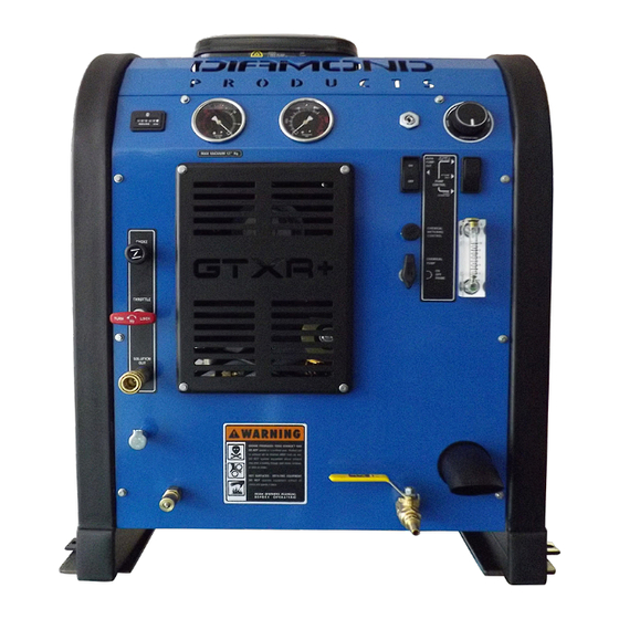
GTXR+
Owner's Manual
HydraMaster
11015 47
Avenue West
th
Mukilteo, Washington 98275
MAN-47281 Rev. C, MAY, 2018
(P/N 000-182-740D)
No part of this manual may be reproduced or used in any form or by any means (i.e. graphic, electronic, photocopying or electronic
retrieval systems) without the express written permission of HydraMaster. Specifications and information in this document are
subject to change without prior notice. All rights reserved. © 2015 HydraMaster
Advertisement
Table of Contents

Related Manuals for HydraMaster GTXR+


Summary of Contents for HydraMaster GTXR+
- Page 1 No part of this manual may be reproduced or used in any form or by any means (i.e. graphic, electronic, photocopying or electronic retrieval systems) without the express written permission of HydraMaster. Specifications and information in this document are subject to change without prior notice. All rights reserved. © 2015 HydraMaster...
-
Page 2: Table Of Contents
Table of Contents GENERAL INFORMATION ................SECTION 1 Major System Components ..............1-3 Contact Information ................. 1-4 Warnings, Cautions and Notices ............. 1-5 Responsibilities ..................1-9 Machine Specifications ................1-12 High Altitude Operation ................1-14 Local Water Precautions ................. 1-14 INSTALLATION INFORMATION .............. - Page 3 SYSTEMS TROUBLESHOOTING ............... SECTION 8 Heating System ..................8-2 Chemical System ..................8-3 Engine ..................... 8-4 High Pressure System ................8-8 Vacuum System ..................8-10 ASSEMBLIES AND PARTS LISTS ............... SECTION 9 Console Assembly Parts List..............9-9 Frame Assembly Parts List ..............9-11 Blower Assembly Parts List ..............
- Page 4 Hard Water Deposits ................11-2 Warranty Procedure ................11-2 ACCESSORIES AND CHEMICAL SOLUTIONS .......... SECTION 12 iii - GTXR + Owner’s Manual...
- Page 5 List of Figures Figure 1-1. Hard Water Map of Mainland United States ..........1-15 Figure 2-1. Location of Roof Vents in Vehicle ..............2-1 Figure 2-2. Recommended Location of GTXR+ in Van ..........2-3 Figure 2-3. Install Fuel Pump, Outlet Side Up ..............2-6 Figure 2-4.
- Page 6 Figure 9-1. Adhesive/Sealant Material Reference ............9-2 Figure 9-2. Console Assembly - View 1 of 6 .............9-3 Figure 9-3. Console Assembly - View 2 of 6 .............9-4 Figure 9-4. Console Assembly - View 3 of 6 .............9-5 Figure 9-5. Console Assembly - View 4 of 6 .............9-6 Figure 9-6.
-
Page 7: General Information
1 - General Information The GTXR + is the latest multi surface cleaning/water recovery system from HydraMaster, featuring a 23 HP air-cooled engine and the dual oil bath Tuthill Dominator 4005 Tri-lobe Blower. Standard equipment for the GTXR + include a 70 gallon recovery tank, 70 gallon rotomolded fresh water tank (FWT), Evolution Truckmount Wand, and a 5 gallon chemical jug. - Page 8 This Owner’s Manual contains installation and operation instructions as well as information required for proper maintenance, adjustment and repair of the GTXR +. Component troubleshooting guides have also been included for your convenience. It is the purpose of this manual to help you properly understand, maintain and service your GTXR +.
-
Page 9: Major System Components
MAJOR SYSTEM COMPONENTS WATER BOX ENGINE HEAT EXCHANGER HEAT EXCHANGER BLOWER PUMP SILENCER 1-3: General Information... -
Page 10: Contact Information
To find a local distributor, please visit our website at http://hydramaster.com/HowToBuy/DealerLocator.aspx If your question cannot be resolved by your distributor or by the information within this manual, you may contact HydraMaster direct using the following phone numbers. HOURS TELEPHONE NUMBERS... -
Page 11: Warnings, Cautions And Notices
WARNINGS, CAUTIONS AND NOTICES HydraMaster uses this WARNING symbol throughout the manual to warn of possible injury or death. This CAUTION symbol is used to warn of possible equipment damage. This NOTICE symbol indicates that federal or state regulatory laws may apply, and also emphasizes supplemental information. - Page 12 Transporting a vented fuel container that presently contains, or has ever contained in the past, a flammable liquid is strictly forbidden by HydraMaster and by federal and state regulations. Doing so will increase the risk of fire and explosion. Serious injury or death may result.
- Page 13 Never smoke in or around the truckmount. Doing so will increase the risk of fire and explosion. Serious injury or death may result. During the operation of the truckmount the exhaust system will become extremely hot. Keep all flammable materials away from the truckmount exhaust system. Failure to do so will increase the risk of fire and explosion.
- Page 14 Never allow water to freeze inside the truckmount. Serious component damage will occur. Perform all freeze guarding procedures outlined in this digital Owner’s Manual. Many vehicles have critical components mounted directly below the floor that can easily be damaged. Before drilling holes in the floor of the vehicle inspect the underside of the vehicle for critical components.
-
Page 15: Responsibilities
RESPONSIBILITIES Purchaser’s Responsibilities • Prior to purchasing a van, ensure that the payload is suitable for all of the equipment that will be installed and transported. This includes and is not limited to: the truckmount, recovery tanks, fresh water tanks and any other on-board water hose reels, hoses, cleaning tools, chemicals and drying equipment. - Page 16 • Ensure proper connection of the fuel lines. • Ensure proper connection and installation of the battery. Verify that the battery is in accordance with HydraMaster’s recommendation. • Check the pump, vacuum blower and engine oil levels prior to starting the truckmount.
- Page 17 Training The distributor should provide a thorough review of the operation manual with the purchaser along with instruction and familiarization in: How all the truckmount’s systems function. All safety precautions and their importance. How to correctly start and shut down the truckmount. How to correctly clean with the truckmount.
-
Page 18: Machine Specifications
MACHINE SPECIFICATIONS Frame Dimensions 24”W x 31”H x 36”D Weight 563 lbs Engine 23HP Briggs and Stratton air- cooled Pressurized Oil System Engine Oil: 5W-30 Synthetic Capacity Approx. 1 1/2 quarts, or 48 oz (when changing oil and filter) Engine rpm 3,000 rpm Fuel Consumption 1.1 gph... - Page 19 Standard Equipment Runtime Hour Meter Chemical Flow Meter (0-10 Gph) Chemical Flow Control Valve Vacuum Gauge (0-30" Hg) Solution Pressure Gauge (0 - 1,500 Psi) Solution Pressure Adjustment Pre-Wired Pump-In Switch Pre-Wired Pump Out Switch Fresh Water Inlet Water System Drain Valve Diagnostic/Status Lights Engine Choke Engine Throttle...
-
Page 20: High Altitude Operation
Hard Water Advisory HydraMaster recognizes that any hard water deposits which might occur within the water system of our truckmounts is a serious problem. The precision technology of truckmount heat exchanger systems is intolerant of any foreign material. Hard water deposits will ultimately decrease the performance of the system and are expected to seriously lower the reliability of the machine. - Page 21 Hard Water Area Map The hard water map, shown in Figure 1-1, defines hard water areas in the continental United States which compromise fluid related components such as hoses, fittings, heaters, pumps, valves and water-cooled engines. For other countries, hard water area maps can be obtained from geological societies.
- Page 22 Cleaning efficiency and equipment life is increased, chemical use decreased, and the appearance of cleaned carpets enhanced when water softeners are incorporated in hard water areas. HydraMaster strongly urges the use of water softener units with the in areas exceeding 3.0 grains per gallon.
- Page 23 HydraMaster makes an automatic pump-out system, called AWDS, which can be ordered with new equipment or installed later. When properly configured, the systems will continuously monitor the level of waste water and pump it out simultaneously with the cleaning operation.
-
Page 24: Installation Information
3/4 HD ton capacity. If a fresh water tank is added, a one ton or larger capacity van is required. Prior to installation of the GTXR +, HydraMaster recommends installing a spray-on bed liner in the vehicle. This provides ‘metal to cushion’ mounting rather than ‘metal to metal’... -
Page 25: Operating The Gtxr+ In Hot Weather
OPERATING THEGTXR + IN HOT WEATHER HydraMaster recommends the following steps when operating the GTXR + during periods of hot weather (95º F or higher). This will help ensure that your GTXR + continues to run at 100% capacity during even the hottest days. - Page 26 Use caution when drilling any holes through the van floor. Many vans have critical components mounted directly below the vehicle floor that could be damaged by a misplaced drill bit. LOCATING THE GTXR + IN VEHICLE There are two recommended entry points on the vehicle for the GTXR + installation: the side door or the rear doors.
- Page 27 Protect yourself and the machine. HydraMaster strongly recommends that the exhaust from the front of the machine be vented down under the truck to prevent carbon monoxide from entering the job site.
-
Page 28: Setting Up The Gtxr
SETTING UP THE GTXR + Prior to operating the GTXR +, follow these steps: Adjust the vacuum relief located on the recovery tank by capping all the vacuum inlets. The machine should be set to 14” Hg maximum. Setting the vacuum level higher than the recommended value can result in an increased risk of serious component damage. -
Page 29: Orientation Of Fuel Pump
ORIENTATION OF FUEL PUMP For proper fuel pump operation and fuel flow, the vehicle’s fuel pump must be installed in a lower position with respect to the fuel tank and in as vertical a position as possible (outlet side up - see Figure 2-3 and Figure 2-4). -
Page 30: Cleaning And Chemicals
HydraMaster’s ClearWater Rinse™ has been formulated to protect vital components. HydraMaster will not warranty parts that have been damaged from using acid products that have obviously caused failures. 3-1: Cleaning Information... -
Page 31: Preparing The Carpet For Extraction
Relying on the rinse detergent to do the majority of the cleaning will result in overly long dry times and excess detergent residue left in the carpet. HydraMaster recommends the use of our pre-sprays: Fastbreak™ for residential carpet and Blitz™ for commercial carpet needs. -
Page 32: Overwetting
For more information about HydraMaster’s complete chemical product line, visit this webpage: https://HydraMaster.com/Chemicals. OVERWETTING Overwetting is an annoyance to all concerned. Extended drying times will leave the customer with a negative impression of both the cleaning company and the process used. -
Page 33: Cleaning Tool Tips
CLEANING TOOL TIPS Wands With a wand, keep cleaning strokes short, front to back, and run a “dry pass”. After pulling the wand for a strip of 3 or 4 ft long with the solution trigger activated, go back up to the top of the stroke, and make a “dry “ pass [i.e. no solution flowing]. This gives the wand a second chance to pick up the solution on the carpet. - Page 34 3-5: Cleaning Information...
- Page 35 Cleaning Information: 3-6...
- Page 36 Rotary Tools HydraMaster’s selection of Rotary Extraction Tools includes the RX-15H and the RX-20 ® RX-15H Hard Surface Cleaning Tool The RX-15H can be used to clean tile, concrete and stone floors. Select the appropriate pre-spray and apply to the floor.
- Page 37 RX-20 Tool for Carpet, Hard Surface and Bonnet Cleaning Before turning on the RX-20, adjust the handle; it should rest right below or even with the bottom of your pants’ front pockets, with the tool resting flat on the floor. Take your time in adjusting the tool’s height;...
- Page 38 Upholstery Tool - DriMaster 3 Use the upholstery tool on small rugs and furniture. When you clean rugs, be sure that the temperature and chemicals are safe for that particular type of rug. As with the larger tools, do not leave the surface of the upholstery too wet. Adjust the volume of water on the tool without it touching any surface: the water should just barely come out of the tool before the vacuum pulls it back in.
- Page 39 Cleaning Information: 3-10...
-
Page 40: Operating Instructions
4 - Operating Instructions Ignition Switch Pressure Vacuum Gauge Gauge Temperature Control Dial Hour Meter Auto Pump-Out Switch Pump-In/Pump Clutch Switch Choke Throttle Figure 8-1. GTXR + Upper Dash Assembly This section describes how to operate the GTXR +, starting with a description of the dash assembly (see Figure 4-1). - Page 41 Chemical System Solution Blower Lube Port Incoming Fresh Water Water Box Drain The lower dash houses the controls for: Figure 8-2. GTXR + Lower Dash Assembly • Water pressure • Chemical system • Water box drain The lower dash assembly also houses the blower lube port and the solution out port where the wand/tool connects to the GTXR + (see Figure 4-2).
-
Page 42: Start Up Procedure
the IDLE throttle position. To do so will increase the risk of serious component or engine damage. START UP PROCEDURE Perform all daily periodic maintenance as specified in this Owner’s Manual. Connect a garden hose to supply water to the truckmount (see Figure 4-2). If the Pump-In feature is used on your system, push the “PUMP-IN SYSTEM”... - Page 43 Allow the chemical to flow through the CHEMICAL METER at full flow for 30 seconds. Turn the “CHEMICAL SYSTEM” valve to “ON.” The restriction can now be Chemical Metering Control Knob Chemical Meter Chemical System Valve Figure 8-3. GTXR + Chemical System Control and Metering removed from the vacuum inlet.
-
Page 44: Shut Down Procedure
Cap off the inlet(s) to the recovery tank. Spray a HydraMaster-recommended spray lubricant into the “BLOWER LUBE PORT” for about 5 to 7 seconds while the unit is running (see Figure 4-2). Allow machine to run additional 2 to 5 minutes under load to flush off lubricant. - Page 45 Operating Instructions: 4-6...
-
Page 46: Machine Maintenance
A maintenance log, provided in the Owner’s Guide, must be correctly and completely filled out. HydraMaster may request to inspect the logs before a warranty claim is honored. It is recommended that the log be affixed to the vehicle door near the truckmount for convenience and to serve as a maintenance reminder. -
Page 47: Operational Maintenance
• Inspect the truckmount for water and oil leaks, loose electrical connections, etc. and repair as needed. • Lubricate the blower lube port with a HydraMaster-recommended lubricant. Weekly Maintenance • Inspect the recovery tank filters for tears, holes, etc. Repair or replace as needed. - Page 48 • Change the blower oil after first 100 hours of use. 250 Hours • Check coupler element (rubber insert) for cracks or wear. Replace as necessary. • Check valve clearance, intake and exhaust 0.004 to 0.006” every 250 hours. 500 Hours •...
-
Page 49: Overall Machine Maintenance
OVERALL MACHINE MAINTENANCE Maintenance, troubleshooting and repair are much easier tasks to accomplish on a clean truckmount. Regular cleaning of the truckmount offers the user an opportunity to visually inspect all facets of the truckmount and spot potential problems before they occur. In addition to the operational maintenance the following “housekeeping”... -
Page 50: Engine Maintenance
ENGINE MAINTENANCE Engine Oil Level Check The engine oil level should be checked daily. It is recommended that the oil be checked just before the engine is started for the first time for that day. The oil level should be between the ‘Add’... - Page 51 Oil Filter Briggs and Stratton engines use Briggs and Stratton oil filters. An equivalent or better oil filter must be used when servicing the engine. To replace the filter, use a proper filter wrench to remove the filter. Clean the filter mounting base and lightly coat the gasket surface of the new filter with engine oil.
-
Page 52: High Pressure Pump Maintenance
HIGH PRESSURE PUMP MAINTENANCE Daily Check the oil level and the condition of the oil. The oil level should be up to the center of the sight glass on the side or rear of the pump or between the “MIN” and “MAX” lines on the dipstick. - Page 53 Servicing Valves on the High Pressure Pump Removing a Valve Remove the valve cap (30 mm) and extract the valve assembly (see Figure 5-1). Figure 8-1. Remove Valve Cap and Valve Assembly Remove the valve assembly (retainer, spring, valve plate, valve seat) from the valve cavity.
- Page 54 Replace center inlet check valve with modified check valve - Figure 5-3. Modified Check Valve Figure 8-3. Replace Center Inlet Check Valve With Modified Check Valve Apply O-ring grease to O-rings and install valves (Figure 5-4). Replace valve cap and torque to 95 ft lbs see Figure 5-5). Figure 8-4.
- Page 55 10. Remove the fasteners retaining the manifold Separate manifold from crankcase (see Figure 5-6). Figure 8-6. Separate Manifold from Crankcase It may be necessary to rotate crankshaft or tap manifold with rawhide or plastic mallet to loosen. When sliding manifold from crankcase, use caution not to damage ceramic plungers.
- Page 56 15. Remove the stainless steel plunger bolt and ceramic plunger from the plunger guide (see Figure 5-9). 16. If the slinger washer is removed, be certain it is re-installed or replaced. 17. Separate plunger bolt from ceramic plunger (see Figure 5-9). Figure 8-9.
- Page 57 Extracting Seals With manifold removed from crankcase: Insert proper extractor collet through main seal retainer (see Figure 5-11). Tighten collet and extract retainers and seals. The Teflon seals of the HT series will be damaged during disassembly so new ones with have to be installed. Figure 8-11.
- Page 58 Replacing the Seal Assemblies Only one seal kit is necessary to repair all the seals in the pump (see Figure 5-12). Use an insertion tool for seal installation Figure 8-12. Seal Kit and Insertion Tool for Seal Installation To install a seal assembly: 1.
- Page 59 To install the intermediate retainers and the low pressure seals: Insert the brass intermediate retainer into the cavity. Press the new low pressure seal into the brass low pressure seal retainer and install a new O-ring on the outside (see Figure 5-14). Figure 8-14.
- Page 60 Re-Installing Manifold Position the outer plungers at the same position (see Figure 5-16). Re-install manifold and torque the fasteners in an “X” pattern to 50% of specification and then retorque to 100% specification (see Figure 5-17 and Figure 5-18). Figure 8-16. Re-install Manifold and Torque Fasteners Figure 8-17.
-
Page 61: Vacuum System Maintenance
Cap off the inlet(s) to the vacuum tank. Spray a HydraMaster-recommended spray lubricant into the “BLOWER LUBE PORT” for about 5 to 7 seconds while the unit is running. Uncap the inlet(s) and run the unit for another minute to allow the blower to cool down. -
Page 62: Descaling Procedure (Required)
DESCALING PROCEDURE (REQUIRED) Scale deposits on the interior of the heating system can cause a noticeable loss in heating performance. Deposits of this kind result from hard water. The frequency with which descaling procedures are required will vary. If the area has particularly hard water, you may have to descale often. -
Page 63: Freeze Guarding
FREEZE GUARDING To avoid permanent damage to the truckmount, it is imperative to follow the Freeze Guard Procedure whenever the possibility of freezing temperatures exists. When disposing of antifreeze, follow local laws and regulations. Do not discard into storm sewers, septic systems or onto the ground. Antifreeze is harmful or fatal if swallowed. - Page 64 Freeze Guard Procedure With the truckmount turned off and the incoming water line disconnected, open the water box drain valve on the front of the truckmount. Allow the system to fully drain. Add 2 gallons of 50/50 antifreeze and water mix to the water box. Attach a section of solution hose to the outgoing solution fitting on the front of the machine.
- Page 65 To freeze guard the hoses and wand, perform the preceding procedure with the items to be freeze guarded attached. Always check the freezing level of your reclaimed antifreeze with a glycol tester before reusing. Failure to do so may result in serious component damage. Recovering Antifreeze for Re-Use Attach all hoses and wands which have been freeze guarded to the truckmount.
-
Page 66: Water And Chemical System
6 - Water and Chemical System This section describes the GTXR +’ water and chemical systems, and includes the exhaust subsystem. The process starts when fresh water is brought through the front of the truckmount into the water box, as indicated in Figure 6-1. The level of water in the box is maintained by the use of a float valve. - Page 67 Finally, the water joins the chemical where the solution is created (see Figure 6-2). The chemical is pressurized by the HydraMaster diaphragm chemical pump attached to the head of the water pump. This pump pulls the chemical from the chemical, or soap, jug through the chemical flow meter (see Figure 6-3).
- Page 68 Figure 8-1. Flow Diagram - View 1 of 3 000-179-038 Rev. D 6-3: Water and Chemical System...
- Page 69 Figure 8-2. Flow Diagram - View 2 of 3 000-179-038 Rev. D Water and Chemical System: 6-4...
- Page 70 Figure 8-3. Flow Diagram - View 3 of 3 000-179-038 Rev. D 6-5: Water and Chemical System...
-
Page 71: Electrical System
7 - Electrical System This section describes how the electrical system functions in the following manner: „ Electrical System Information „ Electrical Schematic „ Wiring Diagram ELECTRICAL SYSTEM INFORMATION The GTXR + electrical system operates on 12 V DC which is provided by the battery. Battery levels are maintained by a 20 Amp alternator mounted on the engine. - Page 72 Figure 8-1. Electrical Schematic 000-179-048 Rev. B Electrical System: 7-2...
- Page 73 7-3: Electrical System...
- Page 74 COLOR KEY Figure 8-2. Wiring BLACK - DENOTES WIRES Diagram - View 1 of 2 RED - DENOTES OPTIONAL EQUIPMENT 000-179-047 Rev. C GREEN - DENOTES COMPONENTS THERMOSTAT IGNITION SWITCH TS-1 [TO ENGINE GROUND] 17(WHT/ORG) SW-1 20(BLK/WHT) HOUR METER HI-1 38(BLU/WHT) 20(BLK/WHT) 24(PNK)
- Page 75 Figure 8-3. Wiring Diagram - 23(PNK/WHT) 23(PNK/WHT) 25(PNK) [TO IGNITION SWITCH SW-1 #2] 03(YEL) View 2 of 2 P-10 J-10 (ORG) 35(ORG) [TO IGNITION SW-1 #5 - 16 GA.] 000-179-047 Rev. C FUSE FUSE 06(ORG) 14 GA FU-1 FU-1 19(BLK) P-11 J-11 P-13...
-
Page 76: Systems Troubleshooting
8 - Systems Troubleshooting This section describes the standard troubleshooting procedures in the following areas: „ Heating System „ Chemical System „ Engine „ High Pressure System „ Vacuum System 8-1: Systems Troubleshooting... -
Page 77: Heating System
HEATING SYSTEM 1.0 Truckmount overheats and shuts down Possible Cause Solution 1.1 The orifice or filter screen Remove and inspect. Clean as necessary. is restricted. 1.2 The dump solenoid is Inspect the solenoid and the hose that delivers restricted. water to it. Clean or replace as necessary. 1.3 The dump solenoid is Check the main fuse. -
Page 78: Chemical System
CHEMICAL SYSTEM 1.0 System will not prime Possible Cause Solution 1.1 The check valves in Remove the valves and inspect. Clean or replace as chemical pump are faulty. necessary. 1.2 The chemical pump Remove and inspect. Replace as necessary. diaphragm is faulty. 1.3 The check valve in high Remove the valve and inspect. -
Page 79: Engine
ENGINE 1.0 Will not turn over Possible Cause Solution 1.1 A loose or corroded Clean and tighten the battery terminal connections. battery terminal. 1.2 The battery is dead. Recharge or replace the battery. Test the charging system. Repair if necessary. Do not attempt to jump start the truckmount from a running vehicle. - Page 80 2.0 Turns over but will not start; there is no spark. (To check for spark, refer to engine manual.) Possible Cause Solution 2.1 The recovery tank is full. Drain the tank. 2.2 The recovery tank float is Inspect the float. Repair or replace as necessary. faulty.
- Page 81 4.0 Will not come up to normal operating rpm. Note: engine should be adjusted to run at 3,200 rpm under no vacuum load. Possible Cause Solution 4.1 The throttle linkage is out Inspect for broken or loose linkage. Repair or replace of adjustment.
- Page 82 7.0 Engine overheats Possible Cause Solution 7.1 Poor ventilation in the van. Open all the van doors. Install a roof vent in the van. Remove any dividers or other objects impeding airflow around the truckmount. 7.2 Low oil level. Check the level and fill as necessary. Running the engine with a low oil level can cause severe damage to the engine.
-
Page 83: High Pressure System
HIGH PRESSURE SYSTEM 1.0 The pump will not come up to normal cleaning pressure Possible Cause Solution 1.1 The pressure adjusting Inspect the valve. Repair or replace if necessary. valve is faulty. 1.2 Worn seals or valves in Test the pump output volume directly from the pump the pump. - Page 84 4.0 Pressure pulsation Possible Cause Solution 4.1 Air leak between the water Check all the hoses and fittings for cuts, breaks, box and pump. cracks, etc. Repair as necessary. 4.2 The check valve(s) in the Remove each valve and inspect for correct pump are faulty.
-
Page 85: Vacuum System
VACUUM SYSTEM 1.0 A weak vacuum at wand. The gauge reads normal. Possible Cause Solution 1.1 Blockage in the hoses or Disconnect the hoses and check for an obstruction. wand tube 1.2 Excessive length of Do not attach excessive lengths of hose. hose connected to the truckmount 2.0 A weak vacuum... - Page 86 5.0 The vacuum blower is locked and will not turn Possible Cause Solution 5.1 Truckmount has been Spray penetrating oil into the blower and let sit for inactive for a period of at least 1 hour. Then very carefully use pipe wrench time and the blower was on the outer diameter of the pulley on the coupler not properly lubricated...
- Page 87 Systems Troubleshooting: 8-12...
-
Page 88: Assemblies And Parts Lists
9 - Assemblies and Parts Lists This section of the manual provides detailed illustrations and parts lists for the following assemblies. When ordering parts for assemblies, first refer to the appropriate assembly listed here and then find the part number listed on that specific page. In most cases, you do not have to order the entire assembly to get a part. - Page 89 HydraMaster equipment. Refer to Figure 9-1 to identify those substances such as A1, A2 and so forth. Equivalent products are acceptable if they meet or exceed current specifications and are approved by HydraMaster. Figure 8-1. Adhesive/Sealant Material Reference...
- Page 90 Figure 8-2. Console Assembly - View 1 of 6 REVISION DESCRIPTION CODE DATE 610-050-754 Rev. A RELEASE DRAWING. 02/14/2018 WASHER, #10 LOCK S. STE WASHER, #10 FLAT S. STE SCREW, #10-24UNC x 0.50" LG. HEX HEAD S. STE RIVET, AB4-3A ALUMINUM POP 1/8" x 1/4" LG. (GRIP RANGE 0.126"- ALUMIN 0.187") PLATE, MACHINE SERIAL I.D.
- Page 91 Figure 8-3. Console Assembly - View 2 of 6 610-050-754 Rev. A 9-4: Assemblies and Parts Lists...
- Page 92 Figure 8-4. Console Assembly - View 3 of 6 610-050-754 Rev. A PART OF FRAME HIDDEN PART OF FRAME HIDDEN FOR CLARITY 9-5: Assemblies and Parts Lists...
- Page 93 Figure 8-5. Console Assembly - View 4 of 6 610-050-754 Rev. A PART OF FRAME HIDDEN FOR CLARITY 9-6: Assemblies and Parts Lists...
- Page 94 Figure 8-6. Console Assembly - View 5 of 6 610-050-754 Rev. A 3.126 35.125 9-7: Assemblies and Parts Lists...
- Page 95 Figure 8-7. Console Assembly - View 6 of 6 610-050-754 Rev. A 3.126 24.000 31.937 30.940 28.000 9-8: Assemblies and Parts Lists...
-
Page 96: Console Assembly Parts List
Console Assembly Parts List Item Part Number Description Item Part Number Description 610-007-737 ASSEMBLY, PUMP 000-068-203 HOSE, 3/16” I.D. TEFLON x 34” LG. 610-002-754 ASSEMBLY, BLOWER (ORIFICE ASSY TO WB) 610-018-754 ASSEMBLY, DASH - GTXR PLUS 610-004-728 ASSEMBLY, ENGINE 000-068-627 HOSE, 3/16”... - Page 97 REVISIONS REVISION CODE DATE CHKD APPVD REMOVED & NOTATED 081-408 & 081-327; 11/15/2013 S.M.W. C.I.R. ECRB ECR #2464 UPDATED NOTE 1; 055-195 WAS REVISED E MOVED 105-012 & 140-001 TO CONSOLE. ECR #2520 05/15/2014 L.O.L. C.I.R. ECRB Figure 8-8. Frame Assembly - View 1 of 2 610-001-729 Rev.
-
Page 98: Frame Assembly Parts List
Figure 8-9. Frame Assembly - View 2 of 2 610-001-729 Rev. E 000-081-327 LABEL, ANSI WARNING TEXT ONLY P/N 000-081-327 and 000-081-408 are part of label set P/N 000-081-039. Only label sets can be sold; individual labels not available for sale. Frame Assembly Parts List Item Part Number Description... - Page 99 Figure 8-10. Blower Assembly - View 1 of 2 610-002-754 Rev. B See Figure 9-1 for adhesive/sealant information. REVISION DESCRIPTION CODE DATE CHKD APPVD RELEASE DRAWING 2/9/2018 M.B.B. L.O.L. M.B.B. ADD 174-057. 174-004 QTY WAS 18 03/12/2018 M.B.B. L.O.L. L.O.L. BETA REUSE MAGNETIC PLUG (REMOVED TO INSTALL...
- Page 100 40 FT LBS Figure 8-11. Blower Assembly - View 2 of 2 000-027-112 610-002-754 Rev. A CAP, OIL SIGHT GLASS WASHE BLOWER See Figure 9-1 for sealant information. WASHE WASHE TORQUE TO 40 FT LBS SCREW SCREW SCREW SCREW PLUG, NUT, 3 KEY, 3 INSER...
-
Page 101: Blower Assembly Parts List
Blower Assembly Parts List Item Part Number Description Item Part Number Description 000-001-071 ADAPTER BLOWER INLET - COATED 000-077-011 KEY, 3/16” X 1 1/2” LONG 000-001-871 ADAPTER BLOWER OUTLET 2.5 - COATED 000-094-015 NUT, 3/8”-16UNC HEX 2 WAY LOCKING 000-111-145 BLOWER, 4005 DOMINATOR 000-106-001 PLUG, 1/8”... -
Page 102: Silencer Assembly Parts List
Silencer Assembly Parts List Figure 8-12. Silencer Assembly Item Part Number Description 610-021-724 Rev. B 000-033-012 CLAMP, SIZE #44 HOSE 000-068-104 HOSE, Ø2.5” ID x 2.5” LG. 000-093-108 SILENCER, Ø2.5” OD INLET/OUTLET - COATED 9-15: Assemblies and Parts Lists... - Page 103 Figure 8-13. Engine Assembly - View 1 of 2 610-004-728 Rev. E See Figure 9-1 for adhesive/sealant information. 9-16: Assemblies and Parts Lists...
-
Page 104: Engine Assembly Parts List
Engine Assembly Parts List Figure 8-14. Engine Assembly - View 2 of 2 610-004-728 Rev. E Item Part Number Description 000-020-025 Bushing, H X 1” 000-033-117 Clamp, 1” Cushion Loop w/ 7/16 Mount Hole 000-039-054 Coupler, 40 Series 000-047-037 Engine, 23HP 000-049-258 Filter, Fuel (Comes w/ Engine) 000-057-026... - Page 105 Figure 8-15. Pump Assembly 610-007-737 Rev. B See Figure 9-1 for adhesive/sealant information. 9-18: Assemblies and Parts Lists...
-
Page 106: Pump Assembly Parts List
Pump Assembly Parts List Item Part Number Description Item Part Number Description 000-001-096 ADAPTER, CHEM. PUMP TO COMET 000-094-038 NUT, 5/16”-18UNC HEX NYLOCK 610-009-747 ASSEMBLY, BY-PASS VALVE - CTS 400 FLEX 000-097-057 O-RING, ADAPTER - CHEMICAL PUMP 000-036-008 CLUTCH, 7” O.D. 24mm SINGLE GROOVE 000-105-148 PLATE, CLUTCH MOUNT COMET PUMP 000-052-084... - Page 107 Figure 8-16. Blower Heat Exchanger Assembly - View 1 of 2 REVISION DESCR 610-005-754 Rev. A RELEASE DRAWING. SENSOR (COMES WITH 000-149-025) See Figure 9-1 for sealant information. 9-20: Assemblies and Parts Lists TEE, 3/8" NPT MALE STREET SENSOR, 285F NASON- 3/8" NP SCREW, #10-24UNC x 0.50"...
-
Page 108: Blower Heat Exchanger Assembly Parts List
Blower Heat Exchanger Assembly Parts List SENSOR (COMES WITH 000-149-025) Item Part Number Description Item Part Number Description 000-057-255 GASKET, SALSA HX - CDS ZR-2017 000-052-738 ADAPTER, 1/4” NPT x 1/2” FPT 000-052-528 NIPPLE, 3/8” M JIC x 3/8” NPT 000-013-115 BOX, OUTLET PLENUM, STEEL - COATED 000-052-128... - Page 109 WAS 159-107, ADDED 174-05 Figure 8-18. Water Box Assembly - View 1 of 2 610-010-729 Rev. C See Figure 9-1 for adhesive and sealant information. WASHER, 7/8 WASHER, 3/8 WASHER, 1.5 WASHER, 3/8 TEE, 3/8" NPT TEE, 1/4" PLA TANK, POLY W SWITCH, w/PR SCREW, 3/8"- SCREW, #8 x...
-
Page 110: Water Box Assembly Parts List
Water Box Assembly Parts List Item Part Number Description Item Part Number Description 000-169-235 ASSEMBLY, ROBERT FLOAT VALVE 000-143-314 SCREW, #8 x 1/2” LG. PAN HEAD REVISION DESCRIPTION CODE DATE CHKD APPVD REVISION DESCRIPTION CODE DATE CHKD APPVD 000-052-660 BULKHEAD, 3/8” FPT x 3/8” FPT 000-143-017-1 SCREW, 3/8”-16UNC x 0.75”... - Page 111 Figure 8-20. Dash Assembly - View 1 of 2 610-018-754 Rev. A See Figure 9-1 for adhesive/sealant information. 9-24: Assemblies and Parts Lists...
- Page 112 Figure 8-21. Dash Assembly - View 2 of 2 610-018-754 Rev. A 9-25: Assemblies and Parts Lists...
-
Page 113: Dash Assembly Parts List
GAUGE, PRESSURE 0 -1500 PSI, UPC #401406. 000-157-131 SWITCH, 3 WAY SPEED CONTROL 000-052-090 TEE, 1/4” NPT BRANCH M-F-F 000-074-017 GAUGE, 30” HG. VACUUM - HYDRAMASTER 000-149-025 THERMOSTAT, BULB & CAPILLARY 000-052-099 INSERT, #26 (1/8” NPT x 3/8” BARB) 000-131-131 TRIMLOK, 3/8”... -
Page 114: Differential Check Valve Assembly Parts List
Figure 8-22. Differential Check Valve Assembly 000-169-236 Rev. B Differential Check Valve Assembly Parts List Item Part Number Description Item Part Number Description 000-097-054 O-Ring, Chem. Pump Valve Viton-Parker 2-114 000-005-012 Ball, 0.500 Dia Stainless Steel 000-107-258 Body, Differential Check Valve 000-148-012 Seat, Differential Check Valve 000-106-180... - Page 115 Figure 8-23. By-Pass Valve Assembly - View 1 of 2 610-009-747 Rev. C See Figure 9-1 for sealant information. 9-28: Assemblies and Parts Lists...
-
Page 116: By-Pass Valve Assembly Parts List
Figure 8-24. By-Pass Valve Assembly - View 2 of 2 610-009-747 Rev. C By-Pass Valve Assembly Parts List Item Part Number Description 000-052-086 ELBOW, 3/8” NPT STREET 000-052-105 INSERT, #68 (3/8” NPT x 1/2” BARB) 000-052-128 NIPPLE, 3/8” MPT x 3/8” SAE FLARE 000-052-074 NIPPLE, 3/8”... - Page 117 Figure 8-25. Hi-PSI Manifold Assembly - View 1 of 2 610-021-729 Rev. - See Figure 9-1 for sealant information. 9-30: Assemblies and Parts Lists...
-
Page 118: Hi-Psi Manifold Assembly Parts List
Figure 8-26. Hi-PSI Manifold Assembly - View 2 of 2 610-021-729 Rev. - Hi-PSI Manifold Assembly Parts List Item Part Number Description 000-052-084 ELBOW, 1/8” NPT STREET 000-049-052 FILTER CARTRIDGE,1/4”BRASS 000-052-153 HOUSING, STABILIZER NOZZLE 000-052-530 NIPPLE, 1/4” SAE x 1/8” NPT 000-052-586 NIPPLE, 1/8”... -
Page 119: Idler Pulley Assembly Parts List
FLIPPED ORIENTATION OF 000-154-128. 1/19/2015 S.M.W. L.R.K. ECRB FLIPPED ORIENTATION OF 000-154-128. ECR #2562 1/19/2015 S.M.W. L.R.K. ECRB REPLACED 000-143-041 WITH 000-143-716. REPLACED 000-143-041 WITH 000-143-716. REPLACED 000-154-128 WITH 000-154-049. ADDED ECR #2635 3/3/2016 C.I.R. ECRB 3 QTY. 000-174-012 WAS 1 AND ADDED NOTE 1. REPLACED 000-154-128 WITH 000-154-049. -
Page 120: Exhaust Assembly Parts List
REVISION DESCRIPTION CODE DATE RELEASE DRAWING 2/9/2018 REVISION DESCRIPTION CODE DATE CHKD APPVD ADD 057-199; DELETE 057-177 & 125-128. LRIP 03/23/2018 RELEASE DRAWING 2/9/2018 L.O.L. M.B.B. M.B.B. ADD 057-199; DELETE 057-177 & 125-128. 03/23/2018 M.B.B. L.O.L. L.O.L. LRIP Figure 8-28. Exhaust Assembly 610-013-754 Rev. - Page 121 Figure 8-29. 70 Gallon Universal Recovery Tank (URT) Assembly 610-003-728 Rev. D The AWDS is optional equipment. The lower float switch is only used when the automatic pump-out system is installed. 9-34: Assemblies and Parts Lists...
-
Page 122: Gallon Universal Recovery Tank (Urt) Assembly Parts List
70 Gallon Universal Recovery Tank (URT) Assembly Parts List Item Part Number Description Item Part Number Description 000-001-134 Adapter, Ø2.5” Tank X 90° Blower Hose - Coated 000-094-113 Nut, 1/4”-20UNC Neoprene Wellnut 610-029-726 Assembly, Cover, 70 Gal URT, Single Vac. 000-094-009 Nut, 1/4”-20UNC Nylock 610-026-724... - Page 123 Figure 8-30. 70 Gallon Universal Recovery Tank (URT) Cover Assembly 610-029-726 Rev. A REVISIONS REVISION CODE DATE CHKD APPVD ADDED NOTE 2. 4/3/2012 E.J.B. C.I.R. C.I.R. NOTES: ITEM NO UNLESS DIMENS BREAK ALL TOLER .XX= .XXX= NOTES: ANGUL ADHERE ITEMS 5 , 6 &...
-
Page 124: Gallon Universal Recovery Tank (Urt) Cover Assembly Parts List
70 Gallon Universal Recovery Tank (URT) Cover Assembly Parts List Item Part Number Description Item Part Number Description 000-041-443 Cover 000-057-203 Gasket, Middle - Recovery Tank Cover 000-052-219 Adapter, 2” NPT X 2” F Slip 000-057-204 Gasket, Side - Recovery Tank - - - Latch, Bungee - Strike (Part of 000-086-008) 000-052-222... - Page 125 Figure 8-31. Vacuum Relief Valve Assembly 610-026-724 Rev. B Vacuum Relief Valve Assembly Parts List Item Part Number Description Item Part Number Description 000-105-332 Plate, Vacuum Relief Valve Mounting - Coated 000-015-182 Bracket, Vacuum Relief Valve - Fabricated 000-027-032 Cap, Spun Vacuum Relief Valve 000-143-198 Screw, 3/8”-16UNC X 4”...
- Page 126 9-39: Assemblies and Parts Lists...
- Page 127 Figure 8-32. 70 Gallon Fresh Water Tank (FWT) Assembly View 1 of 2 000-163-212 Rev. B TO MACHINE FRESH WATER INLET 9-40: Assemblies and Parts Lists...
- Page 128 Figure 8-33. 70 Gallon Fresh Water Tank (FWT) Assembly View 2 of 2 000-163-212 Rev. B REVISION DESCRIPTION CODE DATE RELEASED DRAWING. 9/11/2012 L.O.L REPLACED 1 QTY. 000-041-365 WITH 000-041-892; 09/22/2017 P.E. ECR #2799 ADDED 1 QTY. 000-057-254. WASHER, 5/16" FLAT 18-8 S.
-
Page 129: Gallon Fresh Water Tank (Fwt) Assembly Parts List
70 Gallon Fresh Water Tank (FWT) Assembly Parts List Item Part Number Description Item Part Number Description - - - INSERT, FLOJET PUMP OUT (COMES w/ 000-111-170) 1 000-015-1238 BRACKET, 70 FWT MOUNTING - COATED 000-033-004 CLAMP, SIZE #6 MINI HOSE 000-052-326 NIPPLE, 3/4”... - Page 130 9-43: Assemblies and Parts Lists...
-
Page 131: How To Order Parts
We shall always endeavor to be fair in our evaluation of your warranty claim and shall provide you with a complete analysis of our findings. HydraMaster warranty covers only defective materials and/or workmanship for the periods listed. Diagnostic reimbursement is specifically excluded. - Page 132 How to Order Parts: 10-2...
-
Page 133: Warranty Information
Such causes listed in this section shall constitute abuse or neglect. BLOWER • Failure to lubricate impellers daily with a HydraMaster-recommended lubricant, to lubricate bearings, to maintain proper oil levels, or to use the correct oil grade and viscosity as recommended in blower manual. -
Page 134: Vacuum And Solution Hoses
Warranty coverage is available to you through your local distributor. If you have moved to a new area or have purchased a used machine and need information regarding your local distributor, call HydraMaster at (800) 426-1301 or email us at: techsupport@hydramaster.com. - Page 135 All material must be properly authorized by HydraMaster prior to being returned. When returning, please provide an explanation of the problem and include the serial number of the machine as well as the name of the selling organization. All defective material must be returned to HydraMaster within 60 days of authorization.
- Page 136 12 - Accessories and Chemical Solutions HydraMaster’s machine accessories are the most innovative collection available in the cleaning industry. For example, our RX-20® has changed the shape of steam cleaning. In addition, our hoses, reels and tanks are of the finest quality construction.
- Page 137 Accessories and Chemical Solutions: 12-2...
Need help?
Do you have a question about the GTXR+ and is the answer not in the manual?
Questions and answers