Table of Contents
Advertisement
Quick Links
Advertisement
Table of Contents

Subscribe to Our Youtube Channel
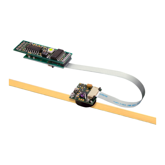
Summary of Contents for Renishaw RGH34
- Page 1 Installation guide M-9537-9024-01-A RGH34 RGS40 linear encoder system...
-
Page 2: Table Of Contents
Contents Product compliance Storage and handling RGH34 readhead installation drawing RGI34 interface installation drawing RGS40 scale installation drawings Scale application End clamps Reference mark and limit switch actuator installation Readhead mounting/installation Readhead set-up Reference mark set-up Limit switch Output signals... -
Page 3: Product Compliance
Product compliance The RGH34 and RGI34 have been designed as system components and to be compliant with EMC The packaging of our products contains the following materials and can be recycled. regulations for products of their type. Care must be taken with shielding and grounding arrangements... -
Page 4: Storage And Handling
Storage Operating Humidity System System +70 °C +55 °C -20 °C 0 °C N-heptane Propan-2-ol Acetone Chlorinated Methylated CHOHCH COCH Solvents Spirits 95% relative humidity (non condensing) to EN 60068-2-78 RGH34 RGS40 installation guide... -
Page 5: Rgh34 Readhead Installation Drawing
RGH34 readhead installation drawing Dimensions and tolerances in mm (Yaw tol. ±1°) (Roll tol. ±1°) Forward direction of 0.09 readhead relative to scale 10.5 Ø12 90° ‘vee’ FPC cable Component area Optical centreline 10.5 2.55 Optional magnetic reference or limit switch sensor -0.1... -
Page 6: Rgi34 Interface Installation Drawing
Bracket omitted from this view Ground connection to case for optimum EMC performance 25.5 (hole dia. 1 mm) 36.5 FPC cable to RGH34 readhead. Available in 50, 100 and 150 mm lengths Mounting bracket Component area (M-9537-0193) supplied with interface 20.5... -
Page 7: Rgs40 Scale Installation Drawings
Overall length (ML + 70) NOTE: The surface roughness of the scale mounting surface must be ≤3.2 Ra. The parallelism of the scale surface to the axis of motion (readhead rideheight variation) must be within 0.05 mm. RGH34 RGS40 installation guide... -
Page 8: Scale Application
The scale applicator A-9537-0197 is used for installing RGS40 scale for RGH34 systems only. Fit end clamps (see ‘End clamps’ section). The RGH34 scale applicator is designed for use with a ‘typical’ RGH34 mounting bracket, for example: Allow 24 hours for complete adhesion of scale before fitting the reference mark or limit magnet. -
Page 9: Readhead Mounting/Installation
Mounting brackets FPC cable insertion The RGH34 is designed to be integrated into OEM products, and as such the recommendations given here The FPC cable connectors on the RGH34 readhead and RGI34 interface are of the ZIF for mounting brackets are intended only as a guide. -
Page 10: Readhead Set-Up
NOTE: Reference mark output is synchronised with the incremental channels, giving unit of resolution pulse width. must be properly connected to the power supply to enable the set-up LED to be used. NOTE: Check that the reference mark sensing option has been specified on the RGH34 and RGI34 that you Confirming set-up have purchased. -
Page 11: Limit Switch
Lowest recommended counter input frequency (MHz) CAUTION: The limit switch feature must never be used as a fail-safe stop device. (10 μm) NOTE: Check that the limit switch sensing option has been specified on the RGH34 Encoder velocity (m/s) (5 μm) and RGI34 that you have purchased. -
Page 12: Electrical Connections
Terminate the inner shield to 0V power at the customer interface 120 Ω • Maximise the distance between encoder and motor cables Remote LED driver outputs The remote LED driver output allows remote monitoring of readhead installation. 150 Ω Green Red/Green Green – RGH34 RGS40 installation guide... -
Page 13: Output Specifications
Actuation device: A-9531-0250 or A-9541-0037 +) - (V -18° 108° Actuation device: A-9531-0250 or A-9531-0037 0° NOTE: RGH34 readheads and RGI34 digital † Limit Asynchronous pulse interfaces are available with reference mark or limit switch detection. Repeatability <0.1 mm typical Select output option at order. -
Page 14: General Specifications
Scale end movement <1 µm over temperature range -20 °C to +50 °C Temperature Operating -10 °C to +120 °C. Minimum installation 10 °C Storage -20 °C to +70 °C. Humidity 95% relative humidity (non-condensing) to EN 60068-2-78 RGH34 RGS40 installation guide... - Page 15 For worldwide contact details, please visit our main website at www.renishaw.com/contact RENISHAW and the probe symbol used in the RENISHAW logo are registered trade marks ® of Renishaw plc in the United Kingdom and other countries. *M-9537-9024-01* apply innovation and names and designations of other Renishaw products and technologies are trade marks of Renishaw plc or its subsidiaries.


Need help?
Do you have a question about the RGH34 and is the answer not in the manual?
Questions and answers