Advertisement
Quick Links
Advertisement

Related Manuals for Minka-Aire Alva F852L


Summary of Contents for Minka-Aire Alva F852L
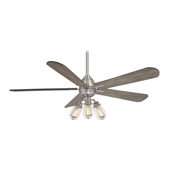
- Page 1 Alva U.S. Patent Pending...
- Page 2 ©2017 Minka Lighting Inc. Manual design and all elements of manual design are protected by United States Federal and/or State Law including Patents, Trademark , and/or Copyright Laws.
- Page 4 F852L...
- Page 5 INSTALLING THE LIGHT KIT...
- Page 7 wattage MR153B TR110BL...
- Page 8 Light shade(3 pcs) Light bulb(3 pcs) Blade bracket Receiver(include 6 wire nuts) hardward 1/4* Hand held remote with 2 screws 11mm+S screw (11pcs) (5 pcs) M3 L wrench 8mm R wrench Blade holder(5 pcs) Light kit assembly Coupler cover...
- Page 10 ATTACHING THE FAN BLADE Step 1: Assemble the blade with blade holders with the provided blade attachment screws. (fig.5) Screw Step 2: Assemble the blade holder onto the fan Washer body. Pay attention to the side up. (fig.6&7) Blade Blade Blade Holder Screw...
- Page 11 hanger ,and slip the coupler cover on to the fan body.
- Page 12 Hanger Downrod ball Downrod Junction Box Coupler Cover Canopy Hanger Bracket B clip Canpler Cover Clevis Pin Fan Body Hanger Coupler Bracket Cover Washer Fan Body Downrod Star Washer Spring Washer Screw Fig.8 Fig.9 Fig.10 Fig.11 Fig.12 Fig.13...
- Page 13 Fig.14...
- Page 14 Motor to Receiver electrical connections: connect the WHITE WIRE from the fan to the WHITE wire from receiver. Connect the RED wire from the fan to the RED wire from the Receiver. Connector the BLUE wire from the fan to the BLUE wire from the recelver. connect the PURPLE wire from the fan to the PURPLE wire from the receiver.
- Page 15 Receiver Canopy Canopy Hanger Bracket Screw Screw Screw Canopy Cover cover Fig.17 Fig.18 Fig.19...
-
Page 16: Installing The Light Kit
INSTALLING THE LIGHT KIT wattage Step 1. Remove the hex screws from fan body with the L wrench.(fig.20) Step 2. Remove the 6 nuts from the light shade assembly. (fig.21) Step 3. Install the bulbs.(Fig.22) Socket Step 4. Re-assemble the light kit shade and tighten Screw the nut with the provided wrench. - Page 18 (CLOCKWISE DIRECTION) (COUNTERCLOCKWISE DIRECTION) Fig.26 Fig.27...
- Page 22 0.07 4.19 2.12 0.45 32.56...
- Page 23 3304.43 4.19 788.64 5 272 7044.91 32.56 216.36 MKA17010701...
Need help?
Do you have a question about the Alva F852L and is the answer not in the manual?
Questions and answers