Table of Contents
Advertisement
Advertisement
Table of Contents

Related Manuals for Minka-Aire TRADITIONAL CONCEPT


Summary of Contents for Minka-Aire TRADITIONAL CONCEPT
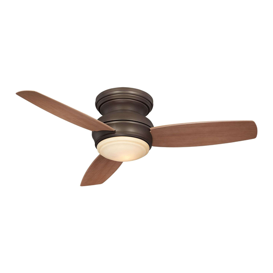
- Page 1 TRADITIONAL CONCEPT INSTRUCTION MANUAL WARRANTY CERTIFICATE...
- Page 2 Manual design and all elements of manual design are protected by U.S. Federal and/or State Law, including Patent, Trademark and/or Copyright laws.
- Page 3 ® return address, and a description of the claimed product defect. Pack carefully; damage sustained in return transit to Minka-Aire will be the original owner's responsibility. Original owner shall be responsible to pay all shipping charges. To obtain warranty service, you may return a fan that proves to be defective during the warranty period to the following address: ®...
- Page 4 This limited warranty is in lieu of all other express warranties. This limited warranty excludes all incidental and consequential damages, and ® Minka-Aire shall not under any circumstances be liable for incidental or consequential damages. Some States do not allow the exclusion of or limitation of incidental or consequential damages, so the foregoing limitation or exclusion may not apply to you.
-
Page 5: Table Of Contents
CONTENTS SAFETY RULES.................... INSTALLING THE LIGHT KIT MOUNTING PLATE ..... PACKAGE CONTENTS................INSTALLING THE LIGHT PLATE............INSTALLING THE MOUNTING BRACKET........INSTALLING THE LIGHT BULB AND GLASS SHADE ..... ELECTRICAL CONNECTIONS.............. OPERATING THE REMOTE CONTROL/WALL CONTROL ..INSTALLING THE WALL TRANSMITTER........CARE OF YOUR FAN................ -
Page 6: Safety Rules
SAFETY RULES 1. Before you begin installing the fan, shut power off at the circuit breaker of the fuse box. 2. Be cautious! Be cautious! Read all instructions and safety information before installing your new fan. Review accompanying assembly diagrams. 3. - Page 7 NOTE: NOTE: The important safeguards and instructions appearing in this manual are not meant to cover all possible conditions and situations that may occur. It must be understood that common sense, caution and care are factors which can not be built into this product. These factors must be supplied by the person(s) installing, caring for and operating the unit.
-
Page 8: Package Contents
PACKAGE CONTENTS Unpack your fan and check the contents. You should have the following items: 1. Fan Blades (3) 11. 100W Mini-Can halogen bulb 12. Balancing kit 2. Mounting bracket 3. Fan motor/housing ass'y 4. Blade support plates (3) A. Mounting hardware: #10 x 1.5"... -
Page 9: Installing The Mounting Bracket
INSTALLING THE MOUNTING BRACKET Tools Required: Phillips screw driver; slotted screw driver; step-ladder; wire cutters; electrical tape. OUTLET BOX WARNING WARNING: All of the parts, hardware and components have been provided for your safety and the proper installation of your new ceiling fan. The use of other parts, hardware or components not supplied by MOUNTING BRACKET ®... -
Page 10: Electrical Connections
ELECTRICAL CONNECTIONS WARNING: WARNING: To avoid possible electrical shock be sure electricity is Step 1 Connect the fan supply (black) wire to the black household supply turned off at the main fuse or breaker box before wiring. wire as shown in Figure 3 & 4. ®... - Page 11 INPUT AC120V OUTLET BOX WHITE (NEUTRAL) BLACK (HOT) WHITE GREEN OR BARE AC SUPPLY COPPER (GROUND) BLACK BLACK ("AC IN L") WHITE ("AC IN N") RECEIVER GROUND BLACK BLACK Fig. 2 Fig. 3 Fig. 4...
-
Page 12: Installing The Wall Transmitter
INSTALLING THE WALL TRANSMITTER WARNING! WARNING! HOOK UP "IN SERIES" ONLY. DO NOT CONNECT NEUTRAL SUPPLY WIRE OF ELECTRIC CIRCUIT TO THE TRANSMITTER WALL SWITCH, DAMAGE TO THE TRANSMITTER WALL SWITCH AND POSSIBLE FIRE COULD OCCUR. Step 1. Remove the existing wall plate and switch from the wall outlet box. Step 2. -
Page 13: Finishing The Installation
FINISHING THE INSTALLATION Step 1. Loosen three of the four screws from the motor and remove the other one. Step 2. Remove the motor assembly from the mounting SCREWS bracket hook and engage the key holes to the three screws previously loosened. -
Page 14: Blade Installation
BLADE INSTALLATION THE FOLLOWING OPERATIONS MUST BE ACCOMPLISHED BEFORE INSTALLING THE LIGHT KIT. THE FOLLOWING OPERATIONS MUST BE ACCOMPLISHED BEFORE INSTALLING THE LIGHT KIT. Insert one fan blade into the blade slot on the motor housing and secure with the screws, rubber washers and blade support plate. -
Page 15: Installing The Light Kit Mounting Plate
INSTALLING THE LIGHT KIT MOUNTING PLATE Step 1. Remove 1 of 3 screws from the mounting ring and loosen the other 2 screws. (Do not (Do not remove) remove) Step 2. Place the key holes from the light kit mounting plate over the 2 screws previously loosened from the mounting ring, turn the light kit mounting plate until it locks in place at the narrow section of the key holes. -
Page 16: Installing The Light Plate
INSTALLING THE LIGHT PLATE NOTE: NOTE: Before starting installation, make sure power is turned off at the circuit breaker. 1. Remove 1 of 3 screws from the light kit mounting plate and loosen the other 2 screws. (Do not (Do not remove) remove) 2. -
Page 17: Installing The Light Bulb And Glass Shade
INSTALLING THE LIGHT BULB AND GLASS SHADE WARNING: WARNING: Shut of the power supply before removing or replacing lamp. In handling of halogen bulb, care should be taken not to touch it with your bare hands. Oil residue will shorten the life of the halogen bulb. If you accidentally come into contact, wipe thoroughly with a clean, lint-free, cotton cloth. -
Page 18: Operating The Remote Control/Wall Control
OPERATING THE REMOTE CONTROL/WALL CONTROL Remote Control only: Install a A23 12 volt battery (included). To prevent damage to transmitter remove the battery if not used for long periods of time. Restore Power to Ceiling Fan. instructions apply to ceiling fans that feature a D. - Page 19 Speed settings for warm or cold weather depend on factors such as room size, ceiling height and number of fans. NOTE: NOTE: To change the direction of the rotation of the blades the fan must be in operation mode. Warm Weather (forward) A DOWNWARD airflow creates a cooling effect as shown in Figure 11.
-
Page 20: Care Of Your Fan
CARE OF YOUR FAN Here are some suggestions to help maintain your fan. 4. Use a lint free lightly damp cloth or duster to remove dust from the blades. 1. Because of the fan's natural movement some connections may become loose. Check the support connections, brackets and blade 5. -
Page 21: Troubleshooting
TROUBLESHOOTING SYMPTOM SYMPTOM SYMPTOM SYMPTOM Fan Sounds Noisy Fan Wobble Fan will not start Fans/Light Turn On and Off Unexpectedly SOLUTION SOLUTION SOLUTION ● SOLUTION Check to make sure the wall switch is ● ● Allow a 24-hour "break in" period. NOTE: NOTE: All blade sets are grouped by turned on. - Page 22 SYMPTOM Frequency Interference SOLUTION 1. Turn the power off to your ceiling fan. 2. Please use a small size tool to change the frequency settings on the control system. 3. Return power to the unit. Note: Note: After the AC power is on, do not press any other button on the transmitter before pressing the "Stop" button, doing so will cause the procedure to fail.
-
Page 23: Specifications
SPECIFICATIONS These are typical readings. Your actual fan may vary. Fan Size Speed Volts Amps Watts N.W. G.W. C.F. They do not include amps and wattage used by the 0.28 13.6 2166.14 light(s). 44" 10.00 2.30’ 8.50 0.37 27.7 3521.38 Medium 0.41 49.4...
Need help?
Do you have a question about the TRADITIONAL CONCEPT and is the answer not in the manual?
Questions and answers