Table of Contents
Advertisement
Advertisement
Table of Contents

Related Manuals for Minka-Aire SPACESAVER


Summary of Contents for Minka-Aire SPACESAVER
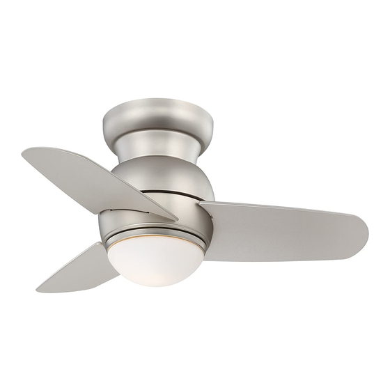
- Page 1 SPACESAVER INSTRUCTION MANUAL WARRANTY CERTIFICATE...
- Page 2 Manual design and all elements of manual design are protected by U.S. Federal and/or State Law, including Patent, Trademark and/or Copyright laws.
- Page 3 ® Minka-Aire warrants to the original owner that this fan will be free from defects in material and workmanship for one ® year from the date of purchase, excluding the motor. Minka-Aire warrants to the original owner that the motor in this fan shall be free from defects in material and workmanship for as long as the original purchaser owns the fan, and it remains in the original installation.
- Page 4 This warranty shall not apply to fans which have been damaged in any way, including improper installation, damage as a result of the removal of the fan from the origial installation, or damage in shipping. This warranty shall not apply to fans which have been subjected to use for which the fan was not designed.
-
Page 5: Table Of Contents
CONTENTS SAFETY RULES..................ATTACHING THE FAN BLADES............PACKAGE CONTENTS..............INSTALLING THE LIGHT KIT MOUNTING PLATE ...... INSTALLING THE FAN..............INSTALLING THE LIGHT PLATE ............HANGING THE FAN................. INSTALLING THE LIGHT BULB & GLASS SHADE ...... ELECTRICAL CONNECTIONS............OPERATING YOUR FAN..............INSTALLING THE WALL CONTROL.. -
Page 6: Safety Rules
SAFETY RULES 1. Before you begin installing the fan, shut power off at the circuit breaker of the fuse box. 2. Be cautious! Read all instructions and safety information before installing your new fan. Review accompanying assembly diagrams. 3. Make sure that all electrical connections comply with local codes, ordinances, or National Electrical Codes. Hire a qualified electrician or consult a do-it-yourself wiring handbook if you are unfamiliar with installing electrical wiring. - Page 7 NOTE: The important safeguards and instructions appearing in this manual are not meant to cover all possible conditions and situations that may occur. It must be understood that common sense, caution and care are factors which can not be built into this product. These factors must be supplied by the person (s) installing, caring for and operating the unit.
-
Page 8: Package Contents
PACKAGE CONTENTS Unpack your fan and check the contents. You should have the following items: 1. Fan blades (3) A. Mounting hardware: 2. Blade support plates (3) #10 x 1.5" Wood screws (2 PCs.) 3. Mounting bracket #8 x 3/4" Machine screws (2 PCs.) 4. -
Page 9: Installing The Fan
INSTALLING THE FAN Tools Required: Phillips screw driver; slotted screw driver; step-ladder; wire cutters; electrical tape. PARALLEL WOOD BRACE CEILING (MIN. 2" THICK) MOUNTING OPTIONS JOIST OUTLET CROSS BRACE If there isn't an existing mounting box, then read the following instructions. Disconnect the power by removing fuses or turning off circuit breakers. -
Page 10: Hanging The Fan
HANGING THE FAN WARNING: All of the parts, hardware and components such as the hanger bracket and hanger ball have been provided for your safety and the proper installation of your new ceiling fan. The use OUTLET BOX of other parts, hardware or components not supplied by Minka ®... -
Page 11: Electrical Connections
ELECTRICAL CONNECTIONS Follow the steps below to connect the fan to your house supply wires. Use the wire nuts supplied with your fan. Secure the wire nuts by wrapping the connection with electrical tape. Step 1. Disconnect the power and remove the existing wall plate and switch from the wall junction box. (Fig. 6). Step 2. - Page 12 SUPPLY CIRCUIT OUTLET BOX SWITCH WALL PLATE BLACK/ GROUND CONDUCTOR WHITE SCREWS SCREWS OUTLET BOX BLUE GREEN GROUND LEAD BLACK GROUND TO DOWNROD Fig. 6 Fig. 7...
-
Page 13: Installing The Wall Control
INSTALLING THE WALL CONTROL SWITCH OUTLET BOX SCREWS WALL PLATE Remember to shut the power off at the circuit breaker or fuse box. SCREWS WARNING: HOOK UP IN "SERIES ONLY" DO NOT CONNECT THE HOT AND NEUTRAL WIRES OF ELECTRIC CIRCUIT TO THE WALL CONTROL - DAMAGE TO THE SWITCH AND POSSIBLE FIRE COULD OCCUR. -
Page 14: Finishing The Installation
FINISHING THE INSTALLATION Move fan into position over the mounting bracket and secure with the four screws provided (Fig. 9). SCREWS SCREWS Fig. 9... -
Page 15: Attaching The Fan Blades
ATTACHING THE FAN BLADES Insert one fan blade into the blade slot on the motor housing and secure with the blade support plates, screws and washers. Securely tighten screws. Repeat process with other blades. (Fig. 10) SLOT FAN BLADE BLADE SUPPORT RUBBER WASHERS... -
Page 16: Installing The Light Kit Mounting Plate
INSTALLING THE LIGHT KIT MOUNTING PLATE Step 1. Remove 1 of 3 screws from the mounting ring and loosen the other 2 screws. (Do not remove) Step 2. Place the key holes from the light kit Mounting Plate mounting plate over the 2 screws previously loosened from the mounting ring, turn light kit mounting plate until it locks in place at the narrow section of the key holes. -
Page 17: Installing The Light Plate
INSTALLING THE LIGHT PLATE NOTE: Before starting installation, make sure power is turned off at the circuit breaker. 1. Remove 1 of 3 screws from the light kit mounting plate and loosen the other 2 screws. (Do not remove) 2. Raise and hold the light plate close to the light kit mounting plate and proceed to do the wire connections. -
Page 18: Installing The Light Bulb & Glass Shade
INSTALLING THE LIGHT BULB & GLASS SHADE WARNING: Shut of the power supply before removing or replacing lamp. In handling of halogen bulb, care should be taken not to touch it with your bare hands. Oil residue will shorten the life of the halogen bulb. -
Page 19: Operating Your Fan
OPERATING YOUR FAN Restore power to ceiling fan and test for proper operation. 1. The fan 4-speed control is used to set the fan speed as follows: 0= Turns the fan off 1= High Speed 2= Medium High Speed REVERSE 3= Medium Speed SWITCH 4= Low Speed... - Page 20 Warm weather - (Forward) A downward airflow creates a cooling effect as shown in Fig. 15. This allows you to set your air conditioner on a warmer setting without affecting your comfort. Cool weather - (Reverse) An upward airflow moves warm air off the ceiling area as shown in Fig.
-
Page 21: Care Of Your Fan
CARE OF YOUR FAN Here are some suggestions to help maintain your fan. 4. Use a lint free lightly damp cloth or duster to remove dust from the blades. 1. Because of the fan's natural movement some connections may become loose. -
Page 22: Troubleshooting
TROUBLESHOOTING SYMPTOM SYMPTOM Fan will not start Fan Sounds Noisy SOLUTION SOLUTION Check fuses or circuit breakers. Allow a 24-hour "break-in" period. Most noises as sociated with a new fan go away during this time. Check wall control connections. Make sure all motor housing screws are snug. Check line wire connections to fan and switch wire connections in switch housing. - Page 23 SYMPTOM Fan Wobble SOLUTION Check that all blade and blade holder screws are secured. NOTE: All Blade sets are grouped by weight. Because blades vary in density, the fan may wobble even though blades are weight matched.
-
Page 24: Specifications
SPECIFICATIONS Fan Size Speed Watts RPM CFM N.W. G.W. C.F. Volts Amps These are typical readings. Your actual fan may vary. They do not include amps and wattage used by the 0.28 2132 High 26" light(s). 0.89' 5.89 0.24 1976 5.23 Med.
Need help?
Do you have a question about the SPACESAVER and is the answer not in the manual?
Questions and answers