Table of Contents
Advertisement
Available languages
Available languages
Quick Links
Advertisement
Chapters
Table of Contents

Related Manuals for Balluff BNI IOL-719-002-Z012


Summary of Contents for Balluff BNI IOL-719-002-Z012
- Page 1 BNI IOL-719-002-Z012 deutsch Betriebsanleitung english User´s Guide 中文 用户指南...
- Page 2 www.balluff.com...
- Page 3 BNI IOL-719-002-Z012 Bedienungsanleitung...
-
Page 4: Table Of Contents
3.6. Eingangssignalbereich 3.7. Datenformate 3.8. Vorzeichenbehaftetes Datenformat 3.9. Vorzeichenloses Datenformat 3.10. Dimensioniertes Datenformat IO-Link-Schnittstelle 4.1. IO-Link-Daten 4.2. Prozessdaten/ Eingangsdaten BNI IOL-719-002-Z012 Prozessdaten/ Ausgangsdaten 4.3. Parameterdaten/Bedarfsdaten Seriennummer setzen 54hex Prozessdatenanordnung 59hex Analogmodus F0hex Auflösung F1hex Pinbelegung F2hex Pt100/Pt1000-Modus F3hex Kabelbruch inaktiviert F4hex... - Page 5 Balluff-Netzwerkschnittstelle / IO-Link BNI IOL-719-002-Z012 5.3. Elektrische Daten 5.4. Betriebsbedingungen 5.5. LED-Anzeigen Status-LEDs Port-Pin LEDs LED E-Ports Standard Anhang 6.1. Produkt-Bestellcode 6.2. Bestellinformationen Lieferumfang www.balluff.com...
-
Page 6: Hinweise Für Den Benutzer
1.3. Symbole Achtung! Dieses Symbol kennzeichnet einen Sicherheitshinweis, der unbedingt beachtet werden muss. Hinweis Dieses Symbol kennzeichnet allgemeine Hinweise. 1.4. Abkürzungen Balluff Network Interface - Balluff-Netzwerkschnittstelle Direct Parameter Page Elektromagnetische Verträglichkeit Funktionserde IO-Link ISDU Index Service Data Unit Most Significant Bit - Bit mit dem höchsten Stellenwert 1.5. -
Page 7: Sicherheit
Achtung! Spannung Das Gerät vor Wartungsmaßnahmen von der Stromversorgung trennen. Hinweis Im Interesse der Produktverbesserung behält sich die Balluff GmbH das Recht vor, die technischen Daten des Produkts und den Inhalt dieses Handbuchs jederzeit ohne vorherige Benachrichtigung zu ändern. www.balluff.com... -
Page 8: Erste Schritte
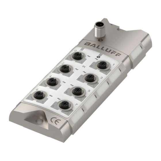
Erste Schritte 3.1. Anschluss- übersicht Abb. 3-1: BNI IOL-719-002-Z012 1 Befestigungsloch 9 Pin/Port LED: Signalstatus 2 Beschriftung 10 Analoger Port 6 3 Status-LED: Kommunikation 11 Analoger Port 4 4 Analoger Port 1 12 Analoger Port 2 5 Analoger Port 3... -
Page 9: Mechanischer Anschluss
Balluff-Netzwerkschnittstelle / IO-Link BNI IOL-719-002-Z012 Erste Schritte 3.2. Mechanischer Die Module der BNI IOL-719-002-Z012 werden mit 2 M6-Schrauben und Anschluss 2 Distanzringen befestigt. 3.3. Elektrischer Für die Module der BNI IOL-719-002-Z012 ist kein separater Anschluss Versorgungsspannungsanschluss erforderlich. Der Strom wird über die IO-Link-Schnittstelle vom übergeordneten IO-Link-Master bereitgestellt. -
Page 10: Funktionalität
Erste Schritte 3.4. Funktionalität Das Modul der BNI IOL-719-002-Z012 hat acht frei konfigurierbare analoge Ports. Die Ports können unabhängig voneinander für den Eingang eines Spannungssignals, Stromsignals, Pt-Sensors oder Thermoelements konfiguriert werden. Eingangstyp Nennbereich Spannung 0 V - 10 V Spannung... - Page 11 Kurzschlussfall abgeschaltet um den Spannungsverlust zu reduzieren. Die Kurzschluss Fehlermeldung wird speichernd gesetzt und kann in den Ausgangsprozessdaten zurückgesetzt werden. Hinweis Bei Stromeingang arbeitet der BNI IOL-719-002-Z012 nur mit 3-Leiter Sensoren. 2-Leiter-Sensoren werden bei Spannungs-oder Stromeingang nicht unterstützt. www.balluff.com...
-
Page 12: Sensorschnittstelle
Erste Schritte PT100 BNI IOL-719-002-Z012 Sensorschnittstelle 2-adrig 3-adrig 4-adrig Achtung! Die Verdrahtung ist mit Vorsicht durchzuführen. Die Eingänge sind vor falscher Verdrahtung geschützt. Aber in einigen Sonderfällen kann es zu Beschädigungen kommen. Vor dem Einschalten des Netzgeräts ist sicherzustellen, dass die Verdrahtung ordnungsgemäß... -
Page 13: Eingangssignalbereich
Nennausgangsbereich. Beispielsweise kann ein Sensor mit einem Ausgang von 0 – 10 V Spannungswerte zwischen -0,5 V und 10,5 V erzeugen. Fehler gibt er mit einem Signal <-0,5 V oder >10,5 V aus. Somit hat die BNI IOL-719-002-Z012 die folgenden Eingangsbereiche für die verschiedenen Analogmodi. - Page 14 0, also eine positive Zahl. In diesem Fall kann die Spannung mit der folgenden Formel berechnet werden: 10,5�� Eingangsspannung [ V ] = Portwert ∗ = 4660 ∗ = 5,974�� ( N−1 ) ( 14−1 ) − 1 − 1 www.balluff.com...
- Page 15 Zahl zwischen 0000 und dem Skalenendwert entsprechend der Auflösung (FFFF 16-Bit-Auflösung) dargestellt. Das Eingangssignal der BNI IOL-719-002-Z012 kann mit den folgenden Formeln aus dem Digitalwert berechnet werden: Spannungseingang (0V-10V; 5V – 10V; -10V - +10V; 0V - 5V; -5V - +5V): −...
- Page 16 Die Auflösung beträgt 16 Bit. Der digitalisierte über IO-Link gelesene Wert beträgt 4567hex = 17767. −T 1200°��− ( −100°�� ) Temperatur [ °C ] = Portwert ∗ + ( −100°C ) = 252,44 °�� = 17767 ∗ −1 −1 www.balluff.com...
-
Page 17: Dimensioniertes Datenformat
Balluff-Netzwerkschnittstelle / IO-Link BNI IOL-719-002-Z012 Erste Schritte 3.10. Dimensioniertes Bei einem dimensionierten Datenformat werden die Spannungs-, Strom- und Datenformat Temperaturmesswerte in mV, µA oder °C (in 0,1°C-Schritten) konvertiert und dieser Wert wird dann als Prozessdaten gesendet. In diesem Fall beeinflussen die Einstellungen für die Auflösung und die Prozessdatenanordnung die Daten nicht. - Page 18 = 15,007 ���� 1000 1000 Beispiel 4: Als Analogmodus ist TypJ-Thermoelement eingestellt. Der digitalisierte über IO-Link gelesene Wert beträgt 06F1hex = 1777. Bei Thermoelement-Eingang hat der dimensionierte Wert die Dimension 0,1°C. Portwert 1777 Temperatur [ °C ] = = 177,7 °�� www.balluff.com...
-
Page 19: Io-Link-Schnittstelle
22 Byte Eingang, 1 Byte Ausgang IO-Link-Revision Frametyp Prozessdatenzykluszeit* 55 ms 1320 ms bei minimaler Zykluszeit Hinweis Es empfiehlt sich, die BNI IOL-719-002-Z012 mit einem IO-Link-Master der Version 1.1 zu verwenden. Bei einem IO-Link-Master der Version 1.0 ist die Prozessdatenzykluszeit extrem hoch. www.balluff.com... -
Page 20: Prozessdaten/Eingangsdaten
Byte Die Schwellenwertbits zeigen ein Überschreiten des Schwellenwerts an. Der Schwellenwert wird über Parameter konfiguriert. (siehe „Schwellenwert aktiviert“, „Schwellenwert 1“ und „Schwellenwert 2“.) Byte Analogwert Port 0 Byte Analogwert Port 1 Byte Analogwert Port 2 Byte Analogwert Port 3 www.balluff.com... - Page 21 Balluff-Netzwerkschnittstelle / IO-Link BNI IOL-719-002-Z012 IO-Link-Schnittstelle Byte Analogwert Port 4 Byte Analogwert Port 5 Byte Analogwert Port 6 Byte Analogwert Port 7 www.balluff.com...
- Page 22 Thermoelementen TypJ-,TypK-, oder Typ C-Sensoren des entsprechenden Ports hin. Unterlauf-Bit: Dieses Bit gibt an, wenn das gemessene Signal unterhalb des ausgewählten Bereichs liegt. Byte Überlauf-Bit: Dieses Bit gibt an, wenn das gemessene Signal oberhalb des ausgewählten Bereichs liegt. www.balluff.com...
- Page 23 Balluff-Netzwerkschnittstelle / IO-Link BNI IOL-719-002-Z012 IO-Link-Schnittstelle Prozess- daten/ Ausgangs- daten Byte Ist ein Eingangsport als Strom- oder Spannungseingang konfiguriert, so wird +24V zwischen Pin 1 und Pin 3 des Eingangsports geschaltet. Diese Spannungsversorgung ist gegen Kurzschluss geschützt. Die Spannungsversorgung wird abgeschaltet um die Spannungsverluste zu reduzieren.
-
Page 24: Bni Iol-719-002-Z012
Herstellercode 2 Byte 0378 050204 Gerätecode 3 Byte Herstellername 7 Byte BALLUFF nur Lesen Herstellertext 15 Byte www.balluff.com BNI IOL-719-002-Z012 Produktname 20 Byte BNI00AJ Produkt-ID 7 Byte Sensor-Hub Analog, 8 Produkttext 32 Byte Analogeingänge Serien-Nr. 16 Byte Hardware-Revision 1 Byte... -
Page 25: Seriennummer Setzen 54Hex
Balluff-Netzwerkschnittstelle / IO-Link BNI IOL-719-002-Z012 IO-Link-Schnittstelle Seriennummer Die Seriennummer hat einen Standardwert von 16x 00 Um den Master-Validierungsmodus „Identity“ verwenden zu können, kann mit diesem setzen 54 Parameter eine Seriennummer festgelegt werden. Dadurch wird verhindert, dass ein Gerät an einen falschen Master-Port angeschlossen wird. - Page 26 IO-Link-Schnittstelle Analogwerte in Prozessdaten bei linker Anordnung für unterschiedliche Auflösungen Byte 10-Bit-Analogwert 12-Bit-Analogwert 14-Bit-Analogwert 16-Bit-Analogwert Analogwerte in Prozessdaten bei rechter Anordnung für unterschiedliche Auflösungen Byte 10-Bit-Analogwert 12-Bit-Analogwert 14-Bit-Analogwert 16-Bit-Analogwert Hinweis Die Prozessdatenanordnung hat beim dimensionierten Datenformat keine Auswirkung. www.balluff.com...
- Page 27 Balluff-Netzwerkschnittstelle / IO-Link BNI IOL-719-002-Z012 IO-Link-Schnittstelle Analogmodus Der Modus der Eingangsports kann mit diesem ISDU-Register festgelegt werden. Bei Zugriff auf das ISDU-Register über Subindex 0 können die Einstellungen für alle Ports können gelesen/geschrieben werden. Bei Zugriff auf das ISDU-Register über Subindex 1-8 kann der Portmodus für den entsprechenden Port...
- Page 28 Bei Zugriff auf das ISDU-Register über Subindex 0 kann die Auflösung für alle Ports gelesen/geschrieben werden. Bei Zugriff auf das ISDU-Register über Subindex 1 -8 kann die Auflösung für den entsprechenden Port (P0-P7) gelesen/geschrieben werden. 0 = Pin 2 1 = Pin 4 Subindex 0: Byte www.balluff.com...
- Page 29 Subindex 0: Byte Kabelbruch Bei Pt100, Pt1000, Typ J, Typ K und Typ C kann die BNI IOL-719-002-Z012 einen Kabelbruch inaktiviert erkennen. In einigen Fällen ist die Kabelbrucherkennung bei Verwendung einer Kalibratoreinheit aktiviert. Damit der Kalibrator zur Modulkalibrierung verwendet werden kann, kann die Kabelbrucherkennung deaktiviert werden.
-
Page 30: Schwellenwert 1, F6Hex Schwellenwert 2, F7Hex
F8 deaktiviert ist, wird das entsprechende Bit in den Prozessdaten auf 0 gesetzt. Wenn ein Schwellenwert aktiviert ist, wird der Analogwert mit dem Schwellenwert verglichen und das entsprechende Bit wird in den Prozessdaten entsprechend dem Ergebnis des Vergleichs gesetzt. www.balluff.com... - Page 31 Balluff-Netzwerkschnittstelle / IO-Link BNI IOL-719-002-Z012 IO-Link-Schnittstelle Erdung Es gibt drei Arten von Thermoelementen: ungeerdet, geerdet und exponiert. Der BNI IOL-719- Thermo- 002-Z012 ist in der Lage, alle zu messen, aber im Falle eines geerdeten Thermoelements wird element F9 der Messbereich reduziert. Das entsprechende Thermoelement muss in der ISDU eingestellt werden, um richtig messen zu können.
-
Page 32: Fehler
Messwert außerhalb des gültigen Bereichs 0x8DF3 Kabelbruch an irgendeinem Port erkannt IO-Link-Revision 1.1 Ereigniscode Beschreibung 0x5111 Niedrige Versorgungsspannung (US1) 0x7710 Kurzschluss an Pin 1 (an mindestens einem Port) 0x8C20 Messwert außerhalb des gültigen Bereichs 0x7700 Kabelbruch an irgendeinem Port erkannt www.balluff.com... -
Page 33: Technische Daten
Balluff-Netzwerkschnittstelle / IO-Link BNI IOL-719-002-Z012 Technische Daten 5.1. Abmessungen 5.2. Mechanische Gehäusematerial Zinkdruckguss Daten IO-Link-Port M12, A-codiert, Stecker Analoge Ports M12, Buchse, 5-polig Gehäuseschutzart gemäß IP67 (nur wenn eingesteckt und eingedreht) IEC 60529 Gewicht ca. 500 g Abmessungen (L × B × H in 68 x 181,5 x 31,8 5.3. - Page 34 Port-Pin LEDs LED “1” – Port Pin 2 LED E-Ports Anzeige Funktionsport-LED Standard Port ist deaktiviert Gelb (LED0) Port ist aktiviert, Eingangssignal im Bereich Rot (LED0) Eingangssignal außerhalb des Bereichs Rot (LED0, LED1) Pin1: Kurzschluss oder Kabelbruch an Port www.balluff.com...
- Page 35 Balluff-Netzwerkschnittstelle / IO-Link BNI IOL-719-002-Z012 Anhang 6.1. Produkt- BNI IOL-719-002-Z012 Bestellcode Balluff-Netzwerkschnittstelle IO-Link-Schnittstelle Funktionen 719 = 8 Analogeingänge Versionen 002 = Basisversion, IO-Link V1.1 Mechanische Ausführung Z012 = Zinkdruckgussgehäuse, matt vernickelt Busanschluss und Netzgerät 1xM12 Außengewinde IO-Ports: 8xM12, Buchse, 5-polig 6.2.
- Page 36 Balluff GmbH Schurwaldstrasse 9 73765 Neuhausen a.d.F. Deutschland Tel.: 07158 173-0 Fax: 07158 5010 www.balluff.com balluff@balluff.de...
- Page 37 BNI IOL-719-002-Z012 User´s Guide...
- Page 38 3.10. Dimensioned data format IO-Link Interface 4.1. IO-Link Data 4.2. Prozess data / Input data BNI IOL-719-002-Z012 4.3. Process data / Output data BNI IOL-719-002-Z012 4.4. Parameter data / Request data Setting the serial number 54hex Process data alignment 59hex...
- Page 39 Balluff Network Interface / IO-Link BNI IOL-719-002-Z012 5.2. Mechanical Data 5.3. Electrical Data 5.4. Operating conditions 5.5. LED indicators Status LEDs Port-Pin LEDs LED I-Ports Standard Appendix 6.1. Product ordering code 6.2. Order information Included material www.balluff.com...
-
Page 40: Notes For The User
Cross references indicate where additional information on the topic can be found. 1.3. Symbols Attention! This symbol indicates a security notice which must be observed. Note This symbol indicates general notes. 1.4. Abbreviations Balluff Network Interface Direct Parameter Page Electromagnetic Compatibility Function Earth IO-Link ISDU Index Service Data Unit Most significant bit 1.5. -
Page 41: Safety
Safety 2.1. Intended use This guide describes the Balluff Network Interface BNI IOL-719-002-Z012 for the application as peripheral analog input module to establish connection of analog sensors, RTDs and thermocouple sensors. Hereby it is about an IO-Link device which communicates by means of IO-Link protocol with the superordinate IO-Link master assembly. -
Page 42: Getting Started
Getting Started 3.1. Connection overview Fig. 3-1: BNI IOL-719-002-Z012 1 Mounting hole 9 Pin/Port LED: Signalstatus 2 Label 10 Analog port 6 3 Status LED: Communication 11 Analog port 4 4 Analog port 1 12 Analog port 2 5 Analog port 3... -
Page 43: Mechanical Connection
Balluff Network Interface / IO-Link BNI IOL-719-002-Z012 Getting Started 3.2. Mechanical The BNI IOL-719-002-Z012 modules are attached by using 2 M6 screws and connection 2 spacers. 3.3. Electrical The BNI IOL-719-002-Z012 modules require no separate supply voltage connection. Power connection is provided through the IO-Link interface by the host IO-Link Master. - Page 44 Getting Started 3.4. Functionality The BNI IOL-719-002-Z012 module has eight free configurable analog port. The ports can be configured independently to accept voltage signal, current signal, Pt sensor or thermocouples. Input type Nominal range Voltage 0 V - 10 V...
- Page 45 The short circuit error is latched and it can be reset with the output process data. Note In case of current input, the BNI IOL-719-002-Z012 works only with 3-wire sensors. 2-wire-sensors are not supported with voltage or current input.
-
Page 46: Sensor Interface
Getting Started PT100 BNI IOL-719-002-Z012 Sensor Interface 2-wire 3-wire 4-wire Attention! A care must be taken during wiring. The inputs are protected against wrong wiring, but in some special cases damage can be occurred. Be sure to connect the wiring properly before turning power supply on. -
Page 47: Input Signal Range
(grounded) 3.7. Data formats The signal on the input port of the BNI IOL-719-002-Z012 will be digitalized and sent as a process data over IO-Link. There are 16 bits reserved in the process data for each port. The digitalized value can be represented in different formats (signed, unsigned or dimensioned), in different resolution (16, 14, 12 or 10 bit), with different alignment (left or right aligned). - Page 48 0, so it is a positive number. In this case the voltage can be calculated with the following formula: 10.5�� Input voltage [ V ] = PortValue ∗ = 4660 ∗ = 5,974�� ( N−1 ) ( 14−1 ) − 1 − 1 www.balluff.com...
- Page 49 (FFFF in case of 16 bit resolution). The input signal on the BNI IOL-719-002-Z012 can be calculated from the digital value with the following formulas: Voltage input (0V-10V, 5V – 10V, -10V - +10V, 0V - 5V, -5V - +5V): −...
- Page 50 The resolution is 16 bit The digitalized value read over IO-Link is 4567hex = 17767 −T 1200°��− ( −100°�� ) Temperature [ °C ] = PortValue ∗ + ( −100°C ) = 252.44 °�� = 17767 ∗ −1 −1 www.balluff.com...
- Page 51 Balluff Network Interface / IO-Link BNI IOL-719-002-Z012 Getting Started 3.10. Dimensioned In case of dimensioned format, the measured voltage, current or temperature will be data format converted to mV, uA or °C (in 0.1 °C step), and this value will be sent as a process data. In this case the resolution and process data alignment settings do not influence the data.
- Page 52 The analog mode is set to TypJ Thermocouple. The digitalized value read over IO-Link is 06F1hex = 1777 In case of Thermocouple input, the dimensioned value has the dimension of 0.1 °C PortValue 1777 Temperature [ °C ] = = 177.7 °�� www.balluff.com...
-
Page 53: Io-Link Interface
Process data cycle time* 55 ms 1320 ms * by min. cycle time Note It is recommended to use the BNI IOL-719-002-Z012 with an IO-Link 1.1 master. In case of IO-Link 1.0 master, the process data cycle time will be extreme high. www.balluff.com... -
Page 54: Prozess Data / Input Data
The switch point bits show a switch point overrun. The switch point can be configured by parameter. (see "Switch Point Enable", "Switch Point 1" and "Switch Point 2") Byte Analog value Port 0 Byte Analog value Port 1 Byte Analog value Port 2 Byte Analog value Port 3 www.balluff.com... - Page 55 Balluff Network Interface / IO-Link BNI IOL-719-002-Z012 IO-Link Interface Byte Analog value Port 4 Byte Analog value Port 5 Byte Analog value Port 6 Byte Analog value Port 7 www.balluff.com...
- Page 56 Pt100, Pt1000 and thermocouple sensors on the corresponding port. Underflow bit: This bit indicates when the measured signal is lower than the selected range. Byte Overflow bit: This bit indicates when the measured signal is higher than the selected range. www.balluff.com...
-
Page 57: Process Data / Output Data
Balluff Network Interface / IO-Link BNI IOL-719-002-Z012 IO-Link Interface 4.3. Process data / Output data BNI IOL- Byte 719-002- Z012 When an input port is configured as a voltage or current input, +24V voltage will be switched between pin1 and pin3 of the input port. This supply voltage is short circuit protected. The supply voltage will be switched off in case of short circuit, in order to reduce the power dissipation. -
Page 58: Parameter Data / Request Data
2 bytes 0378 050204 Device ID 3 bytes Vendor name 7 bytes BALLUFF Vendor text 15 bytes www.balluff.com BNI IOL-719-002-Z012 read only Product name 20 bytes BNI00AJ Product ID 7 bytes Sensorhub Analog, 8 Product text 32 bytes Analog Input... -
Page 59: Setting The Serial Number 54Hex
Balluff Network Interface / IO-Link BNI IOL-719-002-Z012 IO-Link Interface Setting the The serial number has a default value of 16x 00 serial number In order to use the "Identity" master validation mode, a serial number can be set using this parameter. - Page 60 Analog values in process data in case of right justification for different resolutions. Byte 10 bit analog value 12 bit analog value 14 bit analog value 16 bit analog value Note The process data alignment do not have effect in case of dimensioned data format www.balluff.com...
- Page 61 Balluff Network Interface / IO-Link BNI IOL-719-002-Z012 IO-Link Interface Analog The mode of the input ports can be set with this ISDU register. mode F0 Accessing the ISDU register through the subindex 0, the settings for all ports can be read/written.
- Page 62 Accessing the ISDU register through the subindex 0, the resolution for all ports can be read/written. Accessing the ISDU register through subindex 1-8, the resolution for the corresponding port (P0-P7) can be read/written, 0 = Pin 2 1 = Pin 4 Subindex 0: Byte www.balluff.com...
- Page 63 Subindex 0: Byte Wire break In case of Pt 100, Pt1000, Typ J, Typ K and Type C the BNI IOL-719-002-Z012-XXX can detect disable F4 wire break condition. In some cases with a calibrator unit, the wire break detection will be activated.
-
Page 64: Switch Point 1, F6Hex Switch Point 2, F7Hex
0. When a switch point is enabled, the analog value will be compared to the switch point value, and the corresponding bit will be set in the process data according to the result of the comparison. www.balluff.com... - Page 65 Balluff Network Interface / IO-Link BNI IOL-719-002-Z012 IO-Link Interface Thermo- There are three types of thermocouples: ungrounded, grounded and exposed. The BNI IOL-719- couple 002-Z012 is able to measure all of them, but in case of grounded thermocouple the grounding measurement range is reduced.
-
Page 66: Error
Wire break detected on some port IO-Link Revision 1.1 Event Code Description 0x5111 Low supply voltage (US1) 0x7710 Short circuit on pin1 (on at least one of the ports) 0x8C20 Measurement value is out of range 0x7700 Wire break detected on some port www.balluff.com... -
Page 67: Technical Data
Balluff Network Interface / IO-Link BNI IOL-719-002-Z012 Technical Data 5.1. Dimensions 5.2. Mechanical Housing material Die-cast zinc housing Data IO-Link-Port M12, A-coded, male, Analog Ports M12, female, 5-poles Enclosure rating per IEC 60529 IP67 (only when plugged in and threaded in) Weight ca. - Page 68 Indicator Function Port LED Standard Port is switched off Yellow static (LED0) Port is switched on, input signal is in range Red (LED0) Input signal is out of range Red (LED0, LED1) Pin1 short circuit or wirebreak on port www.balluff.com...
- Page 69 Balluff Network Interface / IO-Link BNI IOL-719-002-Z012 Appendix 6.1. Product BNI IOL-719-002-Z012 ordering code Balluff Network Interface IO-Link Interface Functions 719 = 8 analog inputs Versions 002 = Base version, IO-Link V1.1 Mechanical design Z012 = Die-cast zinc housing, matte nickel plated...
- Page 70 Balluff GmbH Schurwaldstrasse 9 73765 Neuhausen a.d.F. Germany Tel. +49 7158 173-0 Fax +49 7158 5010 www.balluff.com balluff@balluff.de...
- Page 71 BNI IOL-719-002-Z012 用户指南...
- Page 72 巴鲁夫网络接口/IO-Link BNI IOL-719-002-Z012 目录 用户须知 1.1. 本指南的结构 1.2. 印刷规则 列举 行动 语法 交叉引用 1.3. 符号 1.4. 缩写 1.5. 视图偏差 1.6. 处置 安全 2.1. 既定用途 2.2. 安装和启动 2.3. 一般安全性注意事项 2.4. 对腐蚀性物质的耐受性 危险电压 入门介绍 3.1. 接口概览 3.2. 机械连接 3.3. 电气连接 IO-Link 接口...
- Page 73 开关点 1,F6 开关点 2,F7 开关点启用 F8 热电偶接地 F9 电压传感器断线检测 FB 4.5. 错误 4.6. 事件 技术数据 5.1. 尺寸 5.2. 机械数据 5.3. 电气数据 5.4. 工作条件 5.5. LED 指示灯 状态 LED 端口-针脚 LED 标准端口 LED 附录 6.1. 产品订购代码 6.2. 订购信息 供货清单 注释 www.balluff.com...
- Page 74 巴鲁夫网络接口/IO-Link BNI IOL-719-002-Z012 用户须知 1.1. 本指南的结构 本指南的组织结构方便各章节互相引用: 第 2 节:基本安全说明。 第 3 节:设备安装的主要步骤。 …….. 1.2. 印刷规则 本指南中使用了以下编排规则。 列举 列举以带项目符号的列表形式显示。 列举 1, • 列举 2。 • 行动 操作说明以三角形打头。操作结果以箭头指示。 操作指示 1。 ➢ 操作结果。 操作指示 2。 ➢ 语法 数字: 十进制的数字不带任何上下标(如:123), 十六进制的数字带 hex 下标(如:00hex)。...
- Page 75 巴鲁夫网络接口/IO-Link BNI IOL-719-002-Z012 安全 2.1. 既定用途 本指南介绍了巴鲁夫 BNI IOL-719-002-Z012 网络接口,此接口用于作为外围模拟量输入模块 来连接模拟量传感器、RTD 和热电偶传感器。因此,它是通过 IO-Link 协议与上级 IO-Link 主 站组件进行通信的 IO-Link 设备。 2.2. 安装和启动 注意! 安装和启动只能由受过培训的专业人员执行。合格人员是指熟悉产品的安装和操作, 并具备此项活动所需资格的人员。 非法篡改或不当使用造成的任何损坏均会导致制造 商保证和保修失效。操作人员负责确保遵守适用的安全和事故预防规定。 2.3. 一般安全性 调试与检查 注意事项 进行调试之前,应仔细阅读本操作手册。 不得在人员安全取决于设备功能的场合中使用本系统。 经授权的人员 只能由经培训的专业人员执行安装和调试。 既定用途 质保以及向制造商提起的责任索赔在以下情况下将失效: • 未授权篡改 使用不当 •...
- Page 76 巴鲁夫网络接口/IO-Link BNI IOL-719-002-Z012 入门介绍 3.1. 接口概览 图 3-1:BNI IOL-719-002-Z012 1 安装孔 9 针脚/端口 LED:信号状态 2 标记 10 模拟量端口 6 3 状态 LED:通信 11 模拟量端口 4 4 模拟量端口 1 12 模拟量端口 2 5 模拟量端口 3 13 模拟量端口 0 6 模拟量端口 5 14 状态...
- Page 77 巴鲁夫网络接口/IO-Link BNI IOL-719-002-Z012 入门介绍 3.2. 机械连接 BNI IOL-719-002-Z012 模块通过两个 2 M6 螺钉和 2 个垫圈固定。 3.3. 电气连接 BNI IOL-719-002-Z012 模块不需要连接单独的电源。由 IO-Link 主站通过 IO-Link 接口供电。 IO-Link 接口 IO-Link(M12,A 编码,公头) 针脚 功能 电源控制器,+24 V,最大 1.1 A 接地,参考电位 C/Q,IO-Link 数据传输信道 连接传感器 Hub 将保护接地连接到 FE 端子(如有)。...
- Page 78 巴鲁夫网络接口/IO-Link BNI IOL-719-002-Z012 入门介绍 3.4. 功能 BNI IOL-719-002-Z012 模块具有 8 个可任意配置的模拟量端口。这些端口可以独立配置,以 接收电压信号、电流信号、Pt 传感器信号或热电偶信号。 输入类型 标称范围 电压 0 V - 10 V 电压 5 V - 10 V 电压 -10 V - +10 V 0 V – 5 V 电压 电压...
- Page 79 电流源 - 模拟量输入 - 模拟量输入 + 电流源 + 针脚 J 型、K 型、C 型* 热电偶 热电偶 + 热电偶 - 从固件 3.0 版开始可用 注 +24V 电源有短路保护。 发生短路时, 将切断电源, 以降低能耗。 短路错误将被锁存, 可以通过输出过程数据来重置。 注 如果是电流输入,则 BNI IOL-719-002-Z012 仅搭配 3 线制传感器。 不支持 2 线制传感器的电压或电流输入。 www.balluff.com...
- Page 80 巴鲁夫网络接口/IO-Link BNI IOL-719-002-Z012 入门介绍 PT100 BNI IOL-719-002-Z012 传感器接口 2 线 3 线 4 线 注意! 接线时,必须非常小心。输入端具有防误接保护,但在某些特殊情况下,也可能发生 损坏。在接通电源之前,务必确保正确接线。 注 未使用的 I/O 端口必须安装保护盖,以确保达到 IP67 防护等级。 注 应使用屏蔽电缆将模拟量信号传输到 BNI IOL-719-002-Z012 注 为了提高热电偶测量的精度,应使用热电偶专用 M12 插头(J 型、K 型、C 型,取决 于具体的热电偶)将热电偶连接到设备。 www.balluff.com...
- Page 81 C 型 (接地型) 3.7. 数据格式 BNI IOL-719-002-Z012 输 入 端 口 上 的 信 号 将 进 行 数 字 化 处 理 , 并 作 为 过 程 数 据 通 过 IO-Link 发送。过程数据中为每个端口预留 16 位。数字化值可以用不同的格式(有符号、无符 号或量纲化)、不同的分辨率(16、14、12 或 10 位)以及不同的对齐方式(左对齐或...
- Page 82 巴鲁夫网络接口/IO-Link BNI IOL-719-002-Z012 入门介绍 3.8. 有符号数据格式 如果是有符号数据格式,则数字化值以二进制补码格式(15 位 + 符号、13 位 + 符号、11 位 + 符号、9 位 + 符号,取决于具体的分辨率)来表示。 对于不同的配置,可以通过以下公式计算模拟量信号(电压、电流、温度)。 电压输入 (0V-10V, -10V - +10V, 0V - 5V, -5V - +5V): 如果是正数 (MSB = 0): Input voltage [ V ] = PortValue ∗...
- Page 83 − 1 3.9. 无符号数据格式 如果是无符号数据格式,所选择的输入范围将根据相应的分辨率,以介于 0000 至满量程值 范围内的数字表示(FFFF (如果分辨率为 16 位))。可以根据此数字值,通过以下公式计 算 BNI IOL-719-002-Z012 上的输入信号: 电压输入 (0V-10V、5V – 10V、-10V - +10V、0V - 5V、-5V - +5V): − V Input voltage [ V ] = PortValue ∗ + �� ������ − 1 电流输入...
- Page 84 巴鲁夫网络接口/IO-Link BNI IOL-719-002-Z012 入门介绍 示例 2: 模拟量模式设置为 4-20 mA 分辨率为 12 位。 过程数据为左对齐。 通过 IO-Link 读取的数字化值为 ABC0 。 如果是 4-20 mA,则模拟量输入电流范围为 3.8 mA 至 20.5 mA。数字化值作为 16 位值通过 IO-Link 来读取,但其分辨率为 12 位,且为左对齐,因此,这个 12 位数字化值便是 ABC 2748。 − I 20.5���� − 3.8����...
- Page 85 巴鲁夫网络接口/IO-Link BNI IOL-719-002-Z012 入门介绍 3.10. 量纲化数据格式 如果是量纲化格式, 则测得的电压、 电流或温度将被转换为 mV、 uA 或 °C 值 (步长为 0.1 °C) , 且这个值将作为过程数据发送。在这种情况下,分辨率和过程数据对齐设置不影响数据。它始 终被视为右对齐数据,并为 16 位值的形式。 电压输入 (0V-10V, 5V – 10V, -10V - +10V, 0V - 5V, -5V - +5V): 如果是正数 (MSB = 0):...
- Page 86 巴鲁夫网络接口/IO-Link BNI IOL-719-002-Z012 入门介绍 示例 2: 模拟量模式设置为 0-10V。 通过 IO-Link 读取的数字化值为 EC78 = 60536。 如果是电压输入,则量纲化值的量纲为 mV。 PortValue − 65536 60536 − 65536 Input voltage [ V ] = = −5.000�� 1000 1000 示例 3: 模拟量模式设置为 4-20 mA 通过 IO-Link 读取的数字化值为 3A9F = 15007。...
- Page 87 IO-Link 接口 4.1. IO-Link 数据 BNI IOL-719-002-Z012-XXX 数据传输速率 COM2 (38,4 kBaud) 最短循环时间 55 ms 过程数据长度 22 个字节的输入,1 个字节的输出 IO-Link 版本 帧类型 过程数据循环时间* 55 ms 1320 ms * 即,最短循环时间 注 建议将 BNI IOL-719-002-Z012 与 IO-Link 1.1 主站一起使用。如果是 IO-Link 1.0 主 站,则过程数据循环时间将非常长。 www.balluff.com...
- Page 88 巴鲁夫网络接口/IO-Link BNI IOL-719-002-Z012 IO-Link 接口 4.2. 过程数据/ 输入数据 BNI IOL-719- 002-Z012 字节 位 开关点位指示开关点溢出。开关点可以通过参数进行配置。(请参见“开关点启用”、“开关点 1” 和“开关点 2”) 字节 位 模拟值端口 0 字节 位 模拟值端口 1 字节 位 模拟值端口 2 字节 位 模拟值端口 3 www.balluff.com...
- Page 89 巴鲁夫网络接口/IO-Link BNI IOL-719-002-Z012 IO-Link 接口 字节 位 模拟值端口 4 字节 位 模拟值端口 5 字节 位 模拟值端口 6 字节 位 模拟值端口 7 www.balluff.com...
- Page 90 巴鲁夫网络接口/IO-Link BNI IOL-719-002-Z012 IO-Link 接口 字节 位 “针脚 1 短路,接线断开”位:在相应端口被配置为电压或电流输入的情况下,此位指示传感器电源 的短路状态,或者在相应端口被配置为电压输入、Pt100、Pt1000 和热电偶传感器的情况下,此位指 示断线状态。 “下溢”位:此位指示测得的信号何时低于所选范围。 字节 位 “上溢”位:此位指示测得的信号何时高于所选范围。 www.balluff.com...
- Page 91 巴鲁夫网络接口/IO-Link BNI IOL-719-002-Z012 4.3. 过程数据/ 输出数据 BNI IOL- 字 719-002- 位 节 Z012 当输入端口被配置为电压或电流输入时,将在输入端口的针脚 1 与针脚 3 之间切换 +24V 电源。此 电源有短路保护。发生短路时,将切断电源,以降低能耗。短路错误将被锁存,可以将输出过程数据 中的相应位进行 0 -> 1 转换来重置这个错误。 注 如果使用启动电流增大的传感器。 短路监测可以在传感器启动时被触发。 如果你能观察到这种现象,请联系相关的服务支持部门。 请联系负责的支持部门。 他们可以协助你延迟短路信息的出现。 www.balluff.com...
- Page 92 巴鲁夫网络接口/IO-Link BNI IOL-719-002-Z012 IO-Link 接口 4.4. 参数数据/ ISDU 子索 对象名称 长度 测量范围 默认值 请求数据 索引 索引 引 供应商 ID 2 字节 0378 050204 子站设备 ID 3 字节 供应商名称 7 字节 巴鲁夫 供应商文本 15 字节 www.balluff.com 20 个 BNI IOL-719-002-Z012 产品名称...
- Page 93 巴鲁夫网络接口/IO-Link BNI IOL-719-002-Z012 IO-Link 接口 设置序列号 序列号的默认值为 16x 00 。 为了使用“身份”主站验证模式,可以使用此参数设置序列号。 这可以防止设备连接到错误的主站端口 注 建议为每个设备设置唯一序列号,并选用“身份”主站验证模式。 过程数据对齐 模拟值在过程数据中作为 16 位值通过 IO-Link 发送。 如果分辨率为 10、12 或 14 位,模拟值将填充 0,以便在过程数据中补足 16 位。10、12 或 14 位值的对齐方式可以在过程数据对齐 ISDU 寄存器中设置。 0 = 左对齐 1 = 右对齐 www.balluff.com...
- Page 94 巴鲁夫网络接口/IO-Link BNI IOL-719-002-Z012 IO-Link 接口 不同分辨率下左对齐过程数据中的模拟值。 字节 位 10 位模拟值 12 位模拟值 14 位模拟值 16 位模拟值 不同分辨率下右对齐过程数据中的模拟值。 字节 位 10 位模拟值 12 位模拟值 14 位模拟值 16 位模拟值 注意 如果是量纲化数据格式,过程数据对齐将不起作用 www.balluff.com...
- Page 95 巴鲁夫网络接口/IO-Link BNI IOL-719-002-Z012 IO-Link 接口 模拟量模式 输入端口的模式可以通过这个 ISDU 寄存器设置。 在通过子索引 0 访问 ISDU 寄存器时,可以读取/写入所有端口的设置。在通过子索引 1-8 访问 ISDU 寄存器时,可以读取/写入相应端口 (P0-P7) 的端口模式。 = 电压输入,0V – 10V = 电流输入,4mA – 20 mA = 电压输入,5V – 10V = 电压输入,-10V – 10V = 电压输入,0V – 5V = 电流输入,0mA –...
- Page 96 巴鲁夫网络接口/IO-Link BNI IOL-719-002-Z012 IO-Link 接口 分辨率 F1 模拟值的分辨率可以通过这个 ISDU 寄存器设置。 在通过子索引 0 访问 ISDU 寄存器时,可以读取/写入所有端口的分辨率。在通过子索引 1-8 访问 ISDU 寄存器时,可以读取/写入相应端口 (P0-P7) 的分辨率。 0 = 16 位分辨率 1 = 14 位分辨率 2 = 12 位分辨率 3 = 10 位分辨率 子索引 0: 字节...
- Page 97 在通过子索引 0 访问 ISDU 寄存器时,可以读取/写入所有端口的分辨率。在通过子索引 1-8 访问 ISDU 寄存器时,可以读取/写入相应端口 (P0-P7) 的分辨率。 0 = 2 线制测量 1 = 3 线制测量 2 = 4 线制测量 子索引 0: 字节 禁用断线检测 如果是 Pt100、Pt1000、J 型热电偶、K 型热电偶和 C 型热电偶模式,BNI IOL-719-002-Z012-XXX 可以检测断线状态。在某些搭配了校准单元的情况下,将激活断线检测。为了能够使用校准仪来校 准模块,可以禁用断线检测。 建议在正常工作期间启用断线检测。 0 = 已启用 1 = 已禁用 过程数据格式 过程数据中的模拟值可以用不同格式表示。...
- Page 98 巴鲁夫网络接口/IO-Link BNI IOL-719-002-Z012 IO-Link 接口 开关点 可以为每个端口设置两个开关点。当模拟值大于开关点值时,将设置过程数据中的相应位。 每个开关点 ISDU 寄存器的长度为 16 字节。在通过子索引 0 访问 ISDU 寄存器时,可以读取/写入 1,F6 开关点 所有端口的开关点值。在通过子索引 1-8 访问 ISDU 寄存器时,可以读取/写入相应端口 (P0-P7) 的 开关点。 2,F7 子索引 0: 字节 字节 为了避免过程数据中的开关点位闪变, 开关点的评估滞后进行。 不同输入类型的滞后在下表中列出。 输入类型 滞后 电压 5 mV 电流...
- Page 99 巴鲁夫网络接口/IO-Link BNI IOL-719-002-Z012 IO-Link 接口 热电偶接地 热电偶有三种类型:非接地型、接地型和无保护型。BNI IOL-719-002-Z012 能够测量所有这些类 型,但如果是接地型热电偶,测量范围会有所减小。如要正确测量热电偶,必须在 ISDU 中设置热 电偶类型。 0 = 非接地型热电偶 1 = 接地型热电偶 子索引 0: 字节 如果是非接地型和无保护型热电偶,应选择非接地测量模式。如果是无保护型热电偶,热接点不得 电连接到导电表面。 如果是接地型热电偶,必须将热电偶的护套接地。 电压传感器断 对于被配置用于电压输入的输入端口,可以开启断线检测,以便检测断线或者配置不当的传感器连 线检测 FB 接。此功能默认处于禁用状态。 0 = 已禁用 1 = 已启用 子索引 0: 字节 位...
- Page 100 巴鲁夫网络接口/IO-Link BNI IOL-719-002-Z012 IO-Link 接口 4.5. 错误 出错代码 说明 索引不可用 0x8011 子索引不可用 0x8012 拒绝访问 0x8023 参数值不在范围内 0x8030 参数长度超限 0x8033 参数长度不足 0x8034 4.6. 事件 IO-Link 版本 1.0 事件代码 说明 供电电压不足 (US1) 0x5112 (至少一个端口的)针脚 1 短路 0x5160 测量值不在范围内 0x8C20 在某个端口上检测到断线 0x8DF3 IO-Link 版本 1.1 事件代码...
- Page 101 巴鲁夫网络接口/IO-Link BNI IOL-719-002-Z012 技术数据 5.1. 尺寸 5.2. 机械数据 外壳材质 压铸锌外壳 IO-Link 端口 M12,A 编码,公头, 模拟量端口 M12,母头,5 针 符合 IEC 60529 标准的外壳防护 IP67(仅在插入并拧紧状态时) 等级 重量 大约 500 g 尺寸(宽 x 高 x 深)(mm) 68 x 181,5 x 31,8 5.3. 电气数据 工作条件...
- Page 102 巴鲁夫网络接口/IO-Link BNI IOL-719-002-Z012 技术数据 5.5. LED 指示灯 状态 LED 指示器 功能 绿灯/红灯 电源模块良好/欠压 LED 1 绿灯/绿灯闪烁 通信错误/通信良好 LED 6 端口-针脚 LED LED “0” – 端口针脚 4 LED “1” – 端口针脚 2 标准端口 LED 指示器 端口 LED 的含义 熄灭 端口关闭 黄灯常亮 (LED0) 端口关闭,输入信号在有效范围内...
- Page 103 巴鲁夫网络接口/IO-Link BNI IOL-719-002-Z012 附录 6.1. 产品订购代码 BNI IOL-719-002-Z012 巴鲁夫网络接口 IO-Link 接口 功能 719 = 8 个模拟量输入 版本 002 = 基础版本,IO-Link V1.1 机械版本 Z012 = 压铸锌外壳,镀镍亚光表面 总线连接和电源 1xM12 外螺纹 IO 端口:8xM12,母头,5 针 6.2. 订购信息 产品订购代码 订购代码 BNI IOL-719-002-Z012 BNI00AJ 供货清单 BNI IOL... 包含以下部件:...
- Page 104 巴鲁夫网络接口/IO-Link BNI IOL-719-002-Z012 注释 www.balluff.com...
- Page 105 巴鲁夫自动化(上海)有限公司 上海市浦东新区成山路 800 号 云顶国际商业广场 A 座 8 层 热线电话:400 820 0016 传真:400 920 2622 www.balluff.com 邮箱:sales.sh@balluff.com.cn...
- Page 106 Americas Service Center Asia Pacific Service Center Poland Greater China Balluff Sp. z o.o. Balluff Inc. Balluff Automation (Shanghai) Co., Ltd. Ul. Graniczna 21A 8125 Holton Drive No. 800 Chengshan Rd, 8F, Building A, 54-516 Wrocław Florence, KY 41042 Yunding International Commercial Plaza...
Need help?
Do you have a question about the BNI IOL-719-002-Z012 and is the answer not in the manual?
Questions and answers