Table of Contents
Advertisement
Quick Links
Advertisement
Table of Contents

Related Manuals for Balluff BNI IOL-719-002-Z012-C10


Summary of Contents for Balluff BNI IOL-719-002-Z012-C10
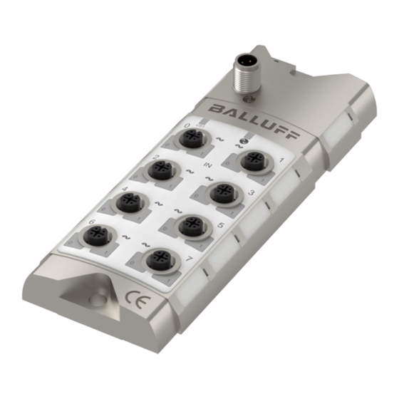
- Page 1 BNI IOL-719-002-Z012 BNI IOL-719-002-Z012-C10 User´s Guide...
-
Page 2: Table Of Contents
Pt100/Pt1000 mode F3hex Wire break disable F4hex Process data format F5hex Switch point 1, F6hex Switch point 2, F7hex Switch point enable F8hex Thermocouple grounding F9 Voltage sensor wire break detection FB 4.5. Error 4.6. Events Technical Data 5.1. Dimensions www.balluff.com... - Page 3 Balluff Network Interface / IO-Link BNI IOL-719-002-Z012-XXX 5.2. Mechanical Data 5.3. Electrical Data 5.4. Operating conditions 5.5. LED indicators Status LEDs Port-Pin LEDs LED I-Ports Standard Appendix 6.1. Product ordering code 6.2. Order information Included material Notes www.balluff.com...
-
Page 4: Notes For The User
Cross references indicate where additional information on the topic can be found. 1.3. Symbols Attention! This symbol indicates a security notice which must be observed. Note This symbol indicates general notes. 1.4. Abbreviations Balluff Network Interface Direct Parameter Page Electromagnetic Compatibility Function Earth IO-Link ISDU Index Service Data Unit Most significant bit 1.5. -
Page 5: Safety
Attention! voltage Disconnect all power before servicing equipment. Note In the interest of product improvement, the Balluff GmbH reserves the right to change the specifications of the product and the contents of this manual at any time without notice. www.balluff.com... -
Page 6: Getting Started
11 Analog port 4 4 Analog port 1 12 Analog port 2 5 Analog port 3 13 Analog port 0 6 Analog port 5 14 Status LED: Module supply 7 Analog port 7 15 IO-Link Interface 8 Mounting hole 16 FE connection www.balluff.com... -
Page 7: Mechanical Connection
Balluff Network Interface / IO-Link BNI IOL-719-002-Z012-XXX Getting Started 3.2. Mechanical The BNI IOL-719-002-Z012-XXX modules are attached by using 2 M6 screws and connection 2 spacers. 3.3. Electrical The BNI IOL-719-002-Z012-XXX modules require no separate supply voltage connection. connection Power is provided through the IO-Link interface by the host IO-Link Master. -
Page 8: Functionality
In case of RTD sensor (Pt100, Pt1000), the sensor can be connected with 2 wire, 3 wire or 4 wire method. You can only connect Thermocouples of the Type J & K & C*. • *Only available at module finishing with C10 www.balluff.com... -
Page 9: Sensor Interface
Balluff Network Interface / IO-Link BNI IOL-719-002-Z012-XXX Getting Started 3.5. Sensor Interface Standard I/O-port (M12, A-coded, female) Voltage / Current input +24 V, 150 mA (sensor supply) Voltage / current input GND (sensor supply, measurement) Voltage / current input Pt100, Pt1000 2 wire... - Page 10 Note In order to achieve better accuracy in case of thermocouple measurement, the thermocouple should be connected to the device with a special M12 connector for thermocouples (Typ J or Typ K, Typ C depending on the thermocouple.) . www.balluff.com...
-
Page 11: Input Signal Range
Balluff Network Interface / IO-Link BNI IOL-719-002-Z012-XXX Getting Started 3.6. Input signal range The BNI IOL-719-002-Z012-XXX supports many standard input signal ranges. In some cases an analog sensor has higher linear output range than the nominal output range. For example a sensor with a 0 – 10 V output can source voltages between -0.5V and 10.5V, and indicates error with a signal <-0.5V or >10.5V. -
Page 12: Signed Data Format
0, so it is a positive number. In this case the voltage 10.5���� Input voltage [ V ] = PortValue ∗ = 4660 ∗ = 5,974���� can be calculated with the following formula: − 1 − 1 ( N−1 ) ( 14−1 ) www.balluff.com... -
Page 13: Unsigned Data Format
Balluff Network Interface / IO-Link BNI IOL-719-002-Z012-XXX Getting Started Example 2: The analog mode is set to -10V - +10V The resolution is 12 bit. The process data is left aligned. The digitalized value read over IO-Link is ABC0 The 12 bit value is left aligned, so the 16 bit value read over IO-Link must be shifted right by four (the 12 bit value is ABC ). - Page 14 The resolution is 16 bit The digitalized value read over IO-Link is 4567hex = 17767 Temperature [ °C ] = PortValue ∗ = 17767 ∗ + ( −100°C ) = 252.44 °���� 1200°����− ( −100°���� ) −T −1 −1 www.balluff.com...
-
Page 15: Dimensioned Data Format
Balluff Network Interface / IO-Link BNI IOL-719-002-Z012-XXX Getting Started 3.10. Dimensioned In case of dimensioned format, the measured voltage, current or temperature will be data format converted to mV, uA or °C (in 0.1 °C step), and this value will be sent as a process data. In this case the resolution and process data alignment settings do not influence the data. - Page 16 The analog mode is set to TypJ Thermocouple. The digitalized value read over IO-Link is 06F1hex = 1777 In case of Thermocouple input, the dimensioned value has the dimension of 0.1 °C PortValue 1777 Temperature [ °C ] = = 177.7 °���� www.balluff.com...
-
Page 17: Io-Link Interface
Balluff Network Interface / IO-Link BNI IOL-719-002-Z012-XXX IO-Link Interface 4.1. IO-Link Data BNI IOL-719-002-Z012-XXX Data transmission rate COM2 (38,4 kBaud) Minimal cycle time 55 ms Process data lenght 22 Byte input, 1 Byte output IO-Link Revision Frame typ Process data cycle time* 55 ms 1320 ms * by min. -
Page 18: Prozess Data / Input Data
The switch point bits show a switch point overrun. The switch point can be configured by parameter. (see "Switch Point Enable", "Switch Point 1" and "Switch Point 2") Byte Analog value Port 0 Byte Analog value Port 1 Byte Analog value Port 2 Byte Analog value Port 3 www.balluff.com... - Page 19 Balluff Network Interface / IO-Link BNI IOL-719-002-Z012-XXX IO-Link Interface Byte Analog value Port 4 Byte Analog value Port 5 Byte Analog value Port 6 Byte Analog value Port 7 www.balluff.com...
-
Page 20: Process Data / Output Data
The short circuit error is latched and it can be reset with a 0 -> 1 transition on the corresponding bit in the output process data. www.balluff.com... -
Page 21: Parameter Data / Request Data
Balluff Network Interface / IO-Link BNI IOL-719-002-Z012-XXX IO-Link Interface 4.4. Parameter data ISDU / Request data Object name Length Range Default value Sub- Index Index Index Vendor ID 2 bytes 0378 050204 Device ID 3 bytes 05020C Vendor name 7 bytes... -
Page 22: Setting The Serial Number 54Hex
In case of 10, 12 or 14 bit resolution the analog value is padded with zeros in order to fill the 16 bit in the process data. The justification of the 10, 12 or 14 bit value can be set in Process data alignment ISDU register. 0 = Left justified 1 = Right justified www.balluff.com... - Page 23 Balluff Network Interface / IO-Link BNI IOL-719-002-Z012-XXX IO-Link Interface Analog values in process data in case of left justification for different resolutions. Byte 10 bit analog value 12 bit analog value 14 bit analog value 16 bit analog value Analog values in process data in case of right justification for different resolutions.
-
Page 24: Analog Mode F0Hex
If a temperature sensor (Pt100 or Pt1000) is connected to an analog port that is • not configured as Pt100 or Pt1000, the following current can cause the sensor to heat up and/or damage it. There may be a risk of burns. www.balluff.com... -
Page 25: Resolution F1Hex
Balluff Network Interface / IO-Link BNI IOL-719-002-Z012-XXX IO-Link Interface Resolution The resolution of the analog value can be set with this ISDU register. Accessing the ISDU register through the subindex 0, the resolution for all ports can be read/written. Accessing the ISDU register through subindex 1-8, the resolution for the... -
Page 26: Pt100/Pt1000 Mode F3Hex
It is recommended to enable the wire break detection during normal operation. 0 = Enabled 1 = Disabled Process data The analog value can be represented in different formats in the process data. format F5 0 = Signed 1 = Unsigned 2 = Dimensioned (mV, uA, x0.1 °C) www.balluff.com... -
Page 27: Switch Point 1, F6Hex Switch Point 2, F7Hex
Balluff Network Interface / IO-Link BNI IOL-719-002-Z012-XXX IO-Link Interface Switch point Two switch points can be set for each port. When the analog value is greater than the value of 1, F6 the switch point, the corresponding bit in the process data will be set. -
Page 28: Thermocouple Grounding F9
Wire break detection can be switched on for the input ports, which are configured for voltage sensor wire input, in order to detect broken wires or misconfigured sensor connections. This function is break disabled by default. detection 0 = Disabled 1 = Enabled Subindex 0: Byte www.balluff.com... -
Page 29: Error
Balluff Network Interface / IO-Link BNI IOL-719-002-Z012-XXX IO-Link Interface 4.5. Error Error Code Description 0x8011 Index not available 0x8012 Subindex not available 0x8023 Access Denied 0x8030 Parameter Value out of Range 0x8033 Parameter length overrun 0x8034 Parameter length underrun 4.6. Events IO-Link Revision 1.0... -
Page 30: Technical Data
-180 °C - -100 °C: <3˘C error -100 °C - +1370 °C: <2 °C TypC thermocouple measuring 0…2300°C:<2,5°C error Temperature coefficient <±0.01% / °C 5.4. Operating Ambient temperature -5 °C … +70 °C conditions Storage temperature -25 °C … +70 °C www.balluff.com... - Page 31 Balluff Network Interface / IO-Link BNI IOL-719-002-Z012-XXX Technical Data 5.5. LED indicators Status LEDs Indicator Function LED 1 Green / Red Supply module ok / Undervoltage LED 6 Green / Green flashing Communcation error / communication ok Port-Pin LEDs LED “0” – Port Pin 4 LED “1”...
- Page 32 Appendix 6.1. Product BNI IOL-719-002-Z012-XXX ordering code Balluff Network Interface IO-Link Interface Functions 719 = 8 analog inputs Versions 002 = Base version, IO-Link V1.1 Mechanical design Z012 = Die-cast zinc housing, matte nickel plated Bus connection and power supply 1xM12 external thread...
- Page 33 Balluff Network Interface / IO-Link BNI IOL-719-002-Z012-XXX Notes www.balluff.com...
- Page 34 Balluff GmbH Schurwaldstrasse 9 73765 Neuhausen a.d.F. Germany Tel. +49 7158 173-0 Fax +49 7158 5010 www.balluff.com balluff@balluff.de...
Need help?
Do you have a question about the BNI IOL-719-002-Z012-C10 and is the answer not in the manual?
Questions and answers