Table of Contents
Advertisement
Quick Links
A S S E M B L Y M A N U A L
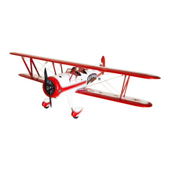
RED BARON PIZZA
SQUADRON'S STEARMAN
71. 5 i n ch e s .
" Graphics and specifications may change without notice " .
Code: SEA277
Specifications:
Wingspan---------------71.5 in (181.6 cm).
Wing area---------------1438.4 sq.in ( 92.8 sq.dm).
Weight-------------------13.9 lbs (6.0- 6.3 kg).
Length-------------------53.5 in (136 cm).
Engine-------------------20cc gasoline.
Radio--------------------5 channels with 6 servos.
1
Advertisement
Table of Contents

Summary of Contents for RED BARON PIZZA SQUADRON’S STEARMAN
- Page 1 A S S E M B L Y M A N U A L RED BARON PIZZA SQUADRON’S STEARMAN 71. 5 i n ch e s . “ Graphics and specifications may change without notice ” . Code: SEA277 Specifications: Wingspan---------------71.5 in (181.6 cm).
-
Page 2: Kit Contents
STEARMAN 71.5 inches Instruction Manual. INTRODUCTION. Thank you for choosing the STEARMAN 71.5 inches ARF by SG MODELS . The STEARMAN 71.5 inches was designed with the intermediate/advanced sport flyer in mind. It is a semi scale airplane which is easy to fly and quick to assemble. The airframe is conventionally built using balsa, plywood to make it stronger than the average ARF, yet the design allows the aeroplane to be kept light. -
Page 3: Hinging The Aileron
KIT CONTENTS. HINGING THE AILERON. SEA277 STEARMAN 71.5 inches Note : The control surfaces, including the ai- 1. Fuselage lerons, elevators, and rudder, are prehinged 2. Upper wing set with hinges installed, but the hinges are not 3. Lower wing set glued in place. - Page 4 STEARMAN 71.5 inches Instruction Manual. 8) After both ailerons are securely hinged, 4) Deflect the aileron and completely satu- firmly grasp the wing panel and aileron to rate each hinge with thin C/A glue. The ailer- make sure the hinges are securely glued and ons front surface should lightly contact the cannot be pulled out.
-
Page 5: Installing The Aileron Servos
INSTALLING THE AILERON SERVOS. 3) Apply 2-3 drops of thin C/A to each of the mounting holes. Allow the C/A to cure without using accelerator. C/A glue 4) Use dental floss to secure the connec- Because the size of servos differ, you tion so they cannot become unplugged. -
Page 6: Aileron Pushrod Installation
STEARMAN 71.5 inches Instruction Manual. C/A glue 8) Set the aileron hatch in place and use a 7) Remove the string from the wing at the Phillips screw driver to install it with four servo location and use the tape to attach it wood screws. -
Page 7: Installing The Fuselage Servos
THROTTLE SERVO ARM INSTALLATION. Install adjustable servo connector in the 55mm servo arm as same as picture below: Loctite secure. Adjustable servo M3 lock nut. M3 clevis. connector. Servo arm. Throttle servo arm. Elevator servo arm. Rudder servo arm. INSTALLING THE FUSELAGE SERVOS. Elevator servo arm. - Page 8 STEARMAN 71.5 inches Instruction Manual. Switch. INSTALLING THE ENGINE SWITCH. Trim and cut. Switch. INSTALLING THE MAIN LANDING GEAR TO FUSELAGE.
- Page 9 Thread a mounting screw into each of the holes to cut threads in the surround- ing wood. Apply a small amount of thin 3x15mm CA to harden the threads make by the screws. Position the landing gear so it rakes forward. Use the screws and land- ing gear straps to secure the landing gear to the bottom of the fuselage.
- Page 10 STEARMAN 71.5 inches Instruction Manual. M3x10mm...
- Page 11 M3x10mm...
-
Page 12: Installing The Stopper Assembly
STEARMAN 71.5 inches Instruction Manual. M4x5mm Collar. INSTALLING THE STOPPER ASSEMBLY. Collar. 1) Using a modeling knife, carefully cut off the rear portion of one of the 3 nylon tubes leaving 1/2” protruding from the rear of the stopper. This will be the fuel pick up tube. -
Page 13: Fuel Tank Installation
6) When satisfied with the alignment of the stopper assembly tighten the 3 x 20mm ma- chine screw until the rubber stopper expands and seals the tank opening. Do not over- tighten the assembly as this could cause the tank to split. FUEL TANK INSTALLATION. -
Page 14: Engine Mount Installation
STEARMAN 71.5 inches Instruction Manual. Blow through one of the lines to en- sure the fuel lines have not become kinked inside the fuel tank compartment. Air should flow through easily. ENGINE MOUNT INSTALLATION. 1) Locate the items necessary to install the engine mount included with your model. -
Page 15: Mounting The Engine
MOUNTING THE ENGINE. 1) Position the engine with the drive washer (145mm) forward of the firewall as shown. Machine screw M4x30mm 4) On the fire wall has the location for the throttle pushrod tube (pre-drill). 5) Slide the pushrod tube in the firewall 145mm and guide it through the fuel tank mount. - Page 16 STEARMAN 71.5 inches Instruction Manual. 8) Reinstall the servo horn by sliding the connector over the pushrod wire. Cent- er the throttle stick and trim and install the servo horn perpendiular to the servo center line. 9) Move the throttle stick to the closed po- sition and move the carburetor to closed.
- Page 17 DUMMY ENGINE. COWLING. Epoxy 1) Tape the cowl to the fuselage using low-tack tape. 2) Use a drill and drill bit to drill the holes for the cowl mounting screws. Make sure the cowl position is correct before drill- ing each hole.
- Page 18 STEARMAN 71.5 inches Instruction Manual. ELECTRIC POWER CONVERSION. 1) Locate the items neccessary to install the electric power conversion included with your model. 3x10mm Because of the size of the cowl, it may be nec- essary to use a needle valve extension for the high speed needle valve.
- Page 19 Then, use 5.5mm drill bit to enlarge the holes on the electric motor box. 5.5mm M4x20mm Blind nut. 4) Attach the motor to the front of the electric motor box using four 4mm blind nut, four M4x20mm hex head bolts to se- cure the motor.
- Page 20 STEARMAN 71.5 inches Instruction Manual. Balsa stick. Epoxy 5) Attach the speed control to the side of the motor box using two-sided tape and tie wraps. Connect the appropriate leads from the speed control to the mo- tor. Make sure the leads will not interfere with the operation of the motor.
-
Page 21: Installing The Spinner
INSTALLING THE SPINNER. INSTALL ELEVATOR CONTROL HORN. Install the spinner backplate, propeller and spinner cone. Fiberglass control horn The propeller should not touch any Epoxy. part of the spinner cone. If it does, use a sharp modeling knife and carefully trim away the spinner cone where the propel- ler comes in contact with it. - Page 22 STEARMAN 71.5 inches Instruction Manual. 2) Using a modeling knife, carefully re- move the covering at mounting slot of horizontal stabilizer ( both side of fuse- lage). Trim and cut When cutting through the covering to remove it, cut with only enough pressure to only cut through the covering itself.
-
Page 23: Hinging The Rudder
Epoxy. HINGING THE RUDDER. Glue the two rudder hinges in place us- ing the same techniques used to hinge the ailerons. Rudder fiberglass control horn. INSTALLING VERTICAL STABILIZER INSTALL RUDDER CONTROL HORN. Repeat steps to install the rudder control horn as same as steps done for ailerons. 1) Using a modeling knife, remove the covering from over the precut hinge slot cut into the lower rear portion of the fu-... -
Page 24: Elevator Pushrod Installation
STEARMAN 71.5 inches Instruction Manual. 5) When you are sure that everything is aligned correctly, mix up a generous amount of Flash 30 Minute Epoxy. Ap- ply epoxy to the bottom and top edges of the filler block. Set the stabilizer in place and realign. -
Page 25: Rudder Pushrod Installation
4) Elevator and rudder pushrods assem- RUDDER PUSHROD bly as pictures below. INSTALLATION. Repeat steps as same as steps done for elevator. 530mm 543mm M2 clevis. M2 lock nut. M2 clevis. M2 lock nut. -
Page 26: Mounting The Tail Wheel
STEARMAN 71.5 inches Instruction Manual. MOUNTING THE TAIL WHEEL. Locate items necessary to imstall tail gear. Metal clevis. 482mm Nose wheel steering arm. M2 lock nut. M2 clevis. - Page 27 C/A glue. INSTALL BRACING WIRE AND METAL BRACKET AT THE TAIL. TOP VIEW. 3x20mm 3x25mm 3x20mm...
- Page 28 STEARMAN 71.5 inches Instruction Manual. BOTTOM VIEW 3x15mm...
-
Page 29: Cabane Strut Installation
3x12mm 2) Place the cabane struts in position, not- ing their position as shown in the photo. Loosely install the four M3 x 12 socket head machine screws and M3 washers. Leave the hardware loose so the struts can be positioned while installing the upper wing center rib. - Page 30 STEARMAN 71.5 inches Instruction Manual. ATTACHMENT WING- FUSELAGE. Attach the aluminium tube into fuselage. Wing tube. 3) Place the upper center wing rib in position on the cabane struts. Start the M3 x 12 socket head machine screws and M3 washers that secure the rib to the cabane struts.
- Page 31 Insert two upper wing panels as pictures below. 2) Attach the two wing struts to the top of lower wing pant using an M3x12mm nachine screw and M3 washers. 4x12mm M3x12mm INSTALLATION WING STRUTS. 1) Loacte the items for this section of the manual.
- Page 32 STEARMAN 71.5 inches Instruction Manual. M3x12mm At this time, exact position of the end is set, please Use a 2.5mm hex wrench to slowly tighten the hardware securing the cabane struts in position on the fuselage. Again, make sure to use threadlock on all the fasteners to prevent them from vibrat- ing loose.
-
Page 33: Installation Cable
INSTALLATION CABLE. 1) Prepare one end of the cable by at- taching a cable end using a copper crimp. Thread a nut, then a clevis, on the cable end as shown. Prepare only one end of each cable at this time. Crimp M3 clevis Metal Cable. - Page 34 STEARMAN 71.5 inches Instruction Manual. Using the transport frames allow the re- moval of the wings without the need to remove the aileron linkage and the inter- plane strut between the top and bottom wings. INSTALLATION PILOT AND WINDSHIELD. 1) Locate items necessary to install pilot and windshield.
- Page 35 Epoxy. Epoxy. 4) Position the windshield onto the fuse- lage. Trace around the windshield onto the fuselage using a felt-tipped pen. Cut and remove the covering from between the lines drawn, and glue the windshield to the fuselage using epoxy or a special canopy glue.
- Page 36 STEARMAN 71.5 inches Instruction Manual. BALANCING. APPLY THE DECALS. 1) If all the decals are precut and ready to 1) It is critical that your airplane be stick. Please be certain the model is clean balanced correctly. Improper balance will and free from oily fingerprints and dust.
-
Page 37: Control Throws
*If possible, first attempt to balance the CONTROL THROWS. model by changing the position of the re- ceiver battery and receiver. If you are un- Ailerons: Rudder: able to obtain good balance by doing so, High Rate : High Rate : then it will be necessary to add weight to Up : 25 mm Right : 30 mm... -
Page 38: Flight Preparation
If it does not, flip the servo reversing excessive vibration which could lead switch on your transmitter to change to engine and/or airframe failure. the direction. We wish you many safe and enjoyable flights with your inches. RED BARON PIZZA SQUADRON’S STEARMAN 71.5... - Page 39 If you have any queries, or are interested in our products, please feel free to contact us Factory : 12/101A - Hamlet 4 - Le Van Khuong Street - Dong Thanh Ward - Hoc Mon District - Ho Chi Minh City - Viet Nam. Office : 62/8 Ngo Tat To Street - Ward 19 - Binh Thanh District - Ho Chi Minh City - Viet Nam Phone : 848 - 37114542 or 848- 36018777...
Need help?
Do you have a question about the SQUADRON’S STEARMAN and is the answer not in the manual?
Questions and answers