Table of Contents
Advertisement
Advertisement
Table of Contents

Related Manuals for Bristan Artisan Evo


Summary of Contents for Bristan Artisan Evo
- Page 1 Installation Instructions and User Guide Artisan Ev Digital Electronic Mixer Shower Models covered: ARDE SHCCF W & ARDE SHCCF B Please keep this booklet for future reference. Installer, when you have read these instructions please ensure you leave them with the user.
-
Page 2: Table Of Contents
Welcome to your new Bristan Digital Electronic Mixer Shower, featuring a contemporary design, wireless electronic controller and digital mixing unit. Bristan’s Digital Electronic Mixer Shower has been designed to be easy to install and use. It has also been designed and tested in the UK to all of the relevant British Standards. -
Page 3: Important Safety Information
Important Safety Information • Please read these instructions thoroughly and retain for future use. • All products manufactured and supplied by Bristan are safe provided they are installed, used correctly and receive regular maintenance in accordance with these instructions. • If you are in any doubt about your ability to install this product safely you must employ the services of an experienced qualifi... -
Page 4: General Information
General Information • Remove all packaging and check the contents for damage before starting any installation. • Fitting isolation valves to the inlet feeds is required as close as is practical to the inlet connections for ease of maintenance. • Always switch off the power at the consumer unit and isolate the electrical supply before making any electrical connections or if you have to remove the cover of the Mixing Valve. -
Page 5: Pack Contents
Pack Contents & Tools Required Wall Plugs x7 Shroud x1 Batteries x2 Wireless Controller x1 Arm x1 Remote Control Screw x3 Rose x1 Sealing Washer x1 Mixing Valve x1 Mixing Valve Screw x4 Tools Required - Not supplied Flat Head Screw Drill Suitable Drill bit Phillips Screwdriver... -
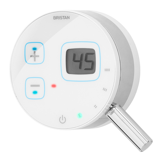
Page 6: Product Features
Product Features 1. Temperature control Press to increase the temperature up to a factory set maximum of 48ºC (the maximum temperature can be overridden, see Maximum Temperature Setting on page 19). Press to decrease the temperature down to a minimum of 35ºC. 2. -
Page 7: Specifi Cations
Specifi cations Water Supply Requirements Inlet connections: 1/2” BSP with 70mm between centres. Operating pressure range: Min. 0.5 bar - Max. 5.0 bar For optimum performance a minimum dynamic working pressure of 1.0 bar is required. Minimum static pressure: 0.5 bar Maximum static pressure: 10.0 bar Supply requirements: Minimum cold water supply temperature: 5ºC. -
Page 8: Dimensions
Dimensions (mm) G1/2 Need help? Give us a call on 0844 701 6273 and speak to one of our trained advisers. -
Page 9: Installation Requirements
Installation Requirements Positioning the mixing valve The Mixing Valve can be positioned on either a wall surface or fl at on the fl oor. (Refer to the diagrams for the correct Flat on the fl oor orientation of the Mixing Valve). The Mixing Valve can be installed in either an airing cupboard, loft space or under the bath. -
Page 10: Water Requirements
Installation Requirements Water Requirements greater. If the fi tting cannot be installed as indicated it shall be installed with a This fi tting needs to be installed in backfl ow prevention arrangement suitable accordance with the following Installation for the Fluid Category. Requirements and Notes (IRN) to ensure they meet the requirements of the Water If the shower is to be installed in a hard... -
Page 11: Electrical Requirements
Installation Requirements Note: If a showerhead can sit within a This product must be connected to a fused bath, basin or shower tray, Water spur with double-pole isolation and a 3A Regulations stipulate a double check valve fuse. must be fi tted in the supply pipe work to It is recommended that a residual current prevent back siphonage*. -
Page 12: Installation
Installation - Mixing Valve Fixing the Mixing Valve to the fl oor / wall Fixing points Please refer to Positioning the Mixing Valve on page 9 before starting any installation. The Mixing Valve needs to be installed on either a fl at fl oor or a wall surface. Position the Mixing Valve on the fl... -
Page 13: Water Connections
Installation - Water Connections Plumbing Connections Warning: Do not solder within 300mm of the Mixing Valve or allow solder or fl ux to fall onto the casing. Important: An additional independant stop valve complying with the current water regulations must be fi tted in the mains water supply as a means of isolating the supplys to the Mixing Valve for servicing and / or maintenance work. -
Page 14: Electrical Connections
Installation - Electrical Connections Electrical Connections • The wire which is coloured green and The electrical installation must be carried yellow must be connected to the out in accordance with the current I.E.E terminal in the connection unit which Wiring Regulations (BS 7671) and Building is marked with the letter E or by the Regulations (Part P). -
Page 15: Fitting The Wireless Controller
Installation - Wireless Controller Fitting the Wireless Controler Remove the locking ring and wall bracket from the wireless controller by twisting the locking ring clockwise. Position the wall bracket onto the fi nished wall surface and mark the fi xing holes. Drill holes at the marked positions on the Wall wall surface using a suitable drill bit for... -
Page 16: Shower Arm & Rose
Installation - Ceiling Fed Arm & Rose Fitting the Ceiling Fed Arm & Rose Pipework secured to the top of a beam / Before proceeding with fi tting the ceiling joist fed arm and rose, suitable 15mm supply pipework must be installed above the Pipe Clip 15mm Pipework ceiling / in the loft area, from the Mixing... - Page 17 Installation - Ceiling Fed Arm & Rose Drill a 25-30mm hole in the ceiling / plasterboard at the required position for the shower arm. Shroud Screw the shroud onto the top thread of the arm. Place the top thread of the arm through the hole in the ceiling / plasterboard and secure in place using a G1/2 backnut.
-
Page 18: Commissioning
Commissioning - Wireless Connection Wireless Initialisation & Pairing of the Additionally, it may also be necessary remote control to mixing valve to perform the Initialisation and Pairing For the wireless communication to work, (Steps 2 & 3), if: the Remote Control needs to be initialised - You purchase a separate / and paired with the Mixing Valve. -
Page 19: Maximum Temperature Setting
Commissioning - Max Temp Setting 2.4. Press the Temp up button ten 2. Locate the block of four switches times to increment the fl ashing number marked SW1 on the circuit board. Position from “0” to “9”, and then to steady-state the individual switches as per the “2”... -
Page 20: Water / Plumbing Connections
Commissioning - Functional Testing Checking Water / Plumbing Connections 7. Once the pulsing stops, turn the Before using the shower for the fi rst time Controller Off. the installer needs to check that the 8. To resume normal showering, simply water/plumbing connections are correct. -
Page 21: Operating The Shower
Operating the Shower Please ensure the commissioning procedure has been carried out. If you did not fi t this shower yourself and you are about to use it for the fi rst time, check with the installer to ensure they have run the commissioning procedure as described on pages 19-21. -
Page 22: Maintenance
Filter Washer Cleaning the Showerhead Your Bristan showerhead has rub-clean nozzles for easy cleaning. Simply rub your Insert fingers across the rubber spray jets regularly and before you turn the shower Cleaning the Filters on to remove any scale or debris. - Page 23 Maintenance Battery Replacement Important: Do not use re-chargeable The Wireless Controller is powered by two batteries. AA batteries which are designed to last approximately 1 year based on average showering usage before they need replacing. When the batteries run low and require replacing, the red low battery LED on the front face of the display will fl...
-
Page 24: Maintenance
Maintenance Disposal and Recycling health and the environment. For more information about where you can drop End of Product Life off your waste equipment for recycling, When this appliance has reached the end please contact your local council office, of its serviceable life, it should be your household waste disposal service disposed of in a safe manner, in or the shop where you purchased the... -
Page 25: Troubleshooting
Wireless Controller to the Mixing Valve in Commissioning Section (pag- es 18-20). E2 displayed Main unit has developed a Call Bristan Customer Servic- fault. es on 0844 701 6273. E3 displayed Hot water is isolated or has Check the hot water supply is insuffi... - Page 26 Troubleshooting Symptom Cause Remedy No or low water fl ow Batteries low / run out in Replace batteries, refer to Wireless Controller. maintenance section (page 23). Outlet is blocked. Check outlet and shower rose for any blockages. Partially closed stop or service Open stop or service valve.
-
Page 27: Spare Parts
Spare Parts Part No. Description Parts List Quantity ARDE WC W Controller (White) incl. fi xings White Controller x1, Fixings x3 ARDE WC B Controller (Black) incl. fi xings Black Controller x1, Fixings x4 EMV WSO Mixing Valve incl. fi xings Mixing Valve x1, Fixings x4 NRV 08400A NRV x1... -
Page 28: Notes
Notes Please use this space to add any notes you or your installer may have regarding the plumbing system / installation of this product. Need help? Give us a call on 0844 701 6273 and speak to one of our trained advisers. -
Page 29: Notes
Notes Please use this space to add any notes you or your installer may have regarding the plumbing system / installation of this product. Need help? Give us a call on 0844 701 6273 and speak to one of our trained advisers. -
Page 30: Guarantee
Guarantee At Bristan, we want to make things as • Repair under this guarantee does not easy as possible for our customers. That’s extend the original expiry date. The why we design products that are easy to guarantee on any replacement parts or fit and use, and that are quality tested to product ends at the original expiry date. - Page 31 ‘phone or with a spare part, then we’ll guarantee period, contact Bristan Care send out one of our Bristan Care Customer Service on 0844 701 6273 with engineers to take a look. Bristan Care...
- Page 32 Part Number: FI: ARDE SHCCF Issue: D2 Useful contact details: Customer Service: 0844 7016273 Bristan Group Ltd, Customer Service Email: Birch Coppice Business Park Customercare@bristan.com Dordon Tamworth Customer Service Fax: Staffordshire 0844 7016275 B78 1SG Reception: Web: www.bristan.com 0844 7016274 Email: enquire@bristan.com...
Need help?
Do you have a question about the Artisan Evo and is the answer not in the manual?
Questions and answers