
Related Manuals for Kramer MV-5


Summary of Contents for Kramer MV-5
- Page 1 K R A ME R E LE CT R O N IC S L TD . USER MANUAL MODEL: MV-5 5 Channel Multiviewer P/N: 2900-300134 Rev 5...
-
Page 3: Table Of Contents
Defining the MV-5 5 Channel Multiviewer Installing in a Rack Connecting the MV-5 5 Channel Multiviewer Connecting to the MV-5 Using the RS-232 Connection Connecting to the MV-5 Using the RS-485 Connection Connecting to the MV-5 Using Ethernet Configuring and Operating the MV-5 Locally... - Page 4 Figure 16: Connection Method Window Figure 17: Windows Position Figure 18: Switch Buttons Figure 19: Layer Order Figure 20: Switching an Input to a Window Figure 21: Windows Setup Window Figure 22: Input Button Properties Window MV-5 - Introduction...
-
Page 5: Introduction
Scan Converters and Scalers; GROUP 8: Cables and Connectors; GROUP 9: Room Connectivity; GROUP 10: Accessories and Rack Adapters and GROUP 11: Sierra Video Products. Congratulations on purchasing your Kramer MV-5 5 Channel Multiviewer which is ideal for: Professional broadcasting and production studios ... -
Page 6: Getting Started
Avoid interference from neighboring electrical appliances that may adversely influence signal quality Position your MV-5 away from moisture, excessive sunlight and dust This equipment is to be used only inside a building. It may only be connected to other equipment that is installed inside a building. -
Page 7: Recycling Kramer Products
Accessory to Medical Equipment (IEC 60601-1) In the modern medical environment remote access is essential, for example, to transfer clinical data between doctors and to train to medical students. The MV-5 is certified according to the IEC 60601-1-2, Clause 2.1.3, Medical Electrical... -
Page 8: Overview
Overview The MV-5 is a versatile, high-performance video and graphic multi-viewer for DVI signals, SD and HD analog signals up to 1920x1200@60Hz, and SDI signals up to 3G HD-SDI. The device can window up to four sources (plus a background) in any layout and output the image as SDI, DVI, component and composite video signals. - Page 9 A front panel lock button The MV-5 is housed in a 19" 2U rack mountable enclosure and is fed from a 100-240 VAC universal switching power supply. You can control the MV-5 using the front panel buttons, or remotely via: ...
-
Page 10: Defining The Mv-5 5 Channel Multiviewer
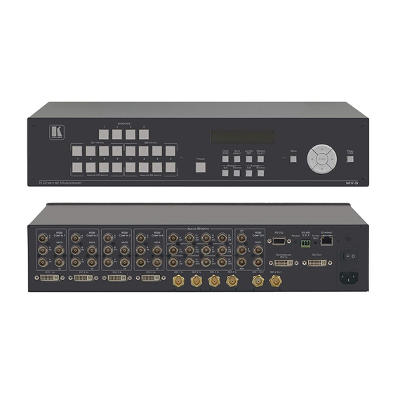
Defining the MV-5 5 Channel Multiviewer Figure 1 defines the front panel of the MV-5. Figure 1: MV-5 5 Channel Multiviewer Front Panel Feature Function DVI INPUTS 1~4 Buttons Press to select one of the DVI sources 7 WINDOWS 1~4 Buttons... - Page 11 Feature Function LAYERS DEF Button Press to set the order of priority of the window layers MENU Button Press to enter the configuration menu. When the menu is displayed, press to exit one level (see Section 7 ENTER Navigation Pad Press Enter to enter the sub-menu or accept a parameter value.
-
Page 12: Figure 2: Mv-5 5 Channel Multiviewer Rear Panel
Figure 2 defines the rear panel of the MV-5. Figure 2: MV-5 5 Channel Multiviewer Rear Panel Feature Function IN 1 Connect to an analog HD video source IN 2 Connect to an analog HD video source RGB BNC Connectors... - Page 13 Feature Function DVI IN 1 ~ 4 DVI Connectors Connect to the DVI video sources (1 to 4) SDI IN 1 ~ 4 BNC Connectors Connect to the SDI video sources (1 to 4) SDI OUT 1 and 2 BNC Connectors Connect to the SDI video acceptors (1 and 2) ...
-
Page 14: Installing In A Rack
Installing in a Rack This section provides instructions for rack mounting the unit. MV-5 - Installing in a Rack... -
Page 15: Connecting The Mv-5 5 Channel Multiviewer
Connecting the MV-5 5 Channel Multiviewer You can use your MV-5 to switch four of the 16 inputs (four HD, four SD, four DVI, and four SDI), to four outputs (two SDI, a DVI and an HD). The four inputs are combined in a customizable format and then combined with a user-selectable background. -
Page 16: Figure 3: Connecting The Mv-5 5 Channel Multiviewer
Figure 3: Connecting the MV-5 5 Channel Multiviewer To connect the MV-5 5 Channel Multiviewer as illustrated in the example in Figure 1. Connect up to four HD video sources, (for example, component video players) to the RGB IN BNC connectors. - Page 17 9. If required, connect a controller to the: 6 RS-232 port (see Section 6 RS-485 port (see Section 6 Ethernet connector (see Section 10. Connect the power cord and power the device on. MV-5 - Connecting the MV-5 5 Channel Multiviewer...
-
Page 18: Connecting To The Mv-5 Using The Rs-232 Connection
6.2.1 Connecting via RS-485 You can operate the MV-5 via the RS-485 port from a distance of up to 1200m (3900ft) using any device equipped with an RS-485 port (for example, a PC). To connect a device with an RS-485 port to the MV-5: ... -
Page 19: Figure 4: Local Area Connection Properties Window
6.3.1 Connecting the Ethernet Port Directly to a PC You can connect the Ethernet port of the MV-5 directly to the Ethernet port on your PC using a crossover cable with RJ-45 connectors. This type of connection is recommended for identifying the MV-5 with the factory configured default IP address. -
Page 20: Figure 5: Internet Protocol Version 4 Properties Window
6. Select Use the following IP Address for static IP addressing and fill in the details as shown in Figure You can use any IP address in the range 192.168.1.1 to 192.168.1.255 (excluding 192.168.1.39) that is provided by your IT department. MV-5 - Connecting the MV-5 5 Channel Multiviewer... -
Page 21: Figure 6: Internet Protocol Properties Window
6.3.2 Connecting the Ethernet Port via a Network Hub or Switch You can connect the Ethernet port of the MV-5 to the Ethernet port on a network hub or using a straight-through cable with RJ-45 connectors. MV-5 - Connecting the MV-5 5 Channel Multiviewer... -
Page 22: Configuring And Operating The Mv-5 Locally
Section 7 Operating the MV-5 using the front panel buttons (see .1.8) When the MV-5 is powered on, the device performs a self test. If the test is successful, the Window/Input list is displayed, an example of which is shown below. - Page 23 Window button lights only if the Window priorities were not specifically changed while in the Layer Def mode. Using the Layer Def button, you can then set the priority of any layer (0 to make it invisible. MV-5 - Configuring and Operating the MV-5 Locally...
-
Page 24: Configuring The Mv-5 Using The Menu
Input Signal Status Sub-menu (see Section .1.6) 7 System Parameters Sub-menu (see Section .1.7) Section 7 Save Image Sub-menu (see .1.8) Section 7 Recall Image Sub-menu (see .1.9) MV-5 - Configuring and Operating the MV-5 Locally... - Page 25 3. Use the left (◄) and right (►) buttons to select the required preset to which you want to save the current setup. 4. Press Enter. The current setup is saved and the display changes to indicate the current setup. MV-5 - Configuring and Operating the MV-5 Locally...
- Page 26 2. Use the up (▲) and down button (▼) to navigate to the Input Configuration sub-menu. 3. Press Enter. The Assign Analog SD Button 1 format is displayed. 4. Use the up (▲) and down button (▼) to navigate to the HD Input 2 Format selection. MV-5 - Configuring and Operating the MV-5 Locally...
- Page 27 0 to 255 R-value: color value Default—0 BackGround Color Sets the background 0 to 255 G-value: green color value Default—0 BackGround Color Sets the background blue 0 to 255 B-value: color value Default—0 MV-5 - Configuring and Operating the MV-5 Locally...
- Page 28 LCD. If the DVI output of the MV-5 is connected to a video acceptor that does not support HDCP, then all output formats that do not carry the HDCP protected input signal are available, but not those outputs which do carry the HDCP protected signal (for example, DVI, SDI and Analog).
- Page 29 DVI output is turned off and simultaneously all DVI inputs become HDCP non-capable. In this case, the responsibility for content protection remains completely on the source, as it sees its video acceptor (that is, the MV-5 DVI input) as not being HDCP capable. All other outputs (SDI and analog) are available.
- Page 30 4. Use the up (▲) and down button (▼) to navigate to the BackGrnd MODE: option. 5. Use the left (◄) and right (►) buttons to select the DVI INPUT BACKGROUND option. 6. Press Enter. The current setup is saved. MV-5 - Configuring and Operating the MV-5 Locally...
- Page 31 Sets the image transparency for the 0 to 255 Transparency: selected Window Default—0 Test Sets the test signal for the selected No Test Signal, Color Bars window 100%, Split Bars 100%, Ramp 100% MV-5 - Configuring and Operating the MV-5 Locally...
- Page 32 5. Use the up (▲) and down button (▼) to navigate to the Color R-Value option. 6. Use the left (◄) and right (►) buttons to select the red value. 7. Press Enter. The current setup is saved. MV-5 - Configuring and Operating the MV-5 Locally...
- Page 33 Enables and disables automatic IP OFF, ON addressing Default: OFF Ethernet UDP Port Number Sets the TCP UDP port number. Default: 50000 One item for three lowest significant digits; second item for 2 highest significant digits MV-5 - Configuring and Operating the MV-5 Locally...
- Page 34 Use the Save Image sub-menu to select a window, from which to capture the currently frozen image; and to select a file name to save this image. The MV-5 has four flash memory locations that store four different image files with arbitrary resolution (up to 1920x1200).
- Page 35 16 sec with one PAL resolution file, 30 sec with one 1920x1080 file, to 110 sec with all windows and background recalling simultaneous HD images. All recalled images can be adjusted (contrast, color, sharpness and so on) or resized and positioned, or used for chroma-key layer. MV-5 - Configuring and Operating the MV-5 Locally...
- Page 36 ATTENTION! To reload the image from the same file repeatedly, select “NO FILE” (press Enter) and then reselect the file. To recall a different image file, do not use the “NO FILE” option. MV-5 - Configuring and Operating the MV-5 Locally...
-
Page 37: Operating The Mv-5 Using The Front Panel Buttons
The display changes to show the Window Configuration sub-menu. 9. Press Menu again to exit the menu. The display changes to show the default Window-Input configuration. Operating the MV-5 Using the Front Panel Buttons This section describes: Section 7 Assigning inputs to windows (see .2.1) - Page 38 There are two ways to change the windows size: Adjusting the horizontal and vertical window size separately (thereby possibly altering the window aspect ratio). Locking the aspect ratio and adjusting the horizontal and vertical sizes together. MV-5 - Configuring and Operating the MV-5 Locally...
-
Page 39: Figure 7: Image Position And Scaling Example
HD video format (16:9) on an SDTV monitor (4:3), set the aspect ratio to about 133%. The broad range of aspect ratio adjustment on the MV-5 allows for a wide range of different PC graphic input and output resolutions. - Page 40 250,300. The MV-5 ensures that the whole of the source (of size 750 by 400) is scaled to the required output (of size 250 x 300). To adjust the horizontal and vertical size of a window separately: Press the Window Size button.
- Page 41 (10 times the original Image size). If the window size or aspect ratio changes then the Image size changes in such a manner that the Image remains the same inside within the window. There are two ways to change the Image size and aspect ratio (Zoom): MV-5 - Configuring and Operating the MV-5 Locally...
- Page 42 PVW button can be used not only to see the cropping mask, but also to quickly revert to a full-screen in the window. The Crop PVW button must be pressed while the device is in Main mode. Pressing this button again returns the MV-5 to the initial windows Sizes and Positions.
- Page 43 The button no longer lights, the Image size and aspect ratio are set and the display returns to the Window/Input selection. Adjusting the Position of the Image Inside a Window – Panning 7.2.6 MV-5 - Configuring and Operating the MV-5 Locally...
- Page 44 4. Press the Freeze button again. The button no longer lights and the Image is no longer frozen. 5. If the Window Select button is lit, press the button to cancel the Window selection. MV-5 - Configuring and Operating the MV-5 Locally...
- Page 45 To reset the device to the factory default configuration: 1. Turn the device off. 2. Press and hold the Reset button on the rear panel of the device. 3. While holding the button depressed, turn the device on. MV-5 - Configuring and Operating the MV-5 Locally...
- Page 46 4. Hold the button depressed until the Window/Input is displayed. 5. Release the button. The configuration is reset to the factory default. MV-5 - Configuring and Operating the MV-5 Locally...
-
Page 47: Configuring And Operating The Mv-5 Remotely
The Quick Access Toolbar (see Section 8 Using the MV-5 Multiviewer Software (see Kramer offers free control software that enables you to operate the MV-5 remotely Section 1 via a PC or serial controller using serial commands (see 3.1). -
Page 48: The Multiviewer Main Window
Controller Software. Similarly, if a change is made in the Controller Software, the change is reflected almost immediately on the device. MV-5 - Configuring and Operating the MV-5 Remotely... -
Page 49: The Menu Bar
Stores the current configuration in a memory preset Recall Recalls the configuration from a memory preset Section 8 ABOUT Displays the Multiviewer Software and Kramer company details (see .2.6) 8.2.1 Setting the Background Color You can assign a preset or custom color to the background. -
Page 50: Figure 9: Background Color Window
You can set the image properties, such as, brightness, contrast and border color. To modify the image properties: 1. From the Menu bar, click Display > Image Properties. The Image Properties window appears as shown in Figure MV-5 - Configuring and Operating the MV-5 Remotely... -
Page 51: Figure 10: Image Properties Window
(Label Disabled, Black Window Label, White Window Label, Black Video Input Label, White Input Video Label) Label Position Sets the position of the label in the border, (Top left, top middle, top right, bottom left, bottom middle, bottom right) MV-5 - Configuring and Operating the MV-5 Remotely... -
Page 52: Figure 11: Advanced Properties Window
Sets the output when no input is present, (freeze last image, Blue screen, Black screen, Remove window) LCD Brightness Sets the brightness of the LCD backlighting Sleep Mode Brightness Sets the brightness of the LCD backlighting when the device is in sleep mode MV-5 - Configuring and Operating the MV-5 Remotely... - Page 53 From this window you can change the device name and its IP communication parameters. To change the device details: 1. From the Menu bar, click on Device. The Device Details window appears as shown in Figure MV-5 - Configuring and Operating the MV-5 Remotely...
-
Page 54: Figure 12: Device Details Window
8.2.6 Displaying the MV-5 Software Version Number To display the MV-5 Software version number: 1. From the Menu bar, click About. The About MV-5 Multiviewer Controller window appears as shown in Figure MV-5 - Configuring and Operating the MV-5 Remotely... -
Page 55: The Quick Access Toolbar
Update to implement the changes (see .4.5) Freezes and releases the top window Sets the visibility of the active window Sets the window zoom parameters Sets the chroma key properties Figure 15: Quick Access Toolbar Icons MV-5 - Configuring and Operating the MV-5 Remotely... -
Page 56: Figure 16: Connection Method Window
For a USB connection, select the required USB connection from the drop-down list 3. Click Connect. If the connection is successful, the main window shown in Figure 8 appears. If the connection is not successful, a Timeout error message appears. MV-5 - Configuring and Operating the MV-5 Remotely... -
Page 57: Using The Mv-5 Multiviewer Software
To change the position of a window: Click, hold and drag anywhere in the window 8.4.2 Window and Input Buttons The switching configuration can be modified by clicking on the Windows and Inputs buttons. MV-5 - Configuring and Operating the MV-5 Remotely... -
Page 58: Figure 18: Switch Buttons
Online in take mode—changes made in the application are only implemented on the device when the Update button is pressed MV-5 - Configuring and Operating the MV-5 Remotely... -
Page 59: Figure 19: Layer Order
The button changes to the Update button and the device is in off-line mode. 2. Initiate the required actions, such as, switching and layer order changes. 3. Press the Update button. The button changes to the Take button and all actions are executed. MV-5 - Configuring and Operating the MV-5 Remotely... -
Page 60: Figure 20: Switching An Input To A Window
Figure 20: Switching an Input to a Window 2. Click on the required Inputs button. The input is assigned to the previously selected window and the button changes to a solid color. MV-5 - Configuring and Operating the MV-5 Remotely... -
Page 61: Figure 21: Windows Setup Window
3. From the Connect to Input drop-down list, select the required input. 4. Click the Freeze icon to freeze this window. 5. Click the Visibility icon to modify the visibility of this window. MV-5 - Configuring and Operating the MV-5 Remotely... - Page 62 The Window setup is changed. 8.4.8 Changing Input Button Properties To change the properties of an input button: 1. Right-click on the relevant input button. The Input Properties window appears as shown in Figure MV-5 - Configuring and Operating the MV-5 Remotely...
-
Page 63: Figure 22: Input Button Properties Window
The icon image should be no larger than 32 x 32 pixels and one of the following formats: BMP, JPG, GIF, PNG, TIF, ICO. 4. Click OK. The input button characteristics are changed. MV-5 - Configuring and Operating the MV-5 Remotely... -
Page 64: Upgrading The Firmware
The firmware can be uploaded either using the Web pages (see .2.4) or by using the K-Upload Software. The instructions for using the K-Upload Software can be found in the “Upgrading the MV-5 Firmware Using the K-Upload Software” document MV-5 - Upgrading the Firmware... -
Page 65: Technical Specifications
0° to +40°C (32° to 104°F) TEMPERATURE: –40°C to +70°C (–40° to 158°F) STORAGE TEMPERATURE: HUMIDITY: 10% to 90%, RHL non-condensing 19” x 9.45” x 2U (W, D, H) DIMENSIONS: WEIGHT: 2.8kg (6.17lbs) approx. Power cord, rack ”ears” INCLUDED ACCESSORIES: MV-5 - Technical Specifications... -
Page 66: Default Communication Parameters
Default Communication Parameters RS-232 Baud Rate: 115,200 Data Bits: Stop Bits: Parity: None Command Format: ASCII Protocol example (Output 1 to Input 1): #AV 1>1<CR> Ethernet IP Address: 192.168.1.39 TCP Port #: 5000 UDP Port #: 50000 MV-5 - Default Communication Parameters... -
Page 67: Default Edid
Default EDID The MV-5 has a non-modifiable, preprogrammed EDID stored on each input. Monitor Model name....MV-5 Manufacturer..... KMR Plug and Play ID..KMR1200 Serial number.... 505-708980100 Manufacture date..2011, ISO week 255 Filter driver.... None ------------------------- EDID revision.... 1.3 Input signal type.. -
Page 68: Kramer Protocol 3000
Kramer Protocol 3000 The MV-5 can be operated using serial commands from a PC, remote controller or touch screen using the Kramer Protocol 3000. This section describes: 1 Kramer Protocol 3000 syntax (see Section 3.1) 1... - Page 69 Query sign '?' follows some commands to define a query request. Message closing character CR – For host messages; carriage return (ASCII 13) CRLF – For device messages; carriage return (ASCII 13) + line-feed (ASCII 10) MV-5 - Kramer Protocol 3000...
- Page 70 You can directly enter all commands using a terminal with ASCII communications software, such as HyperTerminal, Hercules, etc. Connect the terminal to the serial or Ethernet port on the Kramer device. To enter CR press the Enter key. ( LF is also sent but is ignored by command parser).
-
Page 71: Kramer Protocol 3000 Commands
Read saved preset list (see Note below) RESET Reset device Read device serial number UPGRADE Execute firmware upgrade VERSION? Read device firmware version 13.2.2 Device-Specific Commands Set Command syntax Y Control_Type=0, Function#, Param For example: #Y 0,212,1 Device response: ~id=01Y Control_Type=0,Function#,Param MV-5 - Kramer Protocol 3000... - Page 72 For example: ~01@Y 1,200,3 The following table lists the MV-5 “Y commands”. If a parameter in the table is given as multidimensional vector (for example, IN_FRMT[4] - has the dimension = 4), this signifies that there are four different parameters each of which reflect a state of the same feature for different inputs or different windows.
- Page 73 DVI input# is HDCP non-capable Additional parameter defines DVI Input. HDCP_IN[4] – for DVI background input Output Video OUT_RSL 480i/60 Resolution 576i/50 720p/50 720p/59 720p/60 1080i/50 1080i/59 1080i/60 1080p/23 1080p/24 1080p/25 1080p/29 1080p/30 1080p/50 1080p/59 1080p/60 1080sf/23 1080sf/24 MV-5 - Kramer Protocol 3000...
- Page 74 Normal windows size and position in the screen Top Layer window Image is fit in the screen Cropping The cropping border arises Preview Analog HD OUT_HD_FRMT RGBHV output format RGBS RGsB YUV bi-sync YUV tri-sync MV-5 - Kramer Protocol 3000...
- Page 75 HDCP on Output "OFF" DVI OUTPUT OUT_STATUS Output forced to non-encrypted HDCP (NO HDCP) STATUS MV-5 tries to set HDCP link, but acceptor don't support HDCP. Encryption turn OFF HDCP active (monitor supports HDCP) DVI output HDCP is ACTIVE, but SDI and...
- Page 76 1080i/50 window 4 INP_RES[4] - 1080i/59 reflects background 1080i/60 input status 1080p/23 1080p/24 1080p/25 1080p/29 1080p/30 1080p/50 1080p/59 1080p/60 1080sf/23 1080sf/24 1080sf/25 1080sf/29 1080sf/30 640x480/60 640x480/72 640x480/75 640x480/85 800x600/60 800x600/72 800x600/75 800x600/85 1024x768/60 1024x768/70 1024x768/75 MV-5 - Kramer Protocol 3000...
- Page 77 H and V window sizes are defined independently by WSZ_H and WSZ_V enable Parameter WSZ_H affects simultaneously H and V window size, but the relation between H and V sizes is defined by next parameter: WIN_ASP MV-5 - Kramer Protocol 3000...
- Page 78 H ZOOM = 1000% Image V size IMSZ_V[4] [0:900] Defines V size of image relatively window V size (i.e. V ZOOM) Step = 1% If IMSZ_V = 0 then image is exactly fits to window height. MV-5 - Kramer Protocol 3000...
- Page 79 (100%) Window image COLOR[4] If COLOR = 0 then default color 100:50] color(100%). If SHARP = 0 - no sharpness, Window image SHARP[4] [0:15] if = 15, then max sharpness 150% sharpness Step = 10% MV-5 - Kramer Protocol 3000...
- Page 80 Bottom center location Bottom right location Top left Top center Top right TEST signal TEST[4] No TEST signal; Input signal is selected for window, if available COLOR BARS 100% Split COLOR BARS 100% Y RAMP 100 % MV-5 - Kramer Protocol 3000...
- Page 81 Freeze last picture LCD brightness LCD_BRGHT [-100:0] LCD brightness while keyboard activated If LCD_BRGHT=0 - brightness = 100% LCD brightness in sleep mode (after 2 min LCD brightness LCD_SLEEP [-100:0] keyboard is non-activated) in sleep MV-5 - Kramer Protocol 3000...
- Page 82 Description Function # Parameter Value Notes Panel Lock PLOCK No Lock FP Lock Panel MV-5 - Kramer Protocol 3000...
- Page 84 For the latest information on our products and a list of Kramer distributors, visit our Web site where updates to this user manual may be found. SAFETY WARNING Disconnect the unit from the power supply before opening and servicing 2900- 300134...
Need help?
Do you have a question about the MV-5 and is the answer not in the manual?
Questions and answers