
Related Manuals for PTI security systems APEX

Summary of Contents for PTI security systems APEX
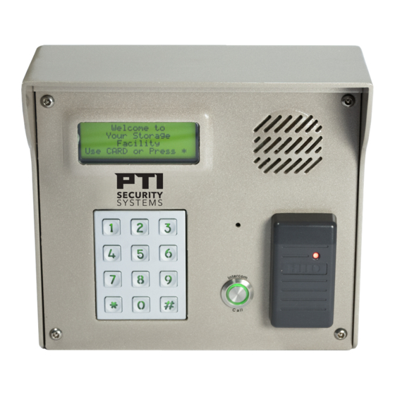
- Page 1 APEX Access Device Installation and Operation Manual www.ptisecurity.com 800.331.6224 114A3863 Rev E - July 2017...
- Page 2 APEX Access Device Thank you for purchasing the APEX Keypad Access Device. While every effort has been made to ensure the accuracy of the information in this document, PTI Security Systems assumes no liability for any inaccuracies contained herein. We reserve the right to change the information contained herein at any time and without notice.
- Page 3 PTI Security Systems products are installed. PTI Security Systems does not authorize the use of its products in applications affecting life safety.
-
Page 4: Table Of Contents
APEX Access Device Contents Technical Specifications ............Installation ................Placing APEX Devices ........... Mounting Access Devices ..........Installing APEX Access Devices ........Installation Instructions ..........Connecting Additional Features ......... Testing the Keypad ............. Operation ................Input/Output Descriptions ......... Using Extended Door Controls ........ -
Page 5: Technical Specifications
APEX Access Device Technical Specifications Input Power: Voltage: 12 – 18 VAC or DC Current Consumption: 300mA Maximum Relay Specifications: Maximum Switching Voltage: 30 VAC / 30VDC Maximum Switching Current: AC: 10A (NO) / 3A (NC) DC: 5A (NO) / 3 A (NC) -
Page 6: Installation
For drive up access, install the device where it can be reached from a vehicle’s driver door. If the APEX is used for walk up access, install it where it can be accessed by a person on foot. -
Page 7: Mounting Access Devices
Walk Up Accessibility When the APEX is used for walk up access, it can be mounted on a stand or attached to a wall. It can also be surface mounted so that it protrudes from the wall. - Page 8 APEX Access Device Note: If the APEX is installed on an exterior wall, seal the contact point between the housing and the wall with a silicone sealant rated for outdoor use. This prevents moisture and insects from getting into the housing.
- Page 9 This box mount must be ordered separately. With a normal APEX mount, a standing person may not be able to see the display. Mounting height varies from 42” – 58”...
- Page 10 3/4 of the way with concrete to create a solid barrier. The entire pipe and bollard are then painted to match the facility. Contact PTI Security Systems for full measured installation plans and instructions. Wall Mount Gooseneck A wall mount gooseneck allows the keypad to be mounted on a wall.
- Page 11 ‘5’ button on the touchpad for vehicular access. If the APEX is installed on an exterior wall, seal the contact point between the housing and the wall with a silicone sealant rated for outdoor use. This prevents moisture and insects from getting into the housing.
- Page 12 • The screws and screwholes provided on the aluminum plate match up with the APEX keyhole mounting pattern. Single Bollard A bollard is an attractive and functional stand for keypads. It helps protect the keypad from vehicle damage.
-
Page 13: Installing Apex Access Devices
Never install any other devices in the same wire run as the APEX. Power and data-communication wiring are the most important wiring component for APEX devices. The APEX requires power and communication lines to be supplied from the controller. PTI recommends that power and data communication be run through a single 18 AWG, 4-conductor shielded cable. - Page 14 APEX Access Device AC/+ AC/− ERTH DAT+ SHLD DAT− 114A3863.E rev. 7-2017...
-
Page 15: Installation Instructions
Each keypad should have the following wires as shown in “Drawing 10: KP wiring for the APEX keypad” on page 12: rev. 7-2017 114A3863.E... - Page 16 APEX Access Device Drawing 10: KP wiring for the APEX keypad 8-32 x 3/8" Screws (qty 3) Cover hole with silicone Chassis Ground (connected to keypad) RG 59U Camera Cable (If optional camera is part of this device) Chassis Ground...
- Page 17 APEX Access Device One of 18 AWG, 2-conductor, shielded cable coming from the intercom base station if intercoms are being used. 1 of RG59U video cable if a pinhole camera is being used. One of 18 AWG, 2-conductor cable for the presence sensor if it is being used.
- Page 18 APEX Access Device Ensure that both wires are seated all the way inside the slot. Use a flathead precision screwdriver to tighten down the terminal screw. Verify that the terminal slot has tightened down on the copper wire and not on the rubber insulation. There should be no copper wire showing outside of the terminal slot.
- Page 19 Relay 2 can be programmed to serve any of a number of functions using both the internal APEX programming and/or the software. The earth ground wire is connected in locations where the keypad is mounted on a wall that is wood, stone, or other nonconductive material.
-
Page 20: Connecting Additional Features
Remember to set the jumper settings as shown in “Drawing 14: Intercom jumper settings” on page 17. The APEX device can be connected to an Aiphone LEF or Aiphone NEM intercom. • The intercom wiring must be separate from all other wiring to the APEX. - Page 21 rev. 7-2017 114A3863.E...
- Page 22 APEX Access Device Pinhole Camera Connect the video signal cable using RG59U cable and BNC type connectors. This will give the best picture from the keypad camera. The keypad circuit board provides pinhole camera power. In some situations, it may be necessary to install a video amplifier or a video isolator depending on how the video system is installed.”Drawing 16: Pinhole camera wiring”...
- Page 23 Pin 6 A gate operator can be connected to either relay depending on how the APEX is setup and more than one operator can be connected to a single APEX device. If two or more APEX devices trigger a single gate, that gate only needs to be connected to one device.
- Page 24 114A3863.E rev. 7-2017...
- Page 25 APEX Access Device Door Strike The door strike connection is similar to a gate operator connection, except that the door strike requires power supplied by an external power supply. The type of door strike determines the power supply used. Do NOT use the same power supply that provides power to the APEX device.
- Page 26 APEX Access Device In “Drawing 18: Door strike wiring” on page 22, the two wires that connect to the relay are labeled C1 and NO1. These should be connected to the Common and Normally Open contacts of one of the relays. The door strike can be connected to either relay if the Extended Door controls are not being used.
-
Page 27: Testing The Keypad
APEX Access Device Testing the Keypad Test the display by applying power to the keypad. The default date and time should appear on the display after power is applied. The controller displays the date and time to the keypad once a minute. The date and time on the display should update if the keypad is configured correctly. - Page 28 APEX Access Device Test for communications with the controller Power up the controller. The date and time at the controller will automatically update on the keypad and appear in the display. This verifies communications from the controller to the keypad.
-
Page 29: Operation
Operation Input/Output Descriptions Relay Outputs The APEX Access Device is equipped with two Form C relays: Relay 1 is used to trigger an access point (door strike, gate operator, etc.). Relay 2 can be used for several different functions depending on the options set. - Page 30 APEX Access Device Different Hold Time. • This function causes Relay 2 to trigger at the same time as Relay 1 but remain active for a different length of time. • Using the previous example, the two gates may require different trigger times.
- Page 31 Relay 2 can be used to turn on an alarm device, such as a siren or strobe, when an alarm occurs. Any system alarm will trigger this relay. The hold time for Relay 1 is determined by the controller and not by the APEX except when extended door controls are used.
- Page 32 The multiplexer number is the unit address of the APEX device and the channel is the input number (1 - 4). If alternative functions are enabled, they disable the door reporting functions for these inputs Inputs 1 and 2 –...
- Page 33 APEX Access Device rev. 7-2017 114A3863.E...
-
Page 34: Using Extended Door Controls
Door Strike Time The APEX activates Relay 1 for the • entered during setup programming. This allows the APEX device to activate the door from a request to exit device. Relay 1 activates the door strike when a valid access command •... - Page 35 To use a door holder, Relay 2 must be set for TIME, see page 35 in the APEX Device Setup Function. The period of time to hold the door is specified by the Relay #2 Hold Time parameter. Note: this time must be set to a value less than Max.
-
Page 36: Apex Access Device Setup Function
NOTE: In the event the password is changed and then forgotten, disconnect power from the APEX, then hold the program button while reconnecting power. This will bypass the password prompt and enter the Setup mode directly. When using this method, you will be prompted to Restore Factory Defaults. Select Yes to restore all default factory settings including the site name and password. - Page 37 APEX Access Device Setup Parameters / Functions Setup parameters in the order displayed by the APEX access device are: This prompt only appears if the program button is held while power is applied to the APEX device. Pressing RESTORE FACTORY...
- Page 38 APEX Access Device At this point, the basic parameters required for operation have been entered. If no other options are active or required, you can exit the setup mode. Following are optional parameters to customize the feel of the site.
- Page 39 APEX Access Device Sound Buzzer w/Alarm: NO Controls the internal buzzer used to provide audible feedback when a system alarm Press * to Change occurs. When set to YES, the internal buzzer PRESS # WHEN DONE will sound whenever an alarm occurs and will remain on until the alarm resets from the controller.
- Page 40 AUX. OUTPUT elevators, etc. It is independent of Relay #1 and controlled by the controller. This feature allows the APEX to be used as a 2-channel relay as well as an access device. When Relay #2 is set for: Activates Relay 2 when a system alarm...
- Page 41 APEX Access Device Enter THURSDAY Sets the time of day on Thursday that Relay 2 will activate. OPEN Time PRESS # WHEN DONE Enter THURSDAY Sets the time of day on Thursday that Relay 2 will deactivate. CLOSE Time PRESS # WHEN DONE...
- Page 42 It cannot be changed from the controller. Factory default is NO. Trip Relay Offline? NO Causes Relay 1 to trip if the APEX is not communicating with the controller. Press * to Change PRESS # WHEN DONE WARNING: Improper use of this option leave your site vulnerable.
- Page 43 APEX Access Device Extended Door Ctls: DISABLED Sets the extended door controls and requires optional inputs. When Press * to Change ENABLED, the device allows control of a PRESS # WHEN DONE door with request to exit inputs and hold open alarm notification.
- Page 44 APEX Access Device Site Name 1st Line: Change the first line of the site name for display on the screen. Use the * and # Your Storage keys to move left and right through the *=Left #=Right line. When the cursor is on a character, it...
-
Page 45: Standard Display Messages
Date and Time Message The default time and date message. It is the first of two standard messages that the APEX displays not in use. When the APEX is configured for reading magnetic stripe or proximity cards, the Use Card or Press *. -
Page 46: Access Codes And Cards
PRESS # WHEN DONE The user enters their access code using the touchpad and presses the # key. The APEX will send the code to the controller and wait for a response while the APEX goes through the security checks described in “Security Checks”... - Page 47 If the APEX is not able to read the card correctly or if there is an error on the card, the following message will be displayed: * WE’RE SORRY *...
- Page 48 After checking the tamper, the APEX will check if the Presence Required option has been selected. If it has been selected, the APEX will check the input to see if a presence has been detected. If this option has been turned off or if a presence has been detected, the APEX will continue with the next security check.
- Page 49 If the Max. Attempts before Lockout feature is set to a value other than zero, the APEX will check to see if the user has tried a code more than the allowed number of times. If not, the APEX will proceed to the next security check.
-
Page 50: Access Response Messages
APEX Access Device Access Response Messages There are several standard messages built into the APEX to respond to an access request and the message from the controller varies depending on the conditions. The following briefly describes the conditions and the displayed message. - Page 51 APEX Access Device When the customer’s code has expired: * WE’RE SORRY * THE CODE YOU ENTERED HAS EXPIRED When the customer’s card has expired: * WE’RE SORRY * THE CARD YOU ENTERED HAS EXPIRED When the customer has been suspended: * WE’RE SORRY *...
-
Page 52: System Maintenance
APEX Access Device System Maintenance The APEX Access Device requires a minimal amount of maintenance. However, as with any electronic or mechanical device that is used regularly, a small amount of maintenance done periodically will extend the life of the product. - Page 53 APEX Access Device Remove the APEX from the housing to inspect and clean the inside of the unit. When inspecting the inside of the housing and the VP, look for the following items: • Dirt or dust that has collected on the inside of the housing and the circuit board •...
-
Page 54: Troubleshooting
APEX Access Device Troubleshooting For a new installation, typical problems are related to the installation or configuration process. Start at step 1 in the Troubleshooting Steps section and proceed until the problem is found and resolved. For an existing installation (previously working), determine whether anything has been changed at the site. -
Page 55: Test Power And Communication
Test Power and Communication Does the APEX Access Device have Power? Check the display of the APEX. If the display is on, or if any of the LEDs on the board are on, the board has power. If there is no indication of power from the display or LEDs, use a volt meter to check for the presence of voltage on connector P1 pins 1 &... - Page 56 Is the APEX communicating with the controller and software? Check the LEDs on the APEX board or by run the system setup report on the controller. When the APEX is communicating with the controller, LEDs D1 — D6 will be blinking. If only D1 and D4 are blinking, proceed to step 7.
- Page 57 rev. 7-2017 114A3863.E...
- Page 58 Are any other devices set to the same address as the APEX? Check the addresses on all of the devices, or disconnect the APEX and run the system setup report on the controller. If the system setup report shows the remote number (address) assigned to the APEX as being ON LINE with the APEX disconnected, then another device is sharing the same address.
-
Page 59: Test Individual Devices, Card And Code Input
APEX Access Device Test Individual Devices, Card and Code Input Use the following steps for troubleshooting keypads. Keep thorough notes during troubleshooting to compare against and to help find problems, prevent confusion, and save time if site service by a technician is required. -
Page 60: Test Multiple Devices Or Entire Site
APEX Access Device Test multiple devices or entire site Generally, multiple problems are a sign of wiring issues, either from bad splices, pinched or nicked wires, radio frequency interference, water in the conduit, or incorrect wire type. To check the entire site for problems, use the following procedure: Allow for customer access and open all device housings. - Page 61 rev. 7-2017 114A3863.E...
-
Page 62: Warranty & Disclaimer
This warranty is exclusive and in lieu of all other warranties, expressed or implied, including but not limited to the implied warranties of merchantability and fitness for a particular purpose. PTI Security Systems will not be liable to anyone for any consequential or incidental damages for breach of this warranty or any other warranties. - Page 63 Changes in environmental conditions, electric or electronic disruptions, and tampering may cause the Product to not perform as expected. Warning: PTI Security Systems warrants its Product to the User. The User is responsible for exercising all due prudence and taking necessary precautions for the safety and protection of lives and property wherever PTI Security Systems Products are installed.
- Page 64 For Technical Support, Please Visit: tickets.ptisecurity.com 114A3863-E July 2017...
Need help?
Do you have a question about the APEX and is the answer not in the manual?
Questions and answers