
Related Manuals for PTI security systems VP keypad controls entry

Summary of Contents for PTI security systems VP keypad controls entry
- Page 1 VP Keypad Access Device Installation and Operation Manual www.ptisecurity.com 800.331.6224 Revised April 2012...
- Page 2 Thank you for purchasing the VP Keypad Access Device. While every effort has been made to ensure the accuracy of the information in this document, PTI Security Systems assumes no liability for any inaccuracies contained herein. We reserve the right to change the information contained herein at any time and without notice.
- Page 3 This equipment generates, uses, and can radiate radio frequency energy and if not installed and used in accordance with the instruction manual, may cause interference to radio communications. It has been tested and found to comply with the limits for a Class A computing device pursuant to Subpart J of Part 15 of FCC rules, which are designed to provide reasonable protection against such interference when operated in a commercial environment.
-
Page 4: Table Of Contents
Contents Technical Specifications: ................1 Installation ....................2 Mounting Options ................2 Drive Up Accessibility ..............2 Walk Up Accessibility ............... 2 ADA Guidelines for Access Control ............. 3 Recommendations for Sites ............3 Mounting Access Devices ..............6 Surface Mount ................6 Gooseneck Stand Mount .............. -
Page 5: Technical Specifications
teChniCal speCifiCations: Power Supply: Voltage: 12 – 18 VDC or AC Current Consumption: 300mA Maximum Relay Outputs (resistive load): Maximum Switching Voltage: 30 VAC/DC Maximum Switching Current: AC: 10 A (NO) / 3 A (NC) DC: 5 A (NO) / 3 A (NC) Maximum Switching Capacity: 1250 VA (NO) 375 VA (NC) -
Page 6: Installation
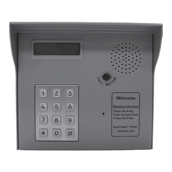
MOUNTING OPTIONS The VP keypad controls entry to or exit from a secured area. It works in conjunction with a controller and control software. The VP can be used to control gate access, building access, room access, elevator access, etc. -
Page 7: Ada Guidelines For Access Control
ADA Guidelines for Access Control The Americans with Disabilities Act of 1990 (ADA) prohibits discrimination in and ensures equal access to employment, government services, public accommodations, transportation, and commercial facilities for persons with disabilities. Some of the guidelines and requirements from this law can be applied to access control. - Page 8 ADA Mounting Requirements Keypads should be mounted so that the top of the number touchpad is no more than 48 inches above the finished floor with no obstructions in locations where wheelchair access is available only from the front. Keypads can be placed higher if a wall mount gooseneck allows closer access to the keypad.
- Page 9 All information contained herein is from the ADA web site and the Department of Justice Code of Federal Regulations Excerpt CFR Part 36 ADA Standards for Accessible Design revised July 1, 1994. PTI Security Systems is not liable for the information contained in this document and we strongly recommend that installers, owners, and builders work with qualified experts in the local, state, and federal interpretations of ADA and other similar laws.
-
Page 10: Mounting Access Devices
Mounting Access Devices The proper mounting height for the VP varies with the application. There are several options for mounting access devices: surface mount and wall mount. These can be attached to a wall or installed at an entrance using a gooseneck or bollard. -
Page 11: Wall Mount Gooseneck
Figure 7 Wall Mount Gooseneck A wall mount gooseneck allows the keypad to be mounted on a wall. It may be used for door strikes or for gates in driveways that run next to a building wall. A gooseneck can also be used to assist with wheelchair access to a device. -
Page 12: Single Bollard
Single Bollard A bollard is used as an attractive and functional stand for keypads. It helps protect the keypad from being struck by vehicles. It can be used in driveways for vehicle access or near doors as a decorative keypad stand. It can be painted any color to compliment the site. -
Page 13: Installing Vp Series Keypads
Installing VP Series Keypads Power and data communication wiring is the most important wiring component for VP devices. The VP requires power and communication lines to be supplied from the controller. We recommend that power and data communication be run through a single 18 AWG, 4-conductor shielded cable as this cable works well in most cases. - Page 14 Following are instructions on installing a VP series keypad and connecting the wiring run from the system controller: Open the device by removing the four stainless steel button head machine screws on the front of the keypad case using the security hex key provided with the unit.
- Page 15 8-32 x 3/8" Screws (qty 3) Cover hole with silicone Chassis Ground (connected to keypad) RG 59U Camera Cable (If optional camera is part of this device) Chassis Ground (connect to Earth Ground with wire nut and tape) 18GA, 2-Conductor Unshielded Cable (only if relay in this device used to trigger Gate/Door Strike) 18GA, 2-Conductor Shielded Cable...
- Page 16 Terminal Block P1 (Left) 1. Red DC+ * 2. * 3. Black DC- 5. Earth Ground if applicable * If using AC power, place the AC wires in slots 1 and 2. We recommend 12-18 VDC, but 12-18 VAC can be used. Figure 13 Terminal block P2, Pins 4, 5, and 6 are used for the relay.
- Page 17 10. Connect any additional features, such as intercom, camera, or gate operator that are installed on the VP. • Intercom. Connect the wires to terminal block P3 in the upper left corner of the board as shown in Figure 15. The connection and jumper settings will vary depending on whether the intercom is LEF Single Master Station, LEF Multiple Master Station, or NEM type intercom.
- Page 18 SEE INTERCOM JUMPER CONFIGURATION TABLE FOR PROPER JUMPER PLACEMENT INTERCOM JUMPER CONFIGURATION TABLE INTERCOM TYPE APEX JUMPER CONFIGURATION LEF Single NEM (ALL) Master All Others LEF (ALL BUT LEF Single SINGLE MASTER Master STATION) All Others LEF Single LEF (SINGLE Master MASTER STATION) All Others...
- Page 19 • Gate Operators. Most electric gate operators require a normally open contact (pins 4 & 5). Some electric door strikes require a normally closed contact (pins 5 & 6). If door strikes are used it is recommended that they be 12V DC. A shunting diode must then be installed across the solenoid to prevent ground spikes from disrupting the keypad communication.
-
Page 20: Testing The Keypad
Testing the Keypad Test the display by applying power to the keypad. The default date and time should appear on the display after power is applied. The controller updates the date and time to the remote keypad once a minute. The date and time on the display should update if the remote is configured correctly. -
Page 21: Operation
opeRation VP Keypad Setup Function To enter setup mode: Press the *, 0, and # keys simultaneously Enter the factory password: 8898 Press the # key NOTE: In the event the password is changed and then forgotten, you can disconnect power from the keypad and then hold the program button while reconnecting power. - Page 22 At this point, the basic parameters required for operation have been entered. If no other options are active or required, you can exit the setup mode. Following are optional parameters to customize the feel of the site. Setup Password Allows you to change the setup password from the factory default of 8898.
- Page 23 Time Format Controls how the time is displayed. Options are 12 Hour and 24 Hour. The 12 Hour displays the time as 12 Hour HH:MM:SS followed by am or pm. The hour will be displayed as 12:00:00 am to 12:00:00 pm. The 24 Hour format displays the time as HH:MM:SS without the am or pm indicator.
-
Page 24: Standard Display Messages
Standard Display Messages The standard display message for the VP keypad when no keys have been pressed is the date and time as shown. Fri, 08 / 01 / 08 12 : 13 Access Codes and Cards Depending on how the system is configured, the user will have an access code that can be entered or a magnetic stripe card that can be swiped. -
Page 25: Security Checks
Once the card is read, the keypad will go through the security checks described in the Security Checks section. If all of the security checks pass, the keypad will send the card data to the controller and wait for a response. - Page 26 Presence Required Check. After checking the tamper, the VP will check to see if the Presence in Req option has been selected. If it has been selected, the VP will check the input to see if a presence has been detected. If this option has been turned off or if a presence has been detected, the keypad will continue with the next security check.
-
Page 27: Access Response Messages
Access Response Messages There are several standard messages built in to the VP. The types of messages the VP receives in response to an access request vary depending on the conditions. The following briefly describes the conditions and the displayed message. For a valid Entry: * Welcome * Entry Is Granted... -
Page 28: System Maintenance
Once the card has been used, it should be disposed of. Additional cards can be ordered from PTI Security Systems. It is advisable to keep a supply of cards on hand. -
Page 29: Troubleshooting
tRoubleshooting For a New Installation, the typical problems encountered are related to the installation or configuration process. Start at step 1 in the Troubleshooting Steps section and proceed until the problem is found and resolved. For an Existing (previously working) Installation, the first step is to determine whether anything has been changed at the site. - Page 30 Step 3 Is the voltage at the VP, connector P1 pins 1 & 3, greater than 18 Volts? (Use a volt meter to measure the voltage). Yes – Voltage is too high, check power supply and retest No – Proceed to step 4 NOTE: Create a voltage map of the site by sketching out the locations of every AI device on the site.
-
Page 31: Test Card And Code Input
Step 6 Are any other devices set to the same address as the VP? Yes – Change one of the devices and retest No – Proceed to the step 7 This can be determined by checking the addresses on all of the devices or by disconnecting the VP and running the system setup report on the controller. -
Page 32: Test Individual Devices
If there are multiple problems or ongoing issues, the process in the previous step can be performed for an entire site. Generally, multiple problems are a sign of problems in the wiring, either from bad splices, pinched or nicked wires, radio frequency interference, water in the conduit, or incorrect wire type. -
Page 33: Test Multiple Devices Or Entire Site
Test multiple devices or entire site Generally, multiple problems are a sign of problems in the wiring, either from bad splices, pinched or nicked wires, radio frequency interference, water in the conduit, or incorrect wire type. To check the entire site for problems, use the following procedure: Allow for access and egress of customers and open all device housings. - Page 34 SEE INTERCOM JUMPER CONFIGURATION TABLE FOR LEF (EXCEPT SINGLE MASTER PROPER JUMPER PLACEMENT STATION) AND ALL NEM INTERCOM TYPES WIRING OFFICE - OR - TO SPEAKER AND CALL BUTTON (ONLY OFFICE KEYPAD W/ MAG READER & KEYPAD LEF SINGLE MASTER W/ INTERCOM) STATION WIRING TO WIEGAND READER...
-
Page 35: Warranty & Disclaimer
This warranty is exclusive and in lieu of all other warranties, expressed or implied, including but not limited to the implied warranties of merchantability and fitness for a particular purpose. PTI Security Systems will not be liable to anyone for any consequential or incidental damages for breech of this warranty or any other warranties. - Page 36 PTI Security Systems Products failed to function. However, if PTI Security Systems is held liable, directly or indirectly, for any loss or damage arising under this limited warranty or otherwise, PTI Security Systems’s maximum liability will not in any case...
- Page 40 For Technical Support, Please Visit: support.ptisecurity.com www.ptisecurity.com...
Need help?
Do you have a question about the VP keypad controls entry and is the answer not in the manual?
Questions and answers