Table of Contents
Advertisement
DK
+45 4567 0300
DE
+49 (0) 40 87 409 -560 Vertrieb / -484Technik
CH
+41 (0) 62 289 22 22
UK
+44 (0) 1536 614 070
Other markets +45 4567 0300
WSC 304 6102 install 1806-UK
WindowMaster International A/S, Skelstedet 13, DK-2950 Vedbæk
WSC 304 6102
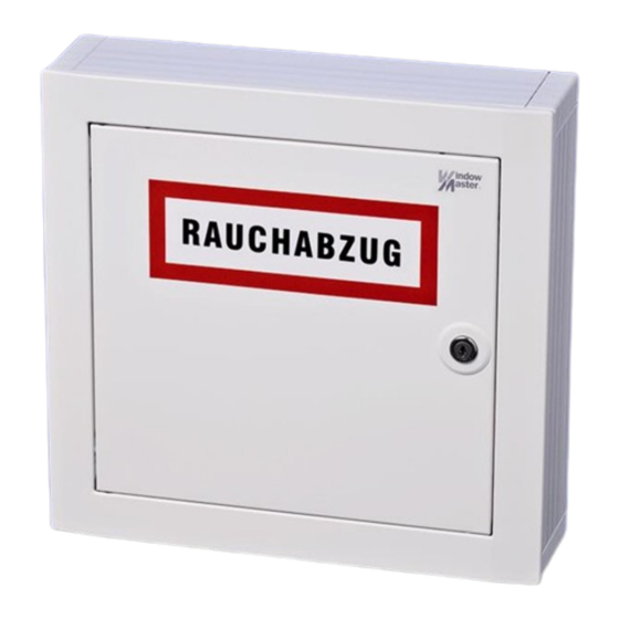
Smoke control unit
Operating manual / Technical information
Table of contents:
Commissioning
info.dk@windowmaster.com
info.de@windowmaster.com
info.ch@windowmaster.com
info.uk@windowmaster.com
info.dk@windowmaster.com
©WindowMaster 2009, 2018
www.windowmaster.com
®WindowMaster is a registered trademark used under licence by WindowMaster International A/S
Advertisement
Table of Contents

Summary of Contents for Window Master WSC 304 6102
-
Page 1: Table Of Contents
+44 (0) 1536 614 070 info.uk@windowmaster.com www.windowmaster.com Other markets +45 4567 0300 info.dk@windowmaster.com WSC 304 6102 install 1806-UK ©WindowMaster 2009, 2018 ®WindowMaster is a registered trademark used under licence by WindowMaster International A/S WindowMaster International A/S, Skelstedet 13, DK-2950 Vedbæk... -
Page 2: Safety Information
Safety information __________________________________________________________________________ Attention! Adherence to the following information is mandatory: Only allow correspondingly trained, qualified Field of application and skilled personnel to carry out installation work. The central control system is exclusively designed for the automatic closing of smoke extraction Reliable operation and the avoidance of systems, windows, flaps or doors. -
Page 3: Operating Elements And Fuse Review
Operating elements and fuse review ____________________________________________________________________________... -
Page 4: Technical Data
Technical data ____________________________________________________________________________ Smoke and heat extraction system alarm trip: The acoustic signal will only sounds in the break glass unit if the door is closed or if the door contact switch is pressed. Break glass unit: Break the glass in the break glass unit! Press the red button min. 0,5 sec.. The smoke extraction opens. An acoustic alarm signal sounds (continuous sound) in the break glass unit. - Page 5 Technical data ____________________________________________________________________________ Cascading smoke control units: The smoke control units can be cascaded by a monitored 2 wire connection from the alarm module of the master smoke control unit to the smoke detector input of the slave central panel. A malfunction in the cascaded smoke control units is detected via the 2 wire BUS cable.
- Page 6 Technical data ____________________________________________________________________________ Connection possibilities: 1) Actuators with a total power consumption of max. 4A 2) Smoke detectors, up to 10 pieces in 1 sensor group Optical smoke detector and/or thermo-differential sensor and/or heat max. sensor WSA 300, WSA 310 3) Break glass units (main), up to 4 per sensor group WSK 320 000X 4) Break glass units (secondary), up to 15...
- Page 7 Technical data ____________________________________________________________________________ Operation / LED diagnose Alarm (red) Lits when trigged Wind / rain (green) Lits when trigged Battery charge Charging voltage: 26,5V to 29V. depending on the surrounding temperature. Charging current: 350mA, current restricted. Short-circuit monitoring of the connection cables. Charging voltage disconnected in the event of a short-circuit.
- Page 8 Technical data ____________________________________________________________________________ Supply voltage 230V AC / 50Hz (+10% / -15%) Safety transformer According EN 61558 Mains amperage Max. 100VA Motor output voltage Load at actuator output Main 207V 25V DC 18V DC supply 230V 28V DC 21V DC voltage 253V 31V DC...
-
Page 9: Installation
Installation ____________________________________________________________________________ Cable routing Observe the safety information on page 2. For cable routing we recommend the use of fire protected cables retaining their function E90 or E30. However, this has to be agreed with the Engineer or, if necessary, with the local fire protection department. Do not reduce the cable cross sections specified in the cable lengths table. -
Page 10: Cable Lengths Table
Cable lengths table ____________________________________________________________________________ Maintaining the cable functions According to valid national regulations. The cable network for smoke ventilation systems („Cable system“) ends at the interface (junction box) for the actuator! The flexible, heat resistant connection cable of the smoke ventilation system actuator is part of the system component ‚electric motor actuation' and does not belong to the electrical installation! We recommend in all cases to discuss the type of cable routing with the competent fire fighting authorities. -
Page 11: Cable Plan
Cable plan ____________________________________________________________________________... -
Page 12: Standard Wiring Diagram
Standard wiring diagram __________________________________________________________________________... -
Page 13: Various Wiring Diagrams
Various wiring diagrams ____________________________________________________________________________... - Page 14 Commisioning ____________________________________________________________________________ When error message occur, please refer to chapter Operating elements and fuse review. An acoustic message only occurs in the Break glass unit with the door closed or the door contact switch pressed! The control centre is completely installed, without the operating voltage applied a) Check all mechanical and electrical components for damage.
- Page 15 Commisioning ____________________________________________________________________________ Automatic detectors a) Spray test aerosol on the detectors. b) The actuators move open through to the end position. The red LED in the detector, the red alarm LED (also in the control unit) and the permanent acoustic signal in the operating panel are ON. c) While running, press the Closed button at the ventilation button, then press both buttons, the actuators must neither close nor stop! d) Press the reset/Closed button in the operating panel.
-
Page 16: Maintenance
Maintenance ____________________________________________________________________________ The units of the smoke detection and heat extraction system have to be checked, serviced and, if necessary, repaired at least once per year by the manufacturer or an authorised specialist company. We also recommend the above to be carried out for pure ventilation units. Remove all soiling from the units of the smoke ventilation system.


Need help?
Do you have a question about the WSC 304 6102 and is the answer not in the manual?
Questions and answers