Table of Contents
Advertisement
Quick Links
Download this manual
See also:
User Manual
Advertisement
Table of Contents

Subscribe to Our Youtube Channel
Related Manuals for Vantron VT-M2M-TC VM


Summary of Contents for Vantron VT-M2M-TC VM
- Page 1 VT-M2M-TC VM VT‐M2M‐TC VM User’s Manual Chengdu Vantron Technology, Ltd. www.vantrontech.com.cn All Rights Reserved...
- Page 2 VT-M2M-TC VM Revision History: No. Version Description Date 1 V1.0 First release Aug.30, 2013 Change SmartDisplay Audio to mono 2 V2.1 Oct.10, 2013 line‐out( left channel) 3 V2.2 Add FCC warning statement Dec. 11, 2013 Change power in to 4 V2.3 Dec. 16, 2013 DC6‐36V( default 12V) 5 V2.4 Update product picture Jan. 2, 2014 6 V2.5 ...
-
Page 3: Table Of Contents
VT-M2M-TC VM Table of Contents Part I:Hardware Platform...................... 5 1 Foreword .......................... 6 1.1 Copyright Notice ........................6 1.2 Notes ............................6 1.3 Statement ..........................6 1.4 Disclaimer ..........................6 1.5 Limitation of Liability/Non‐warranty ..................7 1.6 Safety Instructions .........................7 1.7 Precautions ..........................7 ... - Page 4 VT-M2M-TC VM 2.8 Watchdog ........................ 32 2.9 Pnl7 Control ...................... 33 2.10 MCU Power Control .................... 33 2.11 Touch Screen ...................... 34 2.12 Host AP ........................ 35 2.13 OnBorad ......................... 38 3 Network Module ........................ 39 3.1 WIFI Control ...................... 39 ...
-
Page 5: Part I:hardware Platform
VT-M2M-TC VM Part I:Hardware Platform All Rights Reserved... -
Page 6: Foreword
Please contact our technical department for relevant operation solutions if there is any problem that cannot be solved according to this manual. Vantron reserves all rights of this manual, including the right to change the content, form, product features, and specifications contained herein at any time without prior notice. The latest version of this manual is at ... -
Page 7: Limitation Of Liability/Non-Warranty
VT-M2M-TC VM 1.5 Limitation of Liability/Non‐warranty For direct or indirect damage to this device or other devices of Vantron caused by failure of conforming to this manual or the safety instructions on device label, Vantron assumes neither warranty nor legal liability even if the device is still under warranty. The VT‐M2M‐TC VM should be installed, debugged and maintained by professional people. The outside antennas are not permitted to be installed or to be changed by ... - Page 8 VT-M2M-TC VM during transportation or placed under high temperature. Place cables properly: Do not place cables at any place with extrusion danger. Cleaning Instructions Please power off before cleaning the device. Do not use spray detergent. Clean with a damp cloth. Do not try cleaning exposed electronic components unless with a dust collector. Support for special fault: Power off and contact technical support personnel of Vantron in case of the following faults: The device is damaged. The temperature is excessively high. Fault is still not solved after the operation according to the manual. ...
-
Page 9: Overview
VT-M2M-TC VM 2 Overview 2.1 Introduction Thank you for choosing Vantron. It is our commitment to provide our valued customers with the embedded devices equipped with the state‐of‐the‐art technology and the best product services. Vantron’s M2M products are based on the most advanced ARM and Intel Atom processors and have low‐power consumption and high integration. The products ... -
Page 10: Product Series
VT-M2M-TC VM 2.2 Product Series Order Code VT-M2M-TC VM-4-1GM-8GF-GW2P-V Version: I: Extended Temperature Blank:Commercial temperature Wireless Module Option: 2G: 2G, 3G: 3G, ... -
Page 11: M2M-Tc Vm Hardware Instructions
VT-M2M-TC VM 3 M2M‐TC VM Hardware Instructions 3.1 Product Appearance Front Side View Back Side View Bottom View for optional embedded modules All Rights Reserved... -
Page 12: Specifications
VT-M2M-TC VM 3.2 Specifications Specifications Processor Intel® ATOM™, E620(T)0.6GHz E640(T)1GHz, E660(T)1.3GHz, E680(T),1.6GHz 32KB Instruction cache +23KB L1 cache, 512KB L2 cache Memory On Board RAM DDR2 512MB ( up to 2GB)@800MHz ROM Internal Half SATA SSD Module Internal (8GB or others) - Page 13 VT-M2M-TC VM Storage: -20°C ~ +70°C, ( ETR:-40°C ~ +85°C Optional) Humidity 5-95%RH at 25-35 (Non-Condensation) Cooling Mode Fan less, Heat Sink Approvals UL, FCC Class B, and CE All Rights Reserved...
-
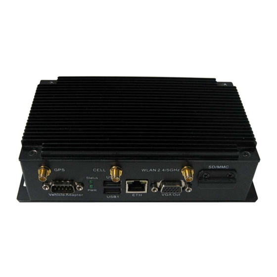
Page 14: Interface Instructions
VT-M2M-TC VM 3.3 Interface Instructions Front Side View Back Side View All Rights Reserved... -
Page 15: Dimension
VT-M2M-TC VM 3.4 Dimension All Rights Reserved... -
Page 16: Interface Description
VT-M2M-TC VM 3.5 Interface Description 3.5.1 Wide‐Range Power Interface Power connector outlook Description Pin Chassis Ground 1 Ground 2 Ground 3 N/C(Not Connect) 4 N/C(Not Connect) 5 N/C(Not Connect) 6 Power Input (6 ~ 36 VDC) 7 Power Input (6 ~ 36 VDC) 8 Acc Ignition Input 9 Ground 10 N/C(Not Connect) 11 ... - Page 17 VT-M2M-TC VM Power connector photo Pin Definition of Power Cord Color Pin Definition Red 7,8 + Black 2,3 ‐ Chassis Blue 1 Ground White 9 Ignition ...
-
Page 18: Smart Display Connector
VT-M2M-TC VM 3.5.2 Smart Display Connector Smart Display Connector Photo Pin Definition of Smart Display Connector Description Description LCD_BL_EN( Backlight Enable output) USB_D-(USB Data Negative Output Pin) Panel_PWR_EN(Panel Power Enable USB_D+(USB Data Positive Output Pin) output) LVDS Ground(ground pin) USB Ground(ground pin) - Page 19 VT-M2M-TC VM Optional Smart Display Cable. All Rights Reserved...
-
Page 20: Ethernet Interface
VT-M2M-TC VM 3.5.3 Ethernet Interface Standard RJ45 interface, supporting 10M/100M/1000M self‐adaptation, this is a standard RJ45 Ethernet port Pin Description Remarks IO 1 L_MDI_0P IO 2 L_MDI_0N IO 3 L_MDI_1P IO 4 L_MDI_1N 7 L_MDI_2P IO 8 L_MDI_2N IO 9 L_MDI_3P IO 10 L_MDI_3N IO All Rights Reserved... -
Page 21: D Sub-9 Rs232 Connector
VT-M2M-TC VM 3.5.4 D Sub‐9 RS232 Connector Standard vertical DB‐9 male connector ,The bit rate 460K Pin Description Remarks 1 DCD1/422TX+/485_A BIOS set BIOS set 2 RXD1/422TX‐/485_B BIOS set 3 TXD1/422RX+ 4 DTR1/422RX‐ BIOS set 5 DGND (ground pin) 6 DSR1 7 RTS1 8 CTS1 ... -
Page 22: Rs232/485,Can,External Io Connector
VT-M2M-TC VM 3.5.5 RS232/485,CAN,External IO Connector 12pins 3.81 pitch terminal with screw lock Load capacity: more than 128 nodes/RS485 channel bit rate:115200 ‐‐ CAN: The bit rate can be programmed to a maximum of 1Mbit/s Pin Description Remarks 1 TXD2/485_2_A ... -
Page 23: Vga Interface
VT-M2M-TC VM 3.5.6 VGA Interface Standard vertical DB‐15 Female VGA connector bit rate:460K Pin Description 1 RED 2 GREEN 3 BLUE 4 N.C. 5 GND 6 GND 7 GND 8 GND 9 +5VDC 10 GND 11 N.C. 12 SD_DDC 13 HSYNC 14 VHYNC ... -
Page 24: Usb Host Connector
VT-M2M-TC VM 3.5.7 USB Host Connector Dual vertical USB A type interface, USB2.0 Description Pin USB1_VCC(+5VDC) A1 USB1_D‐ A2 USB1_D+ A3 A4 USB1_DGND(ground pin) USB2_VCC(+5VDC) B1 USB2_D‐ B2 USB2_D+ B3 USB2_DGND(ground pin) B4 3.5.8 LED PWR LED: light system power OK(main power up);off system power turn off Status LED:Blink SATA HDD active. -
Page 25: Operation Notice
VT-M2M-TC VM 3.6 Operation Notice 3.6.1 Change SIM Card Push the small button on the left of SIM Card Holder, and install the SIM card to the holder. Then push the holder into the Slot. All Rights Reserved... -
Page 26: Tips
Caution signs in this manual remind of possible danger. Please comply with relevant safety tips below each sign. Meanwhile, you should strictly conform to all safety tips for operation environment. Notice Considering that reasonable efforts have been made to assure accuracy of this manual, Vantron assumes no responsibility of possible missing contents and information, errors in contents, citations, examples, and source programs. Vantron reserves the right to make necessary changes to this manual without prior notice. No part of this manual may be reprinted or publicly released in for All Rights Reserved... - Page 27 (In the aim of avoiding accidents as far as possible, it is not allowed to replace the system or change components unless with permission and certification. Please contact the technical department of Vantron or local branches for help. ) ...
-
Page 28: Part Ii:software Reference
1 Introduction Thank you for choosing Vantron. It is our commitment to provide our valued customers with the embedded devices equipped with the state of the art technology and the best product services. Vantron’s M2M products are based on the most advanced ARM and Intel Atom processors and have low power consumption and high integration. -
Page 29: Functionalities Layout
VT-M2M-TC VM mcupower Power control configure mcupowerui Power control configure UI adxl Digital Accelerometer pnl Pnl7 control hostapdup Host AP up hostapdoff Host AP off 1.4 Functionalities layout The below table lists VT‐M2M‐TC VM features. Chips or Interfaces Details UART VT‐M2M‐TC has 4 UART ports: ... -
Page 30: 2 Base Control
VT-M2M-TC VM 2 Base Control Open the terminal (CTRL+ALT+T), then get into the demo directory. The directory patch is /programs/demo. ex: $cd /programs/demo 2.1 Power Control power can|gps|3g] [on|off] can: Power control of CAN Module gps: Power control of GPS Module ... -
Page 31: Serial Com Control
VT-M2M-TC VM clear: Clear GPIO to low level, need set the GPIO as output first. gpionum: The GPIO be operated. 0 to 5 is EXTIO, 10 is back light power ex1: Set EXTIO2 to high. $sudo ./gpioctl dirout 2 $sudo ./gpioctl set 2 ex2: Read level of EXTIO2. $sudo ./gpioctl dirin 2 $sudo./gpioctl get 2 ex3: Set EXTIO2 to low. $sudo ./gpioctl dirout 2 $sudo ./gpioctl clear 2 2.4 Serial COM Control a. RS232 DB9 COM : Open the Cutecom, this software get from “Ubuntu Software Center”. $sudo cutecom Select Device, Baudrate, Data bits, Stop bits, Parity , Handshake, then press “Open device” ... -
Page 32: Audio And Video Control
VT-M2M-TC VM 2.5 Audio And Video Control a. Audio arecord: $sudo arecord –t wav test.wav b. Audio aplay: $sudo aplay test.wav c. Video player, the test video in “/programs/tmp “: $sudo mplayer /programs/tmp/1.mp4 2.6 SD card Control a. Insert SD card ,then look over device: $sudo fdisk –l b. mount SD card device: $sudo mount /dev/mmcblk0 /mnt 2.7 ADXL345 Control Get Digital Accelerometer: $sudo ./adxl X: 233 Y: 2 ... -
Page 33: Pnl7 Control
VT-M2M-TC VM c. Start watchdog or reboot system: $sudo watchdog 2.9 Pnl7 Control The communication protocol in the PNL CD/DVD 740P56‐5KxxxxxxVT_PNL7_xxx/SW/CommunicationProtocol MCU with PC V1.x.pdf. Control pnl7 and get button event from pnl7. $sudo ./pnl 1.Get pnl version 2. Get pnl back light value ………… ………… 25. Exit Input Select: 2.10 MCU Power Control The communication protocol in this CD/DVD SW/doc/vm‐smbus‐protocol_xx.pdf. a. Get the MCU power value (D‐Dec H‐Hex): $sudo ./mcupower get 1 MCU on delay:(Dec)5 (Hex)5 b. Set the MCU power value , set value is Dec: $sudo ./mcupower set 1 200 MCU on delay OK c. Set and get MCU power value form UI: $sudo ./mcupowerui ... -
Page 34: Touch Screen
VT-M2M-TC VM Use power supply equal or more than 12V output. "Read" all values Change this value to 10.8V, to settle long cable with voltage drop issue. "Write" settings to save the ACC ... -
Page 35: Host Ap
VT-M2M-TC VM b. Then calibrate and set touch screen: 2.12 Host AP First of all, disconnect all network. a. Open the WIFIAP software: All Rights Reserved... - Page 36 VT-M2M-TC VM b. Input the pass word and you will into the following interface: c. Open Options‐>Settings, set the host AP and DNSMASQ: Note: When you changed the setting, you need click “Save”. Ethernet (eth0) or cell (ppp0), then d. Connect activate the host AP: e. The active host AP: All Rights Reserved...
- Page 37 VT-M2M-TC VM When activate the host AP, you can scan and connect the hot port, and access to the other network which you configure. Close the activation state: All Rights Reserved...
-
Page 38: Onborad
VT-M2M-TC VM 2.13 OnBorad a. Open onboard b. Preferences or Quit All Rights Reserved... -
Page 39: 3 Network Module
VT-M2M-TC VM 3 Network Module The network be managed by the network connections, can use network connections tool from system tools. 3.1 WIFI Control a. Connect the WIFI hotspot: All Rights Reserved... -
Page 40: Control
VT-M2M-TC VM 3.2 3G Control Note: When you disconnected the 3G or connected error, you must restart the device: $sudo power 3g off $sudo power 3g on a. Open network connections. b. Select mobile Broadband and press “add” button to add device: All Rights Reserved... - Page 41 VT-M2M-TC VM c. Select the telit wireless device. d. Select country, we are in China, so we select China. e. Select provider from list: All Rights Reserved...
- Page 42 VT-M2M-TC VM f. Apply the config: g. Set phone number , user and password: h. Connect the internet: All Rights Reserved...
-
Page 43: Bluetooth Control
VT-M2M-TC VM 3.3 Bluetooth Control Bluetooth is a wireless protocol that allows you to connect many different types of devices to your computer. Bluetooth is commonly used for headsets and input devices like mice and keyboards. You can also use Bluetooth to send files between devices, such as from your computer to your cell phone. Turn Bluetooth on or off ... - Page 44 VT-M2M-TC VM c. Then locate that small Bluetooth icon on the top panel and click on it. Then from the menu that you get, click on that which says ‘Bluetooth Settings…’ . d. This should open the default configuration window and you’ll see a button that lets you turn on/off Bluetooth as shown below. Now simply click and drag it to the right‐side until it says ‘ON’ to turn it on. Then click on the ‘+’ sign at the bottom of the ‘Bluetooth Settings’ window to add the device ...
- Page 45 VT-M2M-TC VM f. Now when you’re ready, click on the device that you want a connection to be established and click ‘Continue’. g. This PIN number is only displayed for a few seconds so you should better hurry up . If it’s a phone, then your phone will ask for this PIN code automatically. h. If you successfully entered the PIN number then you should see a message saying ...
- Page 46 VT-M2M-TC VM 3.3.2 Send File You can use the Bluetooth device, if you’ve connected a mobile phone then you can use ‘Bluetooth Settings’ window. Click on the Bluetooth icon on the top panel for sending or browsing files etc as shown below. All Rights Reserved...
- Page 47 VT-M2M-TC VM 3.3.3 Accept File a. First of all, make sure the Bluetooth devices are ‘visible’, pair the Bluetooth devices. b. Open file sharing. c. Configure Bluetooth. d. Send file from others Bluetooth device, the file will be saved in /home/vantron/Download. All Rights Reserved...
-
Page 48: 4 Gps Module
VT-M2M-TC VM 4 GPS Module 4.1 Get GPS Data Open /dev/ttyS2 , read GPS data $sudo ./gps 38400 /dev/ttyS2 4.2 GPS Data Format 4.2.1 GPGGA Global Positioning System Fix Data Name Example Data Description Sentence Identifier $GPGGA Global Positioning System Fix Data Time 170834 17:08:34 Z Latitude 4124.8963, N 41d 24.8963' N or 41d 24' 54" N Longitude 08151.6838, 81d 51.6838' W or 81d 51' 41" W W Fix Quality: 1 Data is from a GPS fix ‐ 0 = Invalid ... - Page 49 VT-M2M-TC VM a = N or S yyyyy.yy = Longitude of position a = E or W x = GPS Quality indicator (0=no fix, 1=GPS fix, 2=Dif. GPS fix) xx = number of satellites in use x.x = horizontal dilution of precision x.x = Antenna altitude above mean‐sea‐level M = units of antenna altitude, meters x.x = Geoidal separation M = units of geoidal separation, meters x.x = Age of Differential GPS data (seconds) xxxx = Differential reference station ID 4.2.2 GPGSA GPS DOP and active satellites ex1: $GPGSA,A,3,,,,,,16,18,,22,24,,,3.6,2.1,2.2*3C ex2: $GPGSA,A,3,19,28,14,18,27,22,31,39,,,,,1.7,1.0,1.3*35 ex3: $GPGSA,<1>,<2>,<3>,<4>,,,,,<11>,<12>,<13>,<14>,<15>,<16>,<17> *<18> 1 = Mode: M=Manual, forced to operate in 2D or 3D A=Automatic, 3D/2D ...
- Page 50 VT-M2M-TC VM 2 = Message number 3 = Total number of SVs in view 4 = SV PRN number 5 = Elevation in degrees, 90 maximum 6 = Azimuth, degrees from true north, 000 to 359 7 = SNR, 00‐99 dB (null when not tracking) 8‐11 = Information about second SV, same as field 4‐7 12‐15= Information about third SV, same as field 4‐7 16‐19= Information about fourth SV, same as field 4‐7 4.2.4 GPRMC Recommended minimum specific GPS/Transit data ex1: $GPRMC,081836,A,3751.65,S,14507.36,E,000.0,360.0,130998,011.3,E*62 ...
- Page 51 VT-M2M-TC VM 1 = UTC of position fix 2 = Data status (V=navigation receiver warning) 3 = Latitude of fix 4 = N or S 5 = Longitude of fix 6 = E or W 7 = Speed over ground in knots 8 = Track made good in degrees True ...
-
Page 52: 5 Update System
VT-M2M-TC VM 5 Update System 5.1 Make USB boot Stick and Copy Image to USB stick Create PC condition: Create a bootable USB stick on Windows XP/ Win7, the first thing you need to do is insert a USB stick with at least 2GB of free space into your PC. Here use an USB installer tool to write the image ISO to USB stick. Please copy the file SW/tools/Universal‐USB‐Installer‐1.9.3.5.exe to your PC anywhere. USB stick making steps in detail as follows: a. Copy SW/image/xxx.iso image into your PC. b. Select the “Try Unlisted Linux ISO” from the dropdown list. Click 'Browse' and select the image ISO file. All Rights Reserved... - Page 53 VT-M2M-TC VM Choose the USB drive and click 'Create'. All Rights Reserved...
-
Page 54: Update Steps
VT-M2M-TC VM 5.2 Update steps a. When the bootable USB stick create over, insert the USB stick into VT‐M2M‐TC. And connect a USB keyboard on the M2M‐TC. b. Power ON the VT‐M2M‐TC, and step into BIOS by press the “Delete” key on the keyboard. In the BIOS, set the first boot option for boot up by USB stick. The user guidance of the BIOS is in the package of HW/ 700N16‐6Bxxxxxx_VT‐M2M‐TC_VM_xxx.zip. c. Select the first option “clonezilla live with img 700Pxxxxxx”. All Rights Reserved... - Page 55 VT-M2M-TC VM d. When ask “Are you sure want to continue??” or “Let me ask you again, Are you sure you want to continue??” , please input ‘y’ all. e. The system is updating. When update over, the system will power off. Re‐power VT‐M2M‐TC, and step into the BIOS, and restore the first boot option to hard disk. All Rights Reserved...
- Page 56 US Office: Vantron Technology, Inc. Address: 1292 Kifer Road #807, Sunnyvale, CA 94086 Tel: 510-304-7666 Email: sales@vantrontech.com China Office: Chengdu Vantron Technology, Ltd. Address: 3rd floor, 3rd building, No.9, 3rd WuKe East Street, WuHou District, Chengdu, P.R. China 610045 Tel: 86-28-8512-3930/3931, 8515-7572/6320 Email: sales@vantrontech.com.cn...
Need help?
Do you have a question about the VT-M2M-TC VM and is the answer not in the manual?
Questions and answers