Table of Contents
Advertisement
Quick Links
Installation and Maintenance Manual
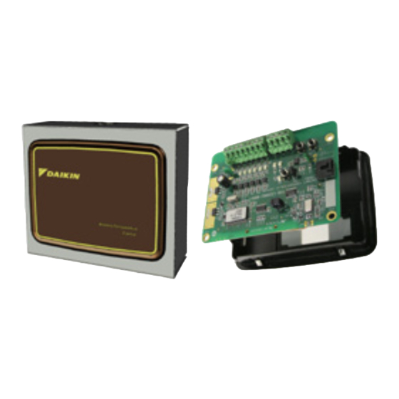
T9000 Wireless 24VAC Thermostat
Remote Control Node (RCN)
For use with any Daikin unit that is able to utilize a standard, single-stage
24VAC remote wall thermostat
•
T9000 Wireless RCN Assembly Kit Part No: 910108604
For use with Console Water Source Heat Pump Models WMHC & WMHW
•
Heat Pump Kit Part No. 668898501
For Water Source Heat Pumps - Vertical Stack Models WVHC & WVHF
•
Heat Pump Kit Part No. 910139783
IM 1119-1
Group: WSHP
Part Number: 910154889
Date: June 2014
T9000 Wireless RCN Assembly Kit No. 910108604
Console Model Heat Pump Kit Part No. 668898511
Advertisement
Table of Contents

Related Manuals for Daikin T9000


Summary of Contents for Daikin T9000
- Page 1 Part Number: 910154889 Date: June 2014 T9000 Wireless 24VAC Thermostat Remote Control Node (RCN) For use with any Daikin unit that is able to utilize a standard, single-stage 24VAC remote wall thermostat • T9000 Wireless RCN Assembly Kit Part No: 910108604 T9000 Wireless RCN Assembly Kit No.
-
Page 2: Table Of Contents
Control Logic Tables . . . . . . . . . . . . . . . . . . . . . . . . . . . . . . 20 T9000 Wireless RCN Kit No. 910108604 – Parts Included ..4 Console Water Source Heat Pump Models WMHC &... -
Page 3: Safety Information
Wireless Programmable (#68898001) or Daikin T9000 Wireless which employs trained personnel. Non-Programmable (#68898101) thermostat, as noted. Note: No other thermostats will function with the T9000 RCN. CAUTION Installation and maintenance is to be performed only by qualified personnel who are familiar with, and in compliance with state, local and national codes and regulations, and experienced with this type of equipment. -
Page 4: Rcn Installation
RCN Installation 4 . Attach the RCN housing back-plate to a temperature sufficient location. T9000 Wireless RCN Kit No . 910108604 – Parts Included a . Attach RCN housing back-plate to a suitable location, 1 . Metal RCN Housing Box 4 . (8) Industrial Tape Strips preferably avoiding extreme temperature conditions and 2 . RCN 5 . - Page 5 6 . Wire all appropriate terminals on the removed Remote Control Figure 3: Adhesive tape used to secure the RCN box Node terminal block (RCN), using appropriate lengths of field- supplied low voltage wiring. Make sure to follow all national and local code requirements when routing low voltage control wires. 7 . Feed the stripped leads of the thermostat low-voltage wires through the bushing of the RCN housing, to connect to the unit control board or terminal strip/block. Figure 5: Feed stripped wire leads through bushing on the RCN housing NOTICE It is recommended that the terminal block on the RCN control module be removed when making terminal connections, to avoid excessive handling of the static sensitive RCN control module.
- Page 6 8 . Remove screws and/or panels that will allow access to Figure 7: Connect wire leads from RCN to the appropriate the inside of the unit control box, or locate the remote terminals on the unit control board thermostat terminal strip/block, to connect the RCN to the unit control board. 9 . Connect the stripped wire leads from the RCN assembly to the appropriate terminals on the unit control board or remote thermostat terminal strip/block.
- Page 7 T9000 Wireless Thermostat. Refer to "RCN Configuration Table for All WSHP Units" on page for instructions on how to program the RCN. 12 . After the RCN has been linked with a T9000 Wireless Thermostat, and any RCN application-configuration programming is completed; re-attach the RCN box top (with bezel, overlay, wire harness & control module) to the unit- mounted RCN back plate, with the 3 previously removed screws (2-top/1-bottom) from step 2.
-
Page 8: Console Water Source Heat Pump Models Wmhc
Console Water Source Heat Pump Models Figure 10: Remove four (4) screws WMHC & WMHW - RCN Installation Heat Pump Kit Part No . 668898501 – Parts Included 1 . RCN 2 . Wireless Overlay Introduction Although the wireless temperature control kit is factory supplied it may also be field installed, which requires units set up for unit-mounted 24V thermostat control. - Page 9 5 . Using a small regular screwdriver, loosen the set screws 6 . After making all wire connections, plug the RCN terminal holding the wires to the terminal plug on the touchpad plug onto the RCN board. board (Figure 12). 7 . Apply the provided wireless remote control decal over the NOTE: Remove one wire at a time and reconnect to the face of the touchpad control (Figure 13). corresponding terminal on the RCN terminal plug.
-
Page 10: Vertical Stack Water Source Heat Pump Models Wvhc
Vertical Stack Water Source Heat Pump 3 . Remove the filter and then the front panel/filter rack (Figure 14). Models WVHC & WVHF - RCN Installation Figure 14: Remove filter and front panel/filter rack Heat Pump Kit Part No . 910139783 – Parts Included Remove front panel screws 1 . RCN 3 . - Page 11 5 . Feed the provided RCN wire harness through the knockout Figure 16: RCN wire harness connections to the MicroTech opening and snap the RCN bezel and board assembly into III unit controller terminal plug the knockout (Figure 15). NOTE: Feed RCN wire harness into the control box through the top wire hole.
-
Page 12: Rcn Application - Configuration
RCN Application – Configuration Figure 17: RCN LED Indicator Lamp Locations Remote control nodes are factory-programmed to default settings. Settings can be changed for special applications by following the directions below. While programming, refer to Figure 17 and the "RCN Configuration Table for All WSHP Units" on page 13. 1 . To enter the setup mode press and hold PB3 until the LED indicator lamps flash alternately. 2 . D4 will flash once indicating, "Table 1 - Control Mode" on page Figure 17; followed by D3 flashing 1 time, indicating the configuration that is active (1 flash for... -
Page 13: Rcn Configuration Table For All Wshp Units
RCN Configuration Table for All WSHP Units = WSHP Configuration Function Selection Flash Flash Description Table 1 - Control Mode Count Count Fan will speed-hunt in AUTO. Fan speed 1, 2, or 3 may be manually selected to run continuously at that WSHP selected speed. Fan will speed-hunt in Auto. Fan speed 1, 2 or 3 may be manually selected to run continuously at that Heat Pump selected speed. Only control mode where O/B terminal will ever be energized Table 2 - Short Cycle The “Y” terminal/control line output signal is delayed by 3-minutes after a compressor run cycle or upon unit Short Cycle - Active power-up The “Y” terminal/control line output signal is allowed to energize immediately after a compressor run cycle or Short Cycle - Inactive upon unit power-up . Table 3 - Fan Speed Fan Speed 1 Only Fan will speed-hunt in AUTO. Fan speed 1 or 2 may be selected to run continuously. - Page 14 RCN Configuration Table (Continued) = WSHP Configuration Function Selection Flash Flash Description Table 3 - Fan Speed Count Count Off/Disabled System will not respond to unoccupied status conditions. Temp will drift 2 degrees (↓ in Heating, ↑ in Cooling), when unoccupied mode is in effect 2°F drift from set-point (Contacts Closed = Unoccupied). Temp will drift 4 degrees (↓ in Heating, ↑ in Cooling), when unoccupied mode is in effect 4°F drift from set-point (Contacts Closed = Unoccupied). Temp will drift 6 degrees (↓ in Heating, ↑ in Cooling), when unoccupied mode is in effect 6°F drift from set-point (Contacts Closed = Unoccupied).
- Page 15 RCN Configuration Table (Continued) = WSHP Configuration Function Selection Flash Flash Description Table 5 - Occupancy Timeout Count Count 2-Minute Delay System responds to an unoccupied status condition within 2-minutes. 1-Hour Delay System responds to an unoccupied status 1-hour after condition is sensed. 4-Hour Delay System responds to an unoccupied status 4-hours after condition is sensed.
-
Page 16: Installing And Removing Nodes
Installing and Removing Nodes Step 1 Press the SW4-INSTALL button inside the thermostat. The A T9000 wireless thermostat and remote control node will not display will change to the install session screen shown in operate as a system until they are linked together through the Figure 18, with the “install” icon blinking. installation process. The linking process binds one or more... - Page 17 Apply power to the RCN (apply power to the Step 3 unit) or press PB3 if power has been applied to the RCN before The node number digits will now flash. Use the UP button to the link request has been initiated from a T9000 wireless set the node number you wish to install 0-7. If this is the first thermostat. See Figure 20 on page node or only node to be installed to this thermostat, leave the node number at zero.
- Page 18 Figure 20: Wireless Control Node Figure 21: Install – Link Display Please Wait Good If another node is to be installed to this thermostat, press the HEAT/COOL button again. The “Install” icon will flash. As was done previously, press the HEAT/COOL button (Step Two). When the SW9-LINK button is pressed, the thermostat will The node number will begin blinking, select the node number display a “Please Wait” message, see Figure 21 in the bottom by one using the UP button and continue with the remaining right corner of the LCD while it searches for a node. You have steps. When all nodes are installed, press the SW4-INSTALL several seconds to initiate a Link Service Request at the button to close the installation session and return to normal remote control node. Often it is easiest to have the thermostat thermostat operation. in your hand while you are near the node. The thermostat will If for any reason there was a problem encountered during link with the first node it hears that indicates a Link Service the final installation and linking step, a “Bad” message will...
- Page 19 Installing Multiple Nodes to a Thermostat Wait” message, see Figure 21 on page 18 in the bottom right corner of the LCD while it searches for nodes. Once the Multiple nodes are typically installed to a thermostat by linking thermostat finds its installed node(s), linking information is each as a different number (0-7). If a node is not sending removed from the nodes and the thermostat, “please wait” a signal to the thermostat for any reason, such as loss of message will be extinguished, and a “Good” message will power, it will turn off the antenna symbol indicating a break appear as shown in Figure 21 on page in communication and attempt to find the missing node, increasing battery power drain. If, in your application, a node Thermostat Installation Reset...
-
Page 20: Control Logic Tables
Control Logic Tables Logic Table 1 Heat/Cool Mode (WSHP) Cooling Cooling Heating Heating Output Fan Auto Fan 1, 2 or 3 Fan Auto Fan 1, 2 or 3 ON ≥ 1° ON ≥ 1° ON ≥ 1° ON ≥ 1° Fan 1 OFF ≤ 0° OFF ≤ 0° O FF ≤ 0° OFF ≤ 0° ON ≥ 2° ON ≥ 1°... -
Page 21: Frequently Asked Questions
“What does the antenna symbol on the display thermostat will continually attempt to initiate communication mean?” with the de-activated unit node, causing excessive battery The T9000 thermostat displays the antenna symbol as drain. In a hotel meeting room with multiple packaged terminal indication that it is communicating with its remote control air conditioner units, seating may be arranged such that one node(s) (RCN). If communication is not established, the... - Page 22 A blank display indicates your batteries are depleted. When the “Can I use another T9000 thermostat without low battery icon comes on there is approximately one week of interference?” battery life remaining. We recommend that when you change Yes. A T9000 thermostat and its RCN will talk between...
-
Page 23: Descriptions
T9000 Programmable Wireless Thermostat Button Descriptions Figure 22: T9000 Overview www.DaikinApplied.com IM 1119-1... - Page 24 Daikin Applied Training and Development Now that you have made an investment in modern, efficient Daikin equipment, its care should be a high priority. For training information on all Daikin HVAC products, please visit us at www.DaikinApplied.com and click on Training, or call 540-248-9646 and ask for the Training Department. Warranty All Daikin equipment is sold pursuant to its standard terms and conditions of sale, including Limited Product Warranty. Consult your local Daikin Applied Representative for warranty details. To find your local Daikin Applied Representative, go to www.DaikinApplied.com. Aftermarket Services To find your local parts office, visit www.DaikinApplied.com or call 800-37PARTS (800-377-2787). To find your local service office, visit www.DaikinApplied.com or call 800-432-1342. This document contains the most current product information as of this printing. For the most up-to-date product information, please go to www.DaikinApplied.com. Products manufactured in an ISO Certified Facility. IM 1119-1 ©2014 Daikin Applied (6/14) | (800) 432–1342 | www.DaikinApplied.com...
Need help?
Do you have a question about the T9000 and is the answer not in the manual?
Questions and answers