
Related Manuals for Daikin BRC51D61


Summary of Contents for Daikin BRC51D61
- Page 1 OPERATING MANUAL Operating Manual English Handset Wired OM-BRC51D-0616(2)-DAIKIN Part No.: R08019045189B...
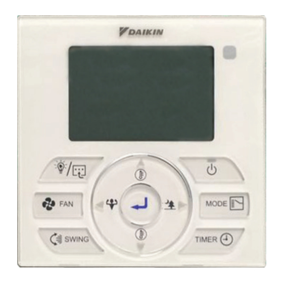
- Page 3 BRC51D Controller Indication BRC51D61/63 Controller Indication BRC51D62/66 Controller Indication IR receiver...
- Page 4 OPERATING INSTRUCTION Button – Press once to start the air conditioner unit. – Press again to stop the unit. Button – Press the button to increase or decrease the set temperature. – Pressing FAN and or VIEW button simultaneously to toggle the temperature SWING setting between °C and °F.
- Page 5 B) ON/OFF Timer Setting – Daily Timer Setting a. Continuously press for 3 seconds. b. ON Timer 1 Setting “MON” will blink. II. Use button to select the Day and press button to confirm the Day. III. Hour will blink. Use button to toggle between Hour and Minute.
- Page 6 e. OFF Timer 2 Setting Press again to enter OFF Timer 2 setting, then “MON” will blink. II. Use button to select the Day and press button to confirm the Day. III. Hour will blink. Press button to change the Hour. Press button to confirm the Hour, then Minute will blink.
- Page 7 Button – Press button to turn ON/OFF the light on ceiling cassette unit. – Continuously press for 3 seconds to enter Feature selection. SLEEP ( ) will blink, use button to scroll between SLEEP ( ), ECO+ ( ), POWERFUL ( ), QUIET ).
-
Page 8: Error Indicator
ERROR INDICATOR ! NOTE – The LED will blink if error occurred. If there is any abnormal condition detected, BRC51D controller will blink the error code. The format for the error code will be as following: DX Error Code ERROR MEANING CODE Room Sensor Open or Short... - Page 9 ERROR MEANING CODE Outdoor PCB Error High Pressure Protection Low Pressure Protection Compressor Motor Lock/Compressor Overloaded Compressor Start-Up Error Outdoor DC Fan Motor Lock AC Input Over Current EXV Error 4 Way Valve Error Discharge Pipe Overheat Heat Exchanger Overheat Compressor Sensor System Error High Pressure Switch Error Compressor Feedback Detection Error...
-
Page 10: Hardware Setting
HARDWARE SETTING ! NOTE – Hardware setting should be performed by installers or technicians. The wired handset has 3 jumpers option to control the board function. Table 2.0: Summary of Hardware Settings OPTION With Jumper Without Jumper SET TEMP. RANGE Set Temperature : 20°C - 30°C Set Temperature : 16°C - 30°C * TURBO_QUIET... - Page 11 2.2 Location where the wiring will enter the remote controller. Top center outlet Cut the plastic at the notched area and remove any remaining burrs. 2.3 Installation procedure for the lower case. When wiring the remote controller through the top center or rear access points, attachment of the wire to the lower case is required before it is wall mounted.
- Page 12 Umeda Center Bldg., 2-4-12, Nakazaki-Nishi, Kita-ku, Osaka, 530-8323 Japan Tokyo office: P.O.Box 18674, Jebel Ali Free Zone, Dubai-UAE JR Shinagawa East Bldg., 2-18-1, Konan, Email: info@daikinmea.com Minato-ku, Tokyo, 108-0075 Japan Web: www.daikinmea.com http://www.daikin.com/global/ Importer for Turkey: Allianz Plaza-Kucukbakkalkoy Mah.Kayısdagi Cad.No:1 34750 Atasehir-ISTANBUL / TURKIYE...
- Page 13 Umeda Center Bldg., 2-4-12, Nakazaki-Nishi, Kita-ku, Osaka, 530-8323 Japan P.O.Box 18674, Jebel Ali Free Zone, Dubai-UAE Tokyo office: Email: info@daikinmea.com JR Shinagawa East Bldg., 2-18-1, Konan, Web: www.daikinmea.com Minato-ku, Tokyo, 108-0075 Japan http://www.daikin.com/global/ :Importer for Turkey Allianz Plaza-Kucukbakkalkoy Mah.Kayısdagi Cad.No:1 34750 Atasehir-ISTANBUL / TURKIYE...
- Page 14 2.2 ﺍﻟﻤﻜﺎﻥ ﺍﻟﺬﻱ ﺳﺘﺪﺧﻞ ﻓﻴﻪ ﺃﺳﻼﻙ ﺟﻬﺎﺯ ﺍﻟﺘﺤﻜﻢ ﻋﻦ ﺑ ﹸﻌﺪ ﻣﺨﺮﺝ ﺍﻟﻤﺮﻛﺰ ﺍﻟﻌﻠﻮﻱ .ﺍﻗﻄﻊ ﺍﻟﺒﻼﺳﺘﻴﻚ ﻓﻲ ﺍﻟﻤﻨﻄﻘﺔ ﺍﻟﻤ ﹸ ﺤﺪﺩﺓ ﻭﺃﺫﻝ ﺃﻱ ﻧﺘﻮﺀﺍﺕ ﻣﺘﺒﻘﻴﺔ .ﺇﺟﺮﺍﺀ ﺗﺜﺒﻴﺖ ﺍﻟﻐﻄﺎﺀ ﺍﻟﺴﻔﻠﻲ ﻋﻨﺪ ﺗﻮﺻﻴﻞ ﻭﺣﺪﺓ ﺍﻟﺘﺤﻜﻢ ﻋﻦ ﺑ ﹸ ﻌﺪ ﻣﻦ ﺧﻼﻝ ﺍﻟﻤﺮﻛﺰ ﺍﻟﻌﻠﻮﻯ ﺃﻭ ﻧﻘﺎﻁ ﺍﻟﻮﺻﻮﻝ ﺍﻟﺨﻠﻔﻴﺔ، ﻳﺘﻄﻠﺐ ﺗﺜﺒﻴﺖ ﺍﻟﺴﻠﻚ ﺑﺎﻟﻐﻄﺎﺀ .ﺍﻟﺴﻔﻠﻲ...
- Page 15 ﺿﺒﻂ ﺍﻟﺠﻬﺎﺯ ! ﻣﻼﺣﻈﺔ .– ﻳﺠﺐ ﺇﺟﺮﺍﺀ ﺿﺒﻂ ﺍﻟﺠﻬﺎﺯ ﺑﻮﺍﺳﻄﺔ ﻋﻤﺎﻝ ﺍﻟﺘﺮﻛﻴﺐ ﺃﻭ ﺍﻟﻔﻨﻴﻴﻦ .ﻭﺻﻠﺎﺕ ﻋﺒﻮﺭ ﻟﻠﺘﺤﻜﻢ ﻓﻲ ﻭﻇﻴﻔﺔ ﺍﻟﻠﻮﺣﺔ ﺗﺘﻀﻤﻦ ﺍﻟﺴﻤﺎﻋﺔ ﺍﻟﺴﻠﻜﻴﺔ ﺧﻴﺎﺭ : ﻣﻠﺨﺺ ﺇﻋﺪﺍﺩﺍﺕ ﺍﻟﺠﻬﺎﺯ ﺍﻟﺠﺪﻭﻝ ﺑﺪﻭﻥ ﻭﺻﻠﺔ ﺍﻟﻌﺒﻮﺭ ﻣﻊ ﻭﺻﻠﺔ ﺍﻟﻌﺒﻮﺭ ﺍﻟﺨﻴﺎﺭ ﺿﺒﻂ ﻧﻄﺎﻕ ﺩﺭﺟﺔ ﺍﻟﺤﺮﺍﺭﺓ ﺩﺭﺟﺔ...
- Page 16 ﺍﻟﻤﻌﻨﻰ ﻛﻮﺩ ﺍﻟﺨﻄﺄ ﺧﻄﺄ ﻓﻲ ﻟﻮﺣﺔ ﺍﻟﺪﺍﺋﺮﺓ ﺍﻟﺨﺎﺭﺟﻴﺔ ﺣﻤﺎﻳﺔ ﺍﻟﻀﻐﻂ ﻣﺮﺗﻔﻌﺔ ﺣﻤﺎﻳﺔ ﺍﻟﻀﻐﻂ ﻣﻨﺨﻔﻀﺔ ﻣﺤﺮﻙ ﺍﻟﻀﺎﻏﻂ ﻣﻘﻔﻮﻝ/ﺍﻟﻀﺎﻏﻂ ﻋﻤﻞ ﺑﺈﻓﺮﺍﻁ .ﺧﻄﺄ ﻓﻲ ﺑﺪﺍﻳﺔ ﻋﻤﻞ ﺍﻟﻀﺎﻏﻂ ﺍﻟﺨﺎﺭﺟﻴﺔ ﻣﻐﻠﻘﺔDC ﻣﺤﺮﻙ ﻣﺮﻭﺣﺔ ﻣﺪﺧﻞ ﺍﻟﺘﻴﺎﺭ ﺍﻟﻤﺘﺮﺩﺩ ﻋﻠﻰ ﺍﻟﺘﻴﺎﺭ ﺍﻟﻤﺴﺘﻤﺮ EXV ﺧﻄﺄ ﻓﻲ ﺧﻄﺄ ﻓﻲ ﺻﻤﺎﻡ ﺍﻷﺭﺑﻊ ﺍﺗﺠﺎﻫﺎﺕ ﺍﺭﺗﻔﺎﻉ...
- Page 17 ﻣﺆﺷﺮ ﺍﻟﺨﻄﺄ ! ﻣﻼﺣﻈﺔ .ﺇﺫﺍ ﺣﺪﺙ ﺧﻄﺄ – ﺳﺘﻮﻣﺾ ﺷﺎﺷﺔ :ﻭﻣﻴﺾ ﺑﺮﻣﺰ ﺍﻟﺨﻄﺄ. ﺳﻴﻜﻮﻥ ﺷﻜﻞ ﻛﻮﺩ ﺍﻟﺨﻄﺄ ﻛﺎﻟﺘﺎﻟﻲ ﺇﺫﺍ ﺗﻢ ﺍﻛﺘﺸﺎﻑ ﺃﻱ ﺣﺎﻟﺔ ﻏﻴﺮ ﻃﺒﻴﻌﻴﺔ، ﻓﺴﻴﻈﻬﺮ ﺟﻬﺎﺯ ﺍﻟﺘﺤﻜﻢ BRC51D ﻛﻮﺩ ﺃﺧﻄﺎﺀ ﺍﻟﻤﻌﻨﻰ ﻛﻮﺩ ﺍﻟﺨﻄﺄ ﺟﻬﺎﺯ ﺍﺳﺘﺸﻌﺎﺭ ﺍﻟﻐﺮﻓﺔ ﻣﻔﺘﻮﺡ ﺃﻭ ﻏﻴﺮ ﻣﺘﺼﻞ ﺟﻬﺎﺯ...
- Page 18 ﺯ ﹺ ﺭ ﹼ .ﻟﺘﺸﻐﻴﻞ/ﺇﻳﻘﺎﻑ ﺍﻟﻀﻮﺀ ﻋﻠﻰ ﻭﺣﺪﺓ ﺍﻟﺘﺸﻐﻴﻞ ﺑﺎﻟﺴﻘﻒ ﺍﺿﻐﻂ ﻋﻠﻰ – ﺛﻮﺍﻥ ﻟﻠﺪﺧﻮﻝ ﻓﻲ ﺍﺧﺘﻴﺎﺭ ﺍﻟﻤﻤﻴﺰﺍﺕ. ﻭﺿﻊ ﺍﻟﻨﻮﻡ ﺃﻭ ﺯ ﹺ ﺭ ﹼ ﺍﺳﺘﺨﺪﻡ ﺯ ﹺ ﺭ ﹼ ﺍﺿﻐﻂ ﺑﺎﺳﺘﻤﺮﺍﺭ ﻟﻤﺪﺓ – SLEEP ( ) . ﺍﺿﻐﻂ ﻋﻠﻰ ﺯ ﹺ ﺭ ﹼQUIET ،...
- Page 19 ﺇﻳﻘﺎﻑ ﺇﻋﺪﺍﺩ ﺍﻟﻤﺆﻗﺖ ، ﺛﻢ ﺳﻴﻮﻣﺾ ﻣﺮﺓ ﺃﺧﺮﻯ ﻹﻳﻘﺎﻑ ﺇﻋﺪﺍﺩ ﺍﻟﻤﻮﻗﺖ ﺍﺿﻐﻂ ﻋﻠﻰ ﺯ ﺭ ﹼ “MON” .ﻟﺘﺄﻛﻴﺪ ﺍﻟﻴﻮﻡ ﻟﺘﺤﺪﻳﺪ ﺍﻟﻴﻮﻡ ﻭﺍﺿﻐﻂ ﻋﻠﻰ ﺯ ﺭ ﹼ ﺃﻭ ﺯ ﺭ ﹼ ﺍﺳﺘﺨﺪﻡ ﺯ ﺭ ﹼ .ﺳﺘﻮﻣﺾ ﺍﻟﺴﺎﻋﺔ .III .ﻟﺘﻐﻴﻴﺮ ﺍﻟﺴﺎﻋﺔ ﺃﻭ ﺯ ﺭ ﹼ ﺍﺿﻐﻂ...
- Page 20 ﺇﻳﻘﺎﻑ ﺿﺒﻂ ﺍﻟﻤﻮﻗﺖ – ﺿﺒﻂ ﺍﻟﻤﺆﻗﺖ ﺍﻟﻴﻮﻣﻲ ﺗﺸﻐﻴﻞ . ﺛﻮﺍﻥ ﹴ ﻟﻤﺪﺓ ﺍﺿﻐﻂ ﺑﺎﺳﺘﻤﺮﺍﺭ ﻋﻠﻰ ﺯ ﺭ ﹼ ﺗﺸﻐﻴﻞ ﺇﻋﺪﺍﺩ ﺍﻟﻤﺆﻗﺖ .ﺳﻴﻮﻣﺾ “MON” .ﻟﺘﺄﻛﻴﺪ ﺍﻟﻴﻮﻡ ﻟﺘﺤﺪﻳﺪ ﺍﻟﻴﻮﻡ ﺛﻢ ﺍﺿﻐﻂ ﻋﻠﻰ ﺯ ﺭ ﹼ ﺃﻭ ﺯ ﺭ ﹼ ﺍﺳﺘﺨﺪﻡ ﺯ ﺭ ﹼ .ﻟﻠﺘﺒﺪﻳﻞ...
- Page 21 ﺗﻌﻠﻴﻤﺎﺕ ﺍﻟﺘﺸﻐﻴﻞ ﹼ ﺯ ﹺ ﺭ .ﺍﺿﻐﻂ ﻣﺮﺓ ﻭﺍﺣﺪﺓ ﻟﺒﺪﺀ ﺗﺸﻐﻴﻞ ﻭﺣﺪﺓ ﺗﻜﻴﻴﻒ ﺍﻟﻬﻮﺍﺀ – .ﺍﺿﻐﻂ ﻣﺮﺓ ﺃﺧﺮﻯ ﻟﻮﻗﻒ ﻭﺣﺪﺓ ﺍﻟﺘﻜﻴﻴﻒ – ﻭ ﺯ ﹺ ﺭ ﹼ .ﻟﺰﻳﺎﺩﺓ ﺃﻭ ﺗﻘﻠﻴﻞ ﺩﺭﺟﺔ ﺍﻟﺤﺮﺍﺭﺓ ﺍﻟﻤ ﹸ ﺤﺪﺩﺓ ﺃﻭ ﺍﺿﻐﻂ ﻋﻠﻰ ﺯ ﹺ ﺭ ﹼ –...
- Page 22 ﺇﺭﺷﺎﺩﺍﺕ ﺟﻬﺎﺯ ﺍﻟﺘﺤﻜﻢ BRC51D ﺇﺭﺷﺎﺩﺍﺕ ﺟﻬﺎﺯ ﺍﻟﺘﺤﻜﻢ BRC51D61/63 ﺇﺭﺷﺎﺩﺍﺕ ﺟﻬﺎﺯ ﺍﻟﺘﺤﻜﻢ BRC51D62/66 ﺟﻬﺎﺯ ﺍﺳﺘﻘﺒﺎﻝ ﺍﻷﺷﻌﺔ ﺍﻟﺤﻤﺮﺍﺀ ﺷﺎﺷﺔ ﺷﺎﺷﺔ...
- Page 24 ﻛﺘﻴﺐ ﺍﻟﺘﺸﻐﻴﻞ ﻛﺘﻴﺐ ﺍﻟﺘﺸﻐﻴﻞ ﻋﺮﺑﻲ ﺗﻮﺻﻴﻞ ﺍﻟﺴﻤﺎﻋﺔ OM-BRC51D-0616(2)-DAIKIN R08019045189B :ﺭﻗﻢ ﺍﻟﺠﺰﺀ...
Need help?
Do you have a question about the BRC51D61 and is the answer not in the manual?
Questions and answers