Table of Contents
Advertisement
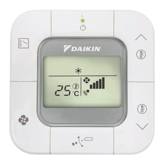
WIRED REMOTE
CONTROLLER
Installation and Operation manual
• Thank you for purchasing this product.
• This manual describes safety precautions required for the use of the product.
Read this manual carefully and be sure you understand the
information before installing and using the product.
Keep this manual where it is readily accessible after reading it through.
If another user operates the product in the future, be sure to hand over this
manual to the new user.
Refer to the installation and operation manuals attached to the indoor and
outdoor units, etc.
BRC2E61
Advertisement
Table of Contents

Related Manuals for Daikin BRC2E61


Summary of Contents for Daikin BRC2E61
- Page 1 WIRED REMOTE CONTROLLER Installation and Operation manual BRC2E61 • Thank you for purchasing this product. • This manual describes safety precautions required for the use of the product. Read this manual carefully and be sure you understand the information before installing and using the product.
- Page 2 „ Disposal requirements Your product and the batteries supplied with the controller are marked with this symbol. This symbol means that electrical and electronic products and batteries shall not be mixed with unsorted household waste. For batteries, a chemical symbol can be printed beneath the symbol.
-
Page 3: Table Of Contents
CONTENTS 1. Safety precautions ..........2 For the installer ................2 For the user ................. 4 2. Accessories ............. 5 3. Button locations and descriptions ......5 4. Names and functions ..........6 4.1 Basic screen ............... 6 For the installer 5. -
Page 4: Safety Precautions
1. Safety precautions „ Also refer to the installation and operation manuals attached to the indoor unit. Please read these “Safety precautions” carefully before installing and using the remote controller. • This product is not intended for use by children or infirm persons without supervision. Children should be supervised to ensure that they do not play with the product. • This manual classifies the precautions into WARNINGS and CAUTIONS. Be sure to follow all the precautions below: They are all important for ensuring safety. Indicates a potentially hazardous situation which, if not avoided, could WARNING result in death or serious injury. Indicates a potentially hazardous situation which, if not avoided, may CAUTION result in minor or moderate injury. - Page 5 WARNING Do not disassembly, reconstruct or repair. Electric shock or a fire may cause. Make sure that all wiring is secured, using the specified wirings and ensuring that external forces do not act on the terminal connections or wirings. Improper connections or fixing may cause an overheat or a fire. The choice of materials and installations must comply with the applicable national and international standards. CAUTION To avoid electric shock due to entry of water or insects, fill the wiring through hole with putty. Do not operate with wet hands to avoid electric shock. Do not wash the remote controller with water. It may result in electric shock or a fire. Install the air conditioner, power supply wiring, remote controller wiring and transmission wiring at least 1 meter away from televisions or radios to prevent image interference or noise. (Depending on the radio waves, a distance of 1 meter may not be sufficient to eliminate the noise.) Do not install the remote controller in the following locations: 1. W here there is oil mist, oil spray or vapour for example a kitchen. Resin parts may deteriorate and fall off. 2. W here corrosive gas, such as sulfurous acid gas, is produced. 3. W here there is machinery which emits electromagnetic waves. Electromagnetic waves may disturb the control system, and cause a malfunction of the equipment. 4. W here flammable gas may leak, where there is carbon fibre or ignitable dust suspensions in the air, or where volatile flammables such as thinner or gasoline are handled. Operating the unit in such conditions may result in a fire. 5. H igh temperature area or directly flamed point.
-
Page 6: For The User
For the user WARNING Do not install the remote controller by yourself. Improper installation may result in electric shock or a fire. Consult your local dealer. Do not modify or repair the remote controller. It may result in electric shock or a fire. Consult your local dealer. Do not relocate or reinstall the remote controller by yourself. Improper installation may result in electric shock or a fire. -
Page 7: Accessories
2. Accessories The following accessories are included. Wired remote controller Wood screw Small screw Installation & Operation manual (M3.5 × 16) (M4 × 16) (1 pc.) (1 pc.) (2 pcs.) (2 pcs.) (1 pc.) 3. Button locations and descriptions 1. ON/OFF button 2. Operation lamp (Green) 3. Mode Selector button 6. Temperature 4. -
Page 8: Names And Functions
4. Names and functions 4.1 Basic screen 4. DISPLAY “ ” (NON 1. DISPLAY “ ” (CHANGEOVER FUNCTION DISPLAY) UNDER CONTROL) If the particular function is not available, It is impossible to changeover Heat/Cool with pressing the button may display the words the remote controller when it shows this “ ” for a few seconds. display. (As for details, see “SETTING OF When running multiple units simultaneously, MASTER REMOTE CONTROLLER” in the the “ ” message will only be operation manual attached to the indoor unit.) appear if none of the indoor units is equipped with the function. If even on unit is equipped 2. - Page 9 8. DISPLAY “ ” (UNIT NO. 11. DISPLAY “ ” (AIRFLOW MODE) DIRECTION) During fi eld setting (setting per indoor unit The display shows when the airfl ow direction during group control function), the display and swing are set. This icon is not displayed if shows the selected unit no. the indoor unit does not have a function to set airfl ow directions. 9. DISPLAY “ ” (VENTILATION/ AIR CLEANING) 12.
-
Page 10: For The Installer
For the installer 5. Remote controller installation procedure 1) Determine where to install the remote controller. Make sure to follow “1. Safety precautions” when determining the location. 2) Determine the direction of controller wiring outlet (Top right outlet, Right outlet, Bottom centre outlet). 1) Top right outlet Front side Back side Cut away the thin area (hatched area) with nippers or the like and then remove burrs... - Page 11 3) Conduct wiring CAUTION 1. S witch box and transmission wiring are not attached. 2. Do not directly touch the PCB (Printed Circuit Board). Wiring specifications Wiring Type Sheathed vinyl cord or cable (2 cores) (*1) Wiring Size 0.75~1.25 mm Wiring Length Max. 500 m (*2) * 1. S ome countries may require a shielded wiring. Refer to the installation manual attached to the indoor unit. * 2. T his will be the total extended length in the system when doing group control.
- Page 12 „ Right outlet Upper case Lower case Indoor unit P1 P2 „ Bottom centre outlet Upper case Lower case Indoor unit P1 P2 CAUTION Perform the wiring at a distance from the power line so as not to receive electrical noise (external noise).
- Page 13 4) Fix the lower case to a wall. In case of wiring a remote controller through Top right outlet, Right outlet, or Bottom centre outlet, perform wiring though the outlet hole in the lower case before installing on the wall. Secure by using the attached wood screws (2 pcs.) or small screws (2 pcs.). Fix the top screw hole first, then fix the bottom screw hole. Wood screws (M3.5×16) or Small screws (M4×16) CAUTION • Select as flat a place as possible for the installation face. • Do not tighten the installation screws too much so as not to deform the lower case.
- Page 14 5) Install the upper case in the original position. • Align the upper case with the tabs on the lower case (4 points), then insert and install the upper case. Carefully check that there is no gap between the upper and lower cases when they are closed. No gap There is a gap. Good Wrong If there is a gap, remove the upper case and rearrange wire harness position then reinstall the upper case. (For the removal method of the upper case, see the note.) • Install the wiring with care to prevent pinching. • Peel off the protective sheet which is attached to the upper case. Note: When removing the upper case Insert a screwdriver in the recess of lower case to remove the upper case (2 points). Upper case Remote controller PCB is installed on the upper case. Take care not to damage the PCB Screwdriver with the screwdriver.
-
Page 15: Power-On
Connection diagram “Group control: main controller + sub controller” on page 20. (1) Factory set: MASTER (2) Move to SLAVE [Main/Sub remote controller] “ ” is displayed after turning on the power. The air conditioner will check the connection. • If errors are detected, the relevant error code blinks on the screen. Please see more details about error codes at https://www.daikin.co.th/en/service-error-code After correcting the error, the basic screen is displayed. • If sub remote controller is not set when turning on the power in the case of indoor units controlled by 2 remote controllers. In case the screen display shows “ ”, turn off the ‹ power of the remote controller and breaker of air conditioner. Then change the SS1 switch from the... -
Page 16: Field Settings
7. Field settings [Basic screen] Press and hold both the Mode Selector button ( ) and the Temperature Setting (down) button ) for 4 seconds or longer. Press and hold 2 buttons for 4 seconds or longer. [Field setting mode screen] Select the desired “Mode No.” by using the Airflow Direction Adjustment button ( For commonly used field setting items, refer to the table on page 16. - Page 17 After all setting changes are completed, [Initialization screen] press both the Mode Selector button ) and the Temperature Setting (down) button ( ) for 1 second. “ ” is displayed during initialization. After the initialization, the basic screen returns. [Basic screen] CAUTION • When an optional accessory is installed on the indoor unit, settings of the indoor unit may be changed. Refer to the manual of the optional accessory. • For field setting details of the outdoor unit, refer to the installation manual attached to the outdoor unit.
- Page 18 [Commonly used field setting items] SECOND CODE No. Mode No. FIRST Description of setting Note 1) CODE No. Ultra-long- Approx. Approx. Filter Contamination -Heavy/Light life type 10,000 Hrs 5,000 Hrs (Setting for spacing time of display time to clean air filter) Long life Approx. Approx. – Note 3) (Setting for when filter contamination Filter 2,500 Hrs 1,250 Hrs is heavy, and spacing time of display Standard Approx. Approx.
-
Page 19: Test Operation Method (In The Case Of Split System)
8. Test operation method (in the case of SPLIT system) • In the case of VRV system, refer to the manual attached to the outdoor unit. Also refer to the installation manuals attached to the indoor unit and the outdoor unit. • Check that wiring work of the indoor unit and the outdoor unit is completed. • Check that control box lid of the indoor unit and the outer panel and piping cover of the outdoor unit are closed. • After refrigerant piping, drain piping and electric wiring are completed, clean the inside of the indoor unit and decoration panel. • Perform the test operation according to following procedure. To protect the compressor, turn on the power to the outdoor unit at least 6 hours prior to test operation. - Page 20 Check the operation status of the remote controller by checking if the green lamp on the ON/OFF button lights up or not. • If the remote controller is ON (Green lamp lights up), continue to step 6). • If the remote controller is OFF (Green lamp doesn’t light up), press the ON/ OFF button within 10 seconds after “ ” is displayed on the basic screen. Check the operation of the buttons by pressing the following buttons • Press the Airflow Direction Adjustment button ( ) for setting airflow. • Press the Mode Selector button ) for setting operation mode. • Press the Fan Speed Control button ) for setting fan speed.
-
Page 21: Connection Diagram
9. Connection diagram „ Typical layout „ Typical layout for group control P1 P2 P1 P2 P1 P2 P1 P2 Note: • To enable the rotation function, group control is required. • When using group control, every unit is automatically assigned an address (i.e. Unit Number). In case the rotation function is enabled, this number determined the rotation order. For instructions on how to change the Unit Number, contact your local dealer. - Page 22 „ Group control: main controller + sub controller P1 P2 P1 P2 P1 P2 P1 P2 P1 P2 [Main controller] [Sub controller] „ Controller + DIII central control equipment F1 F2 P1 P2 F1 F2 P1 P2 Note: If the controller is used together with DIII central control equipment, then... • ... the schedule timer function can be restricted. • ... do not enable setback mode.
-
Page 23: For The User
For the user 10. Basic operation 10.1 Cool/Heat/Auto/Fan operation Preparation • For mechanical protection purpose, turn on the power to the air conditioner at least 6 hours before starting the operation. Operation • Press the Mode Selector button ( ) several times until the desired mode (Cool, Heat, Fan or Auto) is selected. Unavailable operation modes are not displayed. ‹ Only the Cool or Fan mode can be selected if the air conditioner ‹ is a cooling only model. Basic screen Note: • The Cooling or Heating mode cannot be selected if the icon “... - Page 24 [Airflow rate (Airflow level/Fan speed) setting] (lv.1) (lv.2) (lv.3) • To select the fan speed level, press the Fan Speed Control button ( For equipment protection purpose, the indoor ‹ (Auto) (lv.5) (lv.4) unit may control airflow rate automatically. According to the room temperature, the indoor ‹ unit may control airflow rate automatically. The fan may stop operating, which, however, is not a failure. It may take time until a change of the airflow ‹ rate is completed. In Auto setting, the airflow rate is adjusted ‹ automatically according to set temperature and room temperature. In Fan mode, the airflow rate setting is always at Lv.5.
- Page 25 Characteristic of Cooling operation (in Cool/Auto mode) • When operating continuously at horizontally or downward airflow direction, air blows in the automatically set direction for a period of time to prevent condensation on the horizontal flap. (The remote controller displays the airflow direction that is set.) • If the Cooling operation is used when the room temperature is low, frost forms on the heat exchanger of the indoor unit. This can decrease the cooling capacity. In this case, the air conditioner automatically switches to the Defrost operation for a while. During the Defrost operation, the low airflow rate or a gentle wind is used to prevent the discharge of melt water. (The remote controller displays the airflow rate that is set.) • When the outdoor air temperature is high, it takes some time until the room temperature reaches the set temperature. Characteristic of Heating operation (in Heat/Auto mode) Starting operation • Heating operation generally requires a longer time to reach the set temperature compared with Cooling operation. It is recommended to start operating in advance by utilizing the timer.
-
Page 26: Dry Operation
10.2 Dry operation Preparation • For mechanical protection purpose, turn on the power to the air conditioner at least 6 hours before starting the operation. • Dry mode may not to be selected, if the remote controller has no eligibility to select Cooling/Heating mode (Refer to page 26 for details). Operation • Press the Mode Selector button ( ) several times until Dry mode is selected. Dry mode may not be available depending on ‹... -
Page 27: Setting The Cool/Heat Selection Eligibility (Vrv Only)
10.3 Setting the Cool/Heat selection eligibility (VRV only) Refer to “Cool/Heat selection eligibility” on page 26 for an explanation of the Setting Changes Cool/Heat selection eligibility. • Press the Mode Selector button ( ) on the remote controller that has Cool/Heat selection eligibility for at least 4 seconds. A remote controller will not display “ ” (Changeover Under Control) if a Cool/Heat selection eligibility is granted to the remote controller. - Page 28 • Press the Mode Selector button ( ) on the remote controller that has the Cool/Heat selection eligibility (the remote controller without the icon “ ”) several times until the desired mode is selected. The display will change to “Fan”, “Dry”, “Auto”, “Cool”, “Heat” each time the button is pressed. • The display “Auto” will appear for the Heat Recovery system only. Simultaneously, the other remote controllers will follow suit and change the display automatically. Cool/Heat selection eligibility • The “Cool”, “Heat”, “Auto” can be set by only the remote controller that has the Cool/Heat selection eligibility. (The display “Auto” will appear for the Heat Recovery System only.) The remote controller with Other remote controllers Set to “Cool”, “Heat”, the selection eligibility (Icon “...
- Page 29 Precautions for Setting Cool/Heat selection eligibility • The Cool/Heat selection eligibility needs to be set for a single remote controller in the following case. (Heat Pump System) (Heat Recovery System) BS (Branch Selector) unit: The BS unit is used for Cool or Heat mode selection. Indoor unit Indoor unit A number of indoor units are A number of indoor units are connected connected to a single outdoor unit.
-
Page 30: Program Timer Operation
10.4 Program timer operation Operate in the following order. • The timer is operated in the following two ways. Programming the stop time ( ..The air conditioner stops operating after the set time has elapsed. Programming the start time ( ..The air conditioner starts operating after the set time has elapsed. • The start and the stop time can be simultaneously programmed. - Page 31 ON Timer mode setting • Press both the Fan Speed Control button ( and Temperature Setting (up) button ( simultaneously to enter timer mode setting. The display “ ” blinks. • Press the Temperature Setting (up/down) button ) and set the time for starting the air conditioner.
-
Page 32: Maintenance
11. Maintenance 11.1 Cleaning of the remote controller • Wipe the surface part of the remote controller with a dry cloth when it becomes dirty. • If the dirt on the surface cannot be removed, soak the cloth in neutral detergent diluted with water, squeeze the cloth tightly, and clean the surface. Wipe the surface with a dry cloth then. Note: • Do not use any paint thinner, organic solvent, or strong acid. WARNING • Do not use flammable materials (e.g., hairspray or insecticide) near the air conditioner. Do not clean remote controller with organic solvents such as benzine or paint thinner. The use of organic solvents may cause crack damage to the product, electric shock or a fire. CAUTION • Do not wash the remote controller. Doing so may cause electric leakage and result in electric shock or a fire. • Be sure to stop the operation of the air conditioner and turn off the power at the time of maintenance. Failure to do so may result in electric shock or injury. -
Page 33: Reference Information
12. Reference Information 12.1 Malfunction (Error) code display In case of malfunction, the error code will be displayed on the screen. Please contact your local dealer and inform them of the error code for repair. WARNING • When the air conditioner is malfunctioning (e.g., giving off a burning odor), stop the air conditioner and turn off the power. Continued operation under such circumstances may result in failure, electric shock or a fire. Contact your local dealer. 12.2 After-sales service WARNING • Do not disassemble, modify, or repair the remote controller. It may cause electric shock or a fire. Consult your local dealer. • Do not relocate or reinstall the remote controller by yourself. - Page 34 MEMO...
- Page 36 The two-dimensional bar code is a manufacturing code. 4P543053-1C M18N065B (1906) HT...
Need help?
Do you have a question about the BRC2E61 and is the answer not in the manual?
Questions and answers