Tiso BASTION-M Operating Manual

Tiso BASTION-M Operating Manual

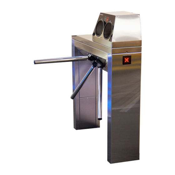
Servo-operated tripod turnstiles
Table of Contents

Advertisement

"TiSO-PRODUCTION" LTD
SERVO-OPERATED TRIPOD TURNSTILES
CENTURION-M
BASTION-M
SKULL-M
TWIX-M
OPERATION MANUAL
2018

Advertisement

Table of Contents
loading

Summary of Contents for Tiso BASTION-M

  • Page 1 “TiSO-PRODUCTION” LTD SERVO-OPERATED TRIPOD TURNSTILES CENTURION-M BASTION-M SKULL-M TWIX-M OPERATION MANUAL 2018...
  • Page 2: Table Of Contents

    Annex А..................................41 Design, overall and installation dimensions of the "СENTURION-M" type turnstile..........41 Design, overall and installation dimensions of the "BASTION-M" type turnstile..........42 Design, overall and installation dimensions of the "SKULL-M" type turnstile............43 Design, overall and installation dimensions of the "TWIX-M" type turnstile............44 Annex B: Control panel and connection diagram....................
  • Page 3: Introduction

    INTRODUCTION This Operation Manual (hereinafter referred to as OM) covers the servo-operated turnstile (hereinafter referred to as the "turnstile"). The Operation Manual contains information about design, specifications, installation for proper operation and maintenance of the turnstile. This Operation Manual is prepared in compliance with the specification requirements ТY Y 31.6-32421280-004:2010.
  • Page 4 The tripod type turnstile reference designation is given in Table 1. Table 1 Name Code Designation CENTURION-M T3.TCC.ХE AUIA.095 OM BASTION-M T3.TCY.ХE AUIA.097 OM SKULL-M T3.TCG.ХE AUIA.096 OM TWIX-M T3.TYK.ХE AUIA.137 OM Example of reference designation of the servo-operated turnstile with solid body of brushed...
  • Page 5 WARNINGS TO THE CUSTOMER ON SAFE OPERATION OF THE TURNSTILE These warnings are designed for ensuring of safety during operation of the turnstile to prevent violation of safety characteristics by improper installation or operation. These warnings are aimed at drawing attention of the customer to safety problems. GENERAL WARNINGS The Operation Manual is an integral part of the product and it shall be handed over to the customer.
  • Page 6: Description And Operation

    1. DESCRIPTION AND OPERATION 1.1 General Information and Purpose 1.1.1 Turnstile purpose: The turnstile is designed for arrangement of individual pedestrian access at access points of industrial enterprises, banks, stadiums, administrative facilities etc. driven by control signals of access control system (from keypad, proximity card readers) or manually (from wire control panel).
  • Page 7: Specifications

    Continued Table 3 disturbing normal operation of the equipment installed in turnstiles In enclosed spaces in the absence of direct impact of precipitations and Installation site solar radiation Vertical, deviation from vertical position no more than 1º to any side Operating position is acceptable 1.1.5 Reliability indices:...
  • Page 8 CENTURION-M BASTION-M SKULL-M TWIX-M 1 - turnstile rack; 6 - hub; 2 - LED display; 7 - barrier rod; 3 - card reader location; 8 - lock door; 4 - upper lid; 9 - control panel; 5 - control mechanism;...
  • Page 9 (See Fig.2). Fig.2. – Tripod turnstile scope of delivery 1.3.3 The turnstile design, overall and installation dimensions (See Fig.3) CENTURION-M BASTION-M SKULL-M TWIX-M * Carrier sleeve size Fig. 3 - Tripod turnstile dimensions Is not included in the turnstile scope of delivery - to be equipped by the custoner, if appropriate...
  • Page 10: Design And Operation

    V network and control panel are mounted, are fixed inside the turnstile post 1 (See Fig.1) under the removable door 8 (for the turnstiles CENTURION-M and BASTION-M) or removable lid 4 (for the turnstiles TWIX and SKULL). Controller controls the turnstile motor analyzing signals from speed and position sensors as well as provides the motor protection against overloads.
  • Page 11 1.4.1.3 The tripod turnstile control mechanism design is shown in Figure 5. Top view Front view 1 – gear motor; 6 – hub shaft; 2 – position sensor; 7 – mechanism body; 3 – antipanic device; 8 – hub with barrier rods; 4 –...
  • Page 12 1.4.3 Turnstile principle of operation 1.4.3.1 Turnstile operation modes: 1) single access in the direction “A” or “B”; 2) locking; 3) free access in the direction “A” or “B”. 4) "PANIC" mode 1.4.3.2 In the initial state, when the turnstile is deenergized, barrier rods are locked from rotation and access is barred.
  • Page 13: Instrumentation, Tools And Accessories

    After the signal is deactivated from the input (in1) or deactivation of the panic mode from control panel, a barrier rod is automatically reset to its initial position. Before turning on the power and turning off the panic, you need to manually check the verticality of the barrier rod (if necessary, lower the leash manually to the stop).
  • Page 14: Description And Operation Of Controllers As Components Of The Turnstile

    1.6 Description and operation of controllers as components of the turnstile 1.6.1 Motorized mechanism controller РСВ.201.01.00.00 The controller is designed for acquisition of commands from the turnstile controller PCB.112.21.20.00 and generation of signals controlling motor and the motorized mechanism locking solenoids. 1.6.1.1 The controller is assembled on the (85 х...
  • Page 15 Fig. 9 – Appearance of the motorized mechanism controller РСВ.201.01.00.00 1.6.1.3 Description of controller operation The controller controles the turnstile DC motor and the turnstile mechanism locking solenoids according to the logic entered into program depending on incoming commands, rotor position, rotation speed and motor current.
  • Page 16 Table 7 Connector/ Purpose Designation Direction Signal parameters and contact No description ENTRY Not applicable X1/1 «0» ENTRY Not applicable X1/2 (0 1,7) ; ENTRY Selection of turnstile type X1/3 «1» ENTRY Not applicable X1/4 (3,7 5) ; ENTRY X1/5 ENTRY X1/6 –...
  • Page 17 1.6.2.1 The controller is assembled on board (104х68) and designed for installation inside the turnstile body or power supply box. The controller appearance is shown in Figure 6. 19 LEDs are installed on the controller board. Their purpose is as follows: •...
  • Page 18 Fig. 10 – Appearance of the turnstile controller РСВ.112.21.20.00  SINGLE ACCESS IN ONE DIRECTION;  FREE ACCESS IN ONE DIRECTION;  LOCKING OF ACCESS. Other operating modes are combinations of various or similar modes in different directions:  Single access in one direction and any mode in opposite direction. ...
  • Page 19 The controller is switched to “SINGLE ACCESS IN ONE DIRECTION”, if in the INITIAL STATE it receives “TO BE OPENED А/В" command (i.e. active level of signal is sent to input “INP4” or “INP5”). In this case the turnstile is open within action period of signal. The command can also be sent delay of WAITING FOR START OF ACCESS.
  • Page 20 1.6.2.3.4 AUTHORIZATION OF SINGLE ACCESS IN TWO DIRECTIONS Since the turnstile having one rotor can't rotate in two directions simultaneously, the controller can only unlock rotor in two directions and after access in one of directions is started, the reverse direction will be closed.
  • Page 21 Connector/ Signal parameters Purpose Designation Direction and description contact No «SWITCHING TO PANIC ENTRY ХТ1/1 INP1 («PANIC») STATE» command INP2 "TO BE OPENED FOR ENTRY («TO BE OPENED ХТ1/2 SINGLE ACCESS" in 1) logic «0» A») pulse mode command. (0 ÷ 2,2)V When this command is 2) Logic «1»...
  • Page 22 Continued Table 8 Signal is generated by INP1 («PANIC») EXIT ХТ2/8 controller when “PANIC” function is activated 1) Logical «0» (0 ÷ 2,2) V ENTRY ХТ3/1 OPTO1 2) Logical «1» It is used for acquisition of ENTRY ХТ3/2 (3 ÷ 5) V OPTO2 data about the turnstile 3)Active level of...
  • Page 23 Continued Table 8 Interface RS-485 It is used for data ХТ3/14 RSА transmission via serial port Interface RS-485 ХТ3/15 RSВ RS-485 SHIELD ХТ3/16 It is used for energization 1) Type of output - of arrier rod EXIT ХТ4/1 open collector. - MGA system 2) Peak voltage on...
  • Page 24: Intended Use

    2 INTENDED USE 2.1 Operation limitations 2.1.1 The turnstile must be used in the environment specified in p. 1.1.5 of this document subject to the specifications listed in section 1.2. IT IS FORBIDDEN: 1) TO MISUSE THE TURNSTILE (See section 1 "DESCRIPTION AND OPERATION");...
  • Page 25 WARNING: The turnstile damages occurred during transportation are not covered by the manufacturer's warranty liabilities. 2.2.3 Safety Measures:  Installation to be performed only by the persons briefed on safety and studied this manual;  Only serviceable tools to be used during installation of the turnstile; ...
  • Page 26 Side view ENCLOSURE Top view ENCLOSURE Fig.12 – Tripod turnstile layout (conditionally)
  • Page 27 2.2.5 Installation procedure The turnstile installation procedure is as follows: 1) The package integrity to be checked prior to unpacking. If package is damaged, then damages to be fixed (picture to be taken, damage report to be made). 2) The turnstiled to be unpacked and inspected for defects and damages as well as completeness to be checked according to the turnstile data sheet;...
  • Page 28 б) BASTION-M в) TWIX-M г) SKULL-M Fig. 13 – Tripod type turnstile installation marking...
  • Page 29 7) Installation of hub on the tripod turnstile (Through the example of the turnstile AUIA.095-10 "CENTURION-M"). (For the sake of convenience installation of the hub with barrier rods is acceptable at the end of installation and connection of the turnstile): a) The hub (1) barrier rods (2) to be set out manually (See Fig.
  • Page 30 4.Card reader to be installed; 5.To be secured with anchors. Fig. 15 – General view of the "CENTURION-M" and "BASTION-M" tripod turnstiles assembly Two turnstile rack doors to be removed by uncrewing one screw fastening door to the body to access to the "TWIX-M" tripod turnstile base fixation holes.
  • Page 31 The lid to be removed by unscrewing 4 screws on butt ends (Fig. 15 ) to access to the "SKULL-M" tripod turnstile fixation and service holes as well as terminal blocks (See Fig.17). Fig. 17 – General view of the "SKULL-M" tripod turnstile assembly WARNING: ...
  • Page 32: Preparation For Use

    b) Control panel link cable to be connected to the terminals (Fig.18): - P (Power) – control panel power supply +12V - G (GND) - control panel common wire; - A (RSA) - RSA wire of control panel link line; - B (RSB) - RSB wire of control panel link line;...
  • Page 33 hen the turnstile is commissioned it is necessary to perform the inspections specified in 2.3.2.1 Table 9. The wiring diagram according to Annex C and the control panel according to Annex be used during inspection. Table 9 Turnstile operation LED display Operation mode setting mode 1.
  • Page 34: Contingency Actions

    Continued Table 9 2.3.2.2 After the turnstile is inspected it is ready for long-term operation. 2.4 Contingency actions For emergency human escape (in case of fire, acts of God etc.) and enabling free access the turnstile to be unlocked from control panel by issuing the relevant command. Antipanic device to be used for full opening of access way.
  • Page 35: Safety Measures

    3.1.3 The turnstile to be installed and operated only by the qualified safety briefed staff having the relevant class of permit to work with electrical facilities with voltage up to 1000V, awaring of this OM, the turnstile design and principle of operation.
  • Page 36: Routine Maintenance

    - visual inspection of connecting, network and earthing cables condition; - verification of the turnstile performance during manual control in the modes specified in Table 9 or as part of ACS when pendants, identification cards are used; - verification of reliability of the turnstile screw joints and earthing connections - to be tightened, if applicable;...
  • Page 37 Table 12 Make sure that ACS provides proper activation signal...
  • Page 38: Postrepair Checkout

    Continued Table 12 4.3 Postrepair checkout The turnstile performance to be checked after repair according to paragraph 2.3.2 of this OM.
  • Page 39: Transportation And Storage

    5 TRANSPORTATION AND STORAGE 5.1 Turnstile storage It is forbidden to subject the turnstile to jerks and impacts during storage. Transportation trolleys to be used for handling of the turnstile. In storage facilities there should not be aggressive gases and vapours causing metal corrosion. Air temperature during storage should not be below +5 С...
  • Page 40 7.6 The relationships between the Manufacturer and the Customer under the warranty liabilities to be regulated by the applicable law of Ukraine, concluded purchase contracts and these warranty liabilities. "TiSO-PRODUCTION" LTD 14 Promyshlennaya str., 02088 Kiev, Ukraine Tel.: +38 (044) 291-21-01 Tel../Fax: +38 (044) 291-21-02...
  • Page 41: Annex А

    Annex А (mandatory) Design, overall and installation dimensions of the "СENTURION-M" type turnstile Figure А.1 – Tripod turnstile "СENTURION-M"...
  • Page 42: Design, Overall And Installation Dimensions Of The "Bastion-M" Type Turnstile

    Continued Annex А (mandatory) Design, overall and installation dimensions of the turnstile "BASTION-M" Figure А.2 – Tripod turnstile "BASTION-M"...
  • Page 43: Design, Overall And Installation Dimensions Of The "Skull-M" Type Turnstile

    Continued Annex А (mandatory) Design, overall and installation dimensions of the turnstile "SKULL-M" Figure А.3 – Tripod turnstile "SKULL-M"...
  • Page 44: Design, Overall And Installation Dimensions Of The "Twix-M" Type Turnstile

    Continued Annex А (mandatory) Design, overall and installation dimensions of the turnstile "TWIX-M" Figure А.4 – Tripod turnstile "TWIX-M"...
  • Page 45: Annex B: Control Panel And Connection Diagram

    Annex B (mandatory) Control panel and connection diagram 1 – control panel housing; 5 – "FREE ACCESS" mode control button; 2 – "SINGLE ACCESS" mode control button 6 – "PANIC" mode control button; 3 – front plate; 7 – access direction LED display; 4 –...
  • Page 46 Continued Annex B Control panel and connection diagram “P” “G” “A” “B” Figure B.2 – Control panel AUIA.114.02.00.00 connection diagram...
  • Page 47: Annex C: Wiring Diagram Of The Servo-Operated Tripod Type Turnstile

    Annex C (mandatory) Servo-operated tripod turnstile wiring diagram CONTROL MECHANISM Control panel AUIA195 A UIA195 XP1 PCB +12V CONTROLLER SPEED CONTROLLER PCB 112.21.20.00 PCB 201.01.00.00 ANGLE 1 ANGLE 2 INP 1 OPTO 1 PANIC ZERO 3 INP 2 OPTO 2 IN 1 GRN 1 OPEN "A"...
  • Page 48: Annex D 1: Wiring Diagram Of The Turnstile Connection To Access Control System (Acs) In Pulse Mode

    Annex D.1 (mandatory) Wiring diagram of the turnstile connection to access control system (ACS) in pulse mode inp1- "PANIC" inp2- "TO BE OPENED A" in pulse mode. When command is issued entry is activated for 5 sec. inp3- " TO BE OPENED B" in pulse mode. When command is issued entry is activated for 5 sec. inp4- "TO BE OPENED A".
  • Page 49: Annex D 2: Wiring Diagram Of The Turnstile Connection To Access Control System (Acs) In Hold Mode

    Annex D.2 (mandatory) Wiring diagram of the turnstile connection to access control system (ACS) in hold mode inp1- "PANIC" inp2- "TO BE OPENED A" in pulse mode. When command is issued entry is activated for 5 sec. inp3- " TO BE OPENED B" in pulse mode. When command is issued entry is activated for 5 sec. inp4- "TO BE OPENED A".
  • Page 50: Annex D 3: Wiring Diagram Of The Turnstile Connection To Fire Alarm System (Fas)

    Annex D.3 (mandatory) Wiring diagram of the turnstile connection to fire alarm system (FAS) inp1- "PANIC" inp2- "TO BE OPENED A" in pulse mode. When command is issued entry is activated for 5 sec. inp3- " TO BE OPENED B" in pulse mode. When command is issued entry is activated for 5 sec. inp4- "TO BE OPENED A".
  • Page 51: Annex D 4: Wiring Diagram Of The Turnstile Connection To Fire Alarm System (Fas)

    Annex D. (mandatory) Wiring diagram of the turnstile connection to fire alarm system (FAS) inp1- "PANIC" inp2- "TO BE OPENED A" in pulse mode. When command is issued entry is activated for 5 sec. inp3- " TO BE OPENED B" in pulse mode. When command is issued entry is activated for 5 sec.
  • Page 52: Annex D 5: Diagram Of The Turnstile Connection To Control Panel

    Annex D.5 (mandatory) Wiring diagram of the turnstile connection to control panel Figure D.5 – Wiring diagram of the turnstile connection to control panel...

This manual is also suitable for:

Twix-mCenturion-mSkull-m

Table of Contents