Table of Contents
Advertisement
Quick Links
Advertisement
Table of Contents

Related Manuals for PCE Instruments PCE-LOC 20


Summary of Contents for PCE Instruments PCE-LOC 20
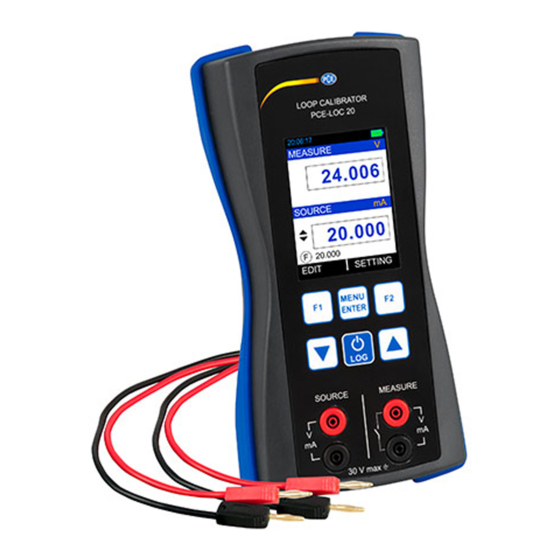
- Page 1 PCE-LOC 20 PCE-LOC 20 Loop Calibrator User manuals in various languages (français, italiano, español, português, nederlands, türk, polski, русский, 中文) can be found by using our product search on: www.pce-instruments.com Last change: 10 August 2018 v1.0 © PCE Instruments...
-
Page 2: Table Of Contents
Contents Safety notes ................... 1 PCE-LOC 20 Hardware Parts and Accessories ........2 Unpacking and Inspection ....................2 Operational Sections and Connections ................3 Power Options........................8 Battery ..........................8 Start Up and Basic Operations ............9 Power ON or OFF ......................9 User Interface ........................ -
Page 3: Safety Notes
We expressly point to our general guarantee terms which can be found in our general terms of business. If you have any questions please contact PCE Instruments. The contact details can be found at the end of this manual. © PCE Instruments... -
Page 4: Pce-Loc 20 Hardware Parts And Accessories
PCE-LOC 20 Hardware Parts and Accessories Unpacking and Inspection At the factory each new PCE-LOC 20 passes a careful inspection. It should be free of scrapes and scratches and in proper operation order upon receipt. The recipient should, however, inspect the unit for any damage that may have occurred during transit. -
Page 5: Operational Sections And Connections
All sections and connections are presented in detail on the next pages. Note: Keep in mind that the next picture (as well as all pictures of PCE-LOC 20 in this manual) has an example configuration of modules. The configuration of your PCE-LOC 20 may vary significantly from the one in the picture. - Page 6 Current Generation The PCE-LOC 20 is able to generate current both in source and sink mode. In source mode, the PCE-LOC 20 provides the supply power to the loop. In sink mode, an external power supply is used and the PCE-LOC 20 controls the current flow.
- Page 7 Current Measurement In this mode, the PCE-LOC 20 is not providing any supply voltage. For proper measurement, the external device should be capable of providing the voltage supply. If the external device is not capable, an external Power Supply should be connected in series.
- Page 8 Switch Test The PCE-LOC 20 is capable of detecting switch’s state both when the switch is free of external potential or switches with DC voltages within the range 0 V … +30 V. Switch Mode: 2V (24VDC, 30mA) Switch Mode: Voltage Trigger KeyPad The PCE-LOC 20 has six different keys.
- Page 9 • Supporting 262K colors USB Connection • The USB connection is located at the top of the PCE-LOC 20. It is a USB mini B-Type female connector. • It can be used for PC communication and for charging the device.
-
Page 10: Power Options
(40 %) and a short Timeout. The maximum operating time without recharging varies depending on the usage and brightness setting of the display light. Also the generated output current and the usage of the 24 V transmitter supply affect the maximum operating time. © PCE Instruments... -
Page 11: Start Up And Basic Operations
• Do not leave the PCE-LOC 20 without a battery pack or an empty battery for a long time. The PCE-LOC 20 may lose its settings if it is left without a support voltage for an extended period. Start Up and Basic Operations... - Page 12 Not all possible elements are included in the previous picture, but the most important ones are discussed in the following chapters. The Status Bar The status bar at the top of the display is visible only in RUN Page. It is divided into five main sections. © PCE Instruments...
- Page 13 % is >= 50%, >= 20 and <20 respectively. Data Logging Enable Status Indicator Icon is visible if data logging is enabled and will flash when a data log is stored to the memory © PCE Instruments...
- Page 14 Shows the One of the available Addition Information This can be selected by Additional Info. 2 List in MENU → DISPLAY → MEASURE page. This will disable if Bargraph is selected as Additional Info1 in MENU → DISPLAY →MEASURE page. © PCE Instruments...
- Page 15 This can be selected by Additional Info. 1 List in MENU → DISPLAY → SOURCE page. STEP/RAMP Icon Shows the Icon indicating STEP/RAMP mode. Manual Rising Step Ramp Falling Step UP Ramp Step Ramp Hold DOWN @ 0% Ramp Hold @ 100% © PCE Instruments...
- Page 16 Max-Min Displays the Maximum-Minimum value found after measurement was started or Maximum-Minimum was reset. Cumulative Average Displays the Cumulative Average value found after a measurement was started or Cumulative Average was reset. © PCE Instruments...
- Page 17 The Percentage Value in (0.00% … 100.00%) according to Percentage Value Output Value. Actual Value The Raw Output Value without any scaling This will appear only if Main Display in MENU → DISPLAY → SOURCE is set to PERCENTAGE/SCALED. © PCE Instruments...
- Page 18 Displays the Source Reading value after the switch CLOSE was detected. Display Operations Mainly, four types of widgets are available in the Device Menu. ListBox EditBox iii. CheckBox RadioButtonBox The below section will show how to change the value of different widgets. © PCE Instruments...
- Page 19 To edit the value of an EditBox, press F1 key. After that EditBox enters Edit mode where F1 and F2 keys work as shifter. User can shift to desired digit and using UP or DOWN key digit value can be incremented or decremented. The modified value can be saved using MENU/ENT key. © PCE Instruments...
- Page 20 The below figure shows the example how to change decimal point of the Input Scaled High(100%) Range To change the sign of the value, shift to the sign digit and pressing UP or DOWN key will toggle the sign. © PCE Instruments...
- Page 21 In RadioButtonBox the other option can be selected by pressing MENU/ENT key on that option. When pressing this key the new option will be selected and the other option will be disabled. Below an example is given, How to change Source Type from STEP to Ramp. © PCE Instruments...
-
Page 22: Menu Layout
Contains Parameters related to General Settings of the device like SETTINGS display, Date/Time, Calibration, Reset, etc. MEASURE Page This Page appears when you select RUN → MENU → MEASURE. The description of the parameters that appear on this page is given below. © PCE Instruments... - Page 23 Scaling High Range for Measure Input. Range High(100%) Range: Scaled Input Range Low(0%) to 99999 Decimal Point for this EditBox can be changeable. This parameter is enabled, if Main Display in MENU → DISPLAY → MEASURE is set to Scaled. © PCE Instruments...
-
Page 24: Source Page
0.000 … 12.000 V DC Output Range Low Range for Source Output. Low (0%) Range: Default Output Low to Output Range High(100%) This parameter is enabled, if Main Display in MENU → DISPLAY → SOURCE is set to Percentage or Scaled. © PCE Instruments... - Page 25 This parameter is enabled, if Main Display in MENU → DISPLAY → SOURCE is set to Scaled. Source Type Source Output Format Available Options: STEP RAMP At a time one can be selectable. Press F1 key on the one of the option for more settings. © PCE Instruments...
- Page 26 This parameter is disabled, if Main Display in MENU → DISPLAY → SOURCE is set to Percentage. Step(%) Step Size in Percentage. Step Size Only Specify one Step(unit) or Step(%), the other will automatically Percentage changed according to the changed parameter. Range: 0.00 … 100.00 © PCE Instruments...
- Page 27 Automated Step can be started by Pressing F1 key (START). After that F1 and F2 key will change to PAUSE and STOP respectively. So by pressing F1 and F2 key running STEP can be PAUSE or STOP at any time in RUN Page. STEP Setting can be accessed directly by F2 key (SETTING). © PCE Instruments...
- Page 28 Time to decrease from High to Low Level Range: 1 … 9999 Repeat Format How the Ramp should be done Available Options: DOWN UP/DOWN DOWN/UP Repeat Defines how many times the steps are repeated Repeat Counts Range: 1 … 9999 © PCE Instruments...
-
Page 29: Display Page
In this page there is one RadioButtonBox. At a time one or two option can be selected. The possible combinations are given below. Measure Only Source Only Measure + Source Switch Test + Source © PCE Instruments... - Page 30 Here unit is changed according to current Input Type and Measure Display Mode. Range: In accordance with Input Range & Measure Display Mode. Note: Beware of the problems that may result in not seeing the true measurement value. © PCE Instruments...
- Page 31 Shows the Actual Input Value. Actual Value This option is not appear if Main Display is Actual. If Measure is not selected as Display mode this parameter will be disabled. And for Only Measure Display Mode Only Reset Option is available. © PCE Instruments...
- Page 32 This option is not appear if Main Display is Actual. If Measure is not selected as Display mode this parameter will be disabled. Source Display Settings This Page appears when you select RUN → MENU → DISPLAY → SOURCE © PCE Instruments...
- Page 33 Display Mode and Source settings Shows the Actual Output Value. Actual Value This option is not appear if Main Display is Actual. This Parameter is enabled only for Measure + Source or Switch test + Source Display Mode. © PCE Instruments...
- Page 34 Enable only for Switch Test Mode as Voltage Trigger. Sound Sound Setting for Switch Test Mode Available Options: When Switch Close When Switch Open Reverse Logic Switch Test Switch Logic Reverse Selection. Switch Open-Close Logic Reverse if this CheckBox is Checked. © PCE Instruments...
-
Page 35: Data Logging Page
Data Mode Selection for Logging Available Options: Measure Log only Measure Readings. Source Log only Source Readings. Both Log Measure and Source both Readings. Switch Log Switch Status & Source Readings. This parameter is enabled only for Periodic Trigger. © PCE Instruments... - Page 36 DISPLAY menu. But in Key Press Logging mode, there is no restriction. • In Periodic Mode, if error message like “Not Sufficient Memory” comes while starting the Logging. Try to Reduce Logging Time or Increase Sampling Period or try deleting some existing files. © PCE Instruments...
-
Page 37: Alarm Page
Individual alarm limit values may also be enabled/disabled using the check box preceding the alarm limit value. To stop the alarm, uncheck the appropriate alarm checkbox. When an alarm limit is exceeded, the PCE-LOC 20 emits an audible alarm and the Main Reading is shown with RED Color. - Page 38 © PCE Instruments...
-
Page 39: Setting Page
All the available Settings Options are given below. HART Display iii. Date/Time Calibration Battery Info. Set Password vii. Factory Reset viii. About Calibrator Press F1 key to Enter into the settings of any option. Description of all settings given below. © PCE Instruments... - Page 40 There are 2 Time formats supported in this device 24 Hour & 12 Hour. This is to select in which format the time should be displayed on Run page & time to be stored in Data Logging. AM/PM selection is enabled only for 12 Hour Time Format. © PCE Instruments...
-
Page 41: Maintenance And Troubleshooting
This source should be at least ten times accurate compared to the range of the instrument. Note: PCE Instruments can provide a calibration service that is traceable to international standards. We recommend that you return the instrument to the manufacturer or an approved service agent for calibration. -
Page 42: Replacing The Battery
0.01 mV ± 0.02% of rdg. + 2 Dgt Voltage DC V 0 ... 12V 0.001V ± 0.02% of rdg. + 2 Dgt Current DC mA 0 ... 24-mA 0.001-mA ± 0.02% of rdg. + 2 Dg © PCE Instruments... - Page 43 General Specifications PCE-LOC 20 Display modes Measurement: mA / V / / mV Simulation: mA / V / / mV Maximum input 30V DC voltage Input impedance mV / V:> 1 MΩ Current measurement: 10 Ω measurement Response time <100 ms Load impedance >...
-
Page 44: Warranty
For countries outside the EU, batteries and devices should be disposed of in accordance with your local waste regulations. If you have any questions, please contact PCE Instruments. © PCE Instruments... - Page 45 PCE Instruments contact information Germany France Spain PCE Deutschland GmbH PCE Instruments France EURL PCE Ibérica S.L. Im Langel 4 23, rue de Strasbourg Calle Mayor, 53 D-59872 Meschede 67250 SOULTZ-SOUS-FORETS 02500 Tobarra (Albacete) Deutschland France España Tel.: +49 (0) 2903 976 99 0 Téléphone: +33 (0) 972 3537 17...
Need help?
Do you have a question about the PCE-LOC 20 and is the answer not in the manual?
Questions and answers