Table of Contents
Advertisement
Quick Links
Advertisement
Table of Contents

Related Manuals for PCE Instruments PCE-LOC 10


Summary of Contents for PCE Instruments PCE-LOC 10
- Page 1 User Manual PCE-LOC 10 Loop Calibrator User manuals in various languages (français, italiano, español, português, nederlands, türk, polski, русский, 中文) can be found by using our product search on: www.pce-instruments.com Last change: 23 January 2020 v1.0 © PCE Instruments...
-
Page 2: Table Of Contents
Battery replacement ......................5 Fuse replacement ......................6 Operating Instructions ................. 6 Power on/off ........................6 Automatic power-off ......................7 Device output ........................7 Measurement procedure ....................10 Performance Index ................12 Calibration ................... 13 Warranty ....................13 Disposal ....................13 © PCE Instruments... -
Page 3: Safety Notes
We expressly point to our general guarantee terms which can be found in our general terms of business. If you have any questions please contact PCE Instruments. The contact details can be found at the end of this manual. © PCE Instruments... -
Page 4: Specifications
0 ... 50°C / 32 ... 122°F, < 80% RH Storage conditions -10 ... 60°C / 14 ... 140°F, < 95% RH Dimensions 180 x 90 x 47 mm / 7.1 x 3.5 x 1.9 in Weight Approx. 500 g / 1.1 lbs © PCE Instruments... -
Page 5: Layout And Functions
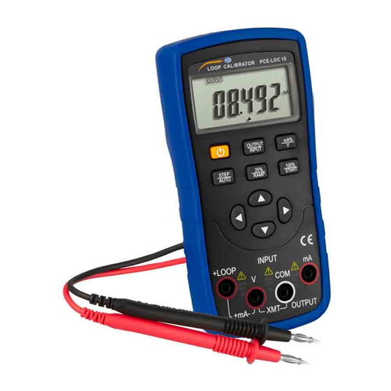
Device layout 1. LCD Display 6. 25% single step/Auto-ramp 2. Power 7. 0%-100% of setting/Auto-ramp start 3. Output/Input toggle 8. Output value set 4. mA% unit select 9. Input digit select 5. Single step/Auto toggle 10. Input/Output terminal © PCE Instruments... -
Page 6: Lcd Layout
Dirt or moisture in the terminals can affect the readings and should be avoided. Clean the terminals as follows: Turn the device off and remove all test leads. Shake out any dirt, accumulated in the terminals. Soak a cotton swab with alcohol and clean each terminal. © PCE Instruments... -
Page 7: Battery Replacement
Remove the device protector. • Remove the battery cover by unscrewing the screw with a screwdriver. • Replace with two new batteries; • Reinstall the battery case, tighten the screws and replace the device protector. Figure 3.1 Battery replacement © PCE Instruments... -
Page 8: Fuse Replacement
After turning the device on, an internal self-diagnosis procedure is carried out before the display is turned on. Note To prevent damage to the device, it is recommended to wait 5 seconds after turning the device off, before turning it on again. © PCE Instruments... -
Page 9: Automatic Power-Off
Use the ◄ or ► buttons to select the output digits. • Use the ▲ or ▼ buttons to change the value of the set digits. The value can be rounded or decremented automatically. Press and hold the button for one second to change the value continuously. © PCE Instruments... - Page 10 ▲, 0 and FS symbols will be displayed. Press the 100%/START button and the • Use the ▲ or ▼ buttons to change the output value from 100% (20mA) and 0% (4mA). • Press the 100%/START button again to exit the step current output. © PCE Instruments...
- Page 11 Figure 5.2 XMT output connection Note • Range of power supply: 5 to 25VDC • Connect a 24V DC power supply to the device while operating the current output, to prolong the working life of the battery. © PCE Instruments...
-
Page 12: Measurement Procedure
The device now begins to measure. ON and the measured result are now shown on the display. • The measurement refresh rate is twice per second. If the measured result exceeds the measuring range, OL will be shown on the display. INPUT +LOOP +mA- OUTPUT Figure 5.3 DC current measurement input © PCE Instruments... - Page 13 The device now begins to measure. ON and the measured result are now shown on the display. • The measurement refresh rate is twice per second. If the measured result exceeds the measuring range, OL will be shown on the display. INPUT +LOOP +mA- OUTPUT Figure 5.4 DC voltage measurement input © PCE Instruments...
-
Page 14: Performance Index
Input Range Resolution Accuracy Remark Range -0.200~ ±0.02% Input resistance Voltage about 1MΩ reading±2mV 28.000V -1.000~ ±0.02% resistance about Current 20mA 0.001mA 20Ω reading±4uA 22.000mA 0.000~ Loop ±0.02% providing 24V loop 20mA 0.001mA Current reading±4uA power 22.000mA © PCE Instruments... -
Page 15: Calibration
Calibration Each PCE-LOC 10 is delivered factory calibrated. To have the device recalibrated, please contact PCE Deutschland GmbH. Unintentional changes in the internal calibration menu can cause problems, e.g. inaccuracies. Warranty You can read our warranty terms in our General Business Terms which you can find here: https://www.pce-instruments.com/english/terms. - Page 16 PCE Instruments contact information Germany France Spain PCE Deutschland GmbH PCE Instruments France EURL PCE Ibérica S.L. Im Langel 4 23, rue de Strasbourg Calle Mayor, 53 D-59872 Meschede 67250 Soultz-Sous-Forets 02500 Tobarra (Albacete) Deutschland France España Tel.: +49 (0) 2903 976 99 0 Téléphone: +33 (0) 972 3537 17...
Need help?
Do you have a question about the PCE-LOC 10 and is the answer not in the manual?
Questions and answers