Table of Contents
Advertisement
Quick Links
Advertisement
Table of Contents

Related Manuals for PCE Instruments PCE-LES 400


Summary of Contents for PCE Instruments PCE-LES 400
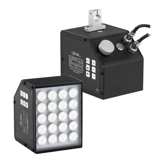
- Page 1 PCE-LES 400 FIXED LED STROBOSCOPE USER MANUAL...
-
Page 2: Preface
Fixed LED stroboscope PCE-LES 400 Preface Thank you so much for purchasing our products. To ensure optimal performance and safety, read the following instructions. Read this manual before operation. Wrong installation or use can lead to product damage or personal injury. - Page 3 Fixed LED stroboscope PCE-LES 400 Note: Please read the following notes carefully before use operate To avoid instrument failure, use it within the voltage range specified by the product. Strobe devices are non-explosion proof product, please do not use ...
-
Page 4: Table Of Contents
Fixed LED stroboscope PCE-LES 400 PREFACE ....................1 CHAPTER 1 THE STROBE INSTRUMENT FUNCTION ....4 AN OVERVIEW OF CHAPTER 2 ............5 2.1 O ..................5 VERVIEW 2.2 P ................5 RODUCT FEATURES 2.3 M ............5 AIN TECHNICAL INDICATORS CHAPTER 3 INTRODUCTION TO WORKING METHODS ..6 3.1 I... -
Page 5: Chapter 1 The Strobe Instrument Function
Fixed LED stroboscope PCE-LES 400 Chapter 1 The strobe instrument function The strobe is also called a strobe camera or tachometer, strobe light, etc. The strobe itself can emit a short and dense flash. Adjust the flash frequency of the strobe, make it with the rotation of the measured... -
Page 6: An Overview Of Chapter 2
Fixed LED stroboscope PCE-LES 400 An Overview of Chapter 2 2.1 Overview The fixed LED stroboscope PCE-LES 400 is a new generation of new energy strobe developed by our company. Internal high- performance microcomputer processing unit, efficient program processing, high precision strobe; LCD screen display data, convenient and intuitive interaction, efficient energy conversion chip, stable and reliable energy output;... -
Page 7: Chapter 3 Introduction To Working Methods
Fixed LED stroboscope PCE-LES 400 Frequency display: LCD display screen; Working mode: internal trigger and four external trigger modes; Strobe units are optional: f / m, Hz, m / min; Brightness adjustable: 3-1% flash period, maximum 100us. -
Page 8: Chapter Iv Operating Instructions
Fixed LED stroboscope PCE-LES 400 Delay-represents the angle of the delay, set to range from 0 to 359 degrees. Parameters of the perimeter standard length mode: perimeter C, standard length d C-represents the circumference,refers to the length corresponding to two consecutive signals, in mm, maximum 999.9mm; for example, a... -
Page 9: Start Up Or Stop The Flash
Fixed LED stroboscope PCE-LES 400 item up ▼ Number divided by 2; when parameter setting, select the menu item down Number plus one; hold this key for a long time Number minus one; hold this key for a long time... -
Page 10: Parameter Settings
Fixed LED stroboscope PCE-LES 400 4.4 Parameter settings Press SET to select the parameters to be set, press +, -, or turn the knob to modify the corresponding parameters or select the display unit. 4.5 Language settings Long press "SET 'key to enter the menu setting interface, press' ▲... - Page 11 Fixed LED stroboscope PCE-LES 400 ×1000 flashing rate : Trigger frequency in the strobe device, unit: time / minute; : Running speed of the machine in m / min. : The distance between two consecutive identical printing patterns, that is, the starting position of the first pattern to the starting position of the second pattern, in unit: mm;...
-
Page 12: Chapter V. Description Of The External Interface
Fixed LED stroboscope PCE-LES 400 Chapter V. Description of the external interface .15 External trigger wiring The external trigger interface pin is defined as follows: 1 foot —— + 12V —— strobe inside the DC12V ground 2 feet —— GND —— strobe internal DC12V power supply ... - Page 13 Fixed LED stroboscope PCE-LES 400 External power supply Encoder wiring method, connect to phase A or phase B. ...
-
Page 14: Chapter 6 Complete Set List
Fixed LED stroboscope PCE-LES 400 Chapter 6 Complete set list 1 x fixed LED stroboscope PCE-LES 400 1 x aluminium slot profile 1 x 4-pin coupling 1 x connection cable 1 x external trigger sensor 1 x fixing screws 1 x user manual... - Page 15 For countries outside the EU, batteries and devices should be disposed of in accordance with your local waste regulations. If you have any questions, please contact PCE Instruments. Chapter 8 PCE Instruments contact information...
Need help?
Do you have a question about the PCE-LES 400 and is the answer not in the manual?
Questions and answers