Advertisement
Quick Links
CLTI-2DIMU8/CLXI-2DIMU8
Terminal Block and Module
Installation Guide
Description
The Crestron
®
230 V, 2-Feed, 8-Dimmer Terminal Block and Module (CLTI-2DIMU8 and
CLXI-2DIMU8) are considered single entities and must be used together. They ship
separately to permit termination of the eld wiring to the terminal block (CLTI) prior to
installation of the module (CLXI). The terminal block is designed to terminate the circuit
feed (LINE and NEUTRAL) and distribute the controlled circuit (LOAD) to the xtures. The
module connects to the terminal block and performs dimming control of LED,
incandescent, magnetic low-voltage, or dimmable 2-wire uorescent lighting loads.
The maximum load is 2.5 A per channel; the maximum load is 20 A total for the
CLXI-2DIMU8. The CLXI-2DIMU8 accepts two 10 A feeds that can be different phases.
An oversize heat sink dissipates heat ef ciently. There are LEDs on the module to indicate
communication to a Cresnet
®
network, input power to the module, and output power to
the load.
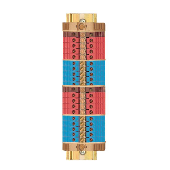
The CLTI terminals and CLXI modules are shown in the following illustrations.
CLTI-2DIMU8 Terminal Block with Left- and Right-Side CLXI-2DIMU8 Labels
CLX-2DIMU8
CLX-2DIMU8
2 FEED
2 FEED
8 DIM
8 DIM
120VAC 60 Hz
120VAC 60 Hz
SINGLE PHASE
SINGLE PHASE
16A MAX/FEED
16A MAX/FEED
LINE 1
N OUT 8
DIM 1
N OUT 7
DIM 2
N OUT 6
DIM 3
N OUT 5
DIM 4
N IN 2
N IN 1
DIM 8
N OUT 1
DIM 7
N OUT 2
DIM 6
N OUT 3
DIM 5
DIM 5
N OUT 4
LINE 2
LINE 2
N OUT 4
DIM 5
N OUT 3
DIM 6
N OUT 2
DIM 7
N OUT 1
DIM 8
N IN 1
N IN 2
DIM 4
N OUT 5
DIM 3
N OUT 6
DIM 2
N OUT 7
DIM 1
N OUT 8
LINE 1
CLXI-2DIMU8 Module (Connects to a CLTI-2DIMU8)
Speci cations
Speci cations are listed in the table below.
SPECIFICATION
DETAILS
Load Ratings
Dimmer Channels
8
Per Channel
2.5 A
Per Group
Channels 1–4: 10 A
Channels 5–8: 10 A
Module Total
20 A*
Minimum Load
0 A
Dimming Modes
Auto-load detection, forced reverse-phase, forced
forward-phase
Load Types
LED, incandescent, magnetic low-voltage, electronic
low-voltage, 2-wire uorescent and nondimmable
lighting
Power Requirements
One or two feeds (the same or different phases)
230 Vac, 50/60 Hz, single-phase
Environmental
Temperature
0° to 40 °C (32° to 104 °F)
Humidity
10% to 90% RH (noncondensing)
Heat Dissipation
12 Btu/h + (3.8 Btu/h x Load Current in A)
88 Btu/h at maximum load
Enclosure
Gray metal with black heat sink, surface mount
module with two integral mounting anges;
Occupies 1 module space in a CAEN or CAENIB
enclosure
Voltage Limit for
24 V
SELV/PELV Circuits
* When connecting to a third-party arc fault breaker, ensure that the total load does not exceed 1,000 W
per feed.
Additional Resources
Visit the product page on the Crestron website
(www.crestron.com) for additional information
and the latest rmware updates. Use a QR
reader application on your mobile device to
scan the QR image.
CLTI-2DIMU8
Installation
A licensed electrician must mount the terminal block and module into a Crestron
Automation Enclosure in accordance with all national and local codes.
CAUTION: This equipment is for indoor use only and needs to be air cooled. Mount in a
well-ventilated area. The ambient temperature must be 10° to 40 °C (32° to 104 °F). The
relative humidity must be 10% to 90% (noncondensing).
NOTE: For 2-feed systems, the two input lines can be different phases.
NOTE: When connecting to an arc fault breaker, ensure the load does not exceed
1,000 W total. Crestron certi ed breakers have a 2,000 W limit.
IMPORTANT NOTES: When controlling magnetic low-voltage transformers:
• Do not use a CLXI-2DIMU8 module for switching or dimming large magnetic
transformers (>100 VA).
• Do not connect more than eight magnetic transformers on any one output, regardless
of lamp wattage.
• Do not hot plug transformers or add or remove bypass jumpers while the output
channel is energized.
• Do not mix magnetic and electronic transformers on the same output channel.
Failure to follow the guidelines above can lead to damage of the dimmer module and
transformers.
NOTE: Before using the CLXI-2DIMU8, ensure the device is using the latest rmware.
Check for the latest rmware for the CLXI-2DIMU8 at www.crestron.com/ rmware. Load
the rmware onto the device using Crestron Toolbox™ software.
Install terminal blocks along the left side of single-wide enclosures and along the outside
edges (left and right sides) of double-wide enclosures. Install modules along the right side
of single-wide enclosures and side-by-side in the center of double-wide enclosures. When
installing modules and terminal blocks in a double-wide enclosure, be sure to invert the
units on the right side so that they can be properly wired. Refer to the illustrations that
follow when considering the location of terminal blocks and modules within an enclosure.
NOTE: Modules and terminal blocks must be installed into the lowest available spaces
and continue toward the top of the enclosure.
Terminal Block and Module Layout for a Single-Wide Enclosure (CLTI-2DIMU8 and
CLXI-2DIMU8 Shown)
Ground bus
CLTI- terminal
CLXI- module
block
CLXI-2DIMU8
Terminal Block and Module Layout for a Double-Wide Enclosure (CLTI-2DIMU8 and
CLXI-2DIMU8 Shown)
CLTI- terminal block
CLXI- module
Ground bus
NOTE: Unless otherwise indicated, the lighting system speci ed in this guide is
modular, requiring assembly in the eld by a licensed electrician in accordance with all
national and local codes.
If an assembled UL
Listed panel is required, Crestron offers this service through its UL
®
Listed panel shop. This includes complete in-factory system con guration and assembly
by Crestron for an additional fee.
Terminal Block Installation and Field Wiring
Terminal block installation requires installation of the supplied adhesive label and the
terminal block. The adhesive label provides the labeling for each terminal in the terminal
block and is designed to accommodate installation into the left or right side of a cabinet.
Refer to the illustrations that follow for details.
WARNING: The CLXI-2DIMU8 may be powered from multiple circuit breakers.
NOTE: Both left-side and right-side adhesive wiring labels are provided. The left-side
labels are used in both single- and double-wide enclosures. The right-side labels are
used only in double-wide enclosures.
1. Remove the backing from the left- or right-side adhesive wiring label.
2. Apply the adhesive label by aligning the holes in the label with the holes on the
Crestron Automation Enclosure where the terminal block is to be mounted. The
wiring label lies beneath the terminal block.
3. Use the two supplied self-tapping Phillips pan head screws (8B x 1/4 in length) to
secure the terminal block to the Crestron Automation Enclosure.
CAUTION: Bypass jumpers are provided to allow testing of circuits and to protect
the module during installation. When properly secured by ve screws, each of the
two jumpers on the brown and red sections of the terminal block shorts the line in
to dim out so that the circuit is energized. Do not remove any bypass jumpers until
all feed and load wiring has been completed, the circuit has been tested for
electrical faults, and the module has been installed. Refer to "Module Installation
and Wiring" for details.
Furthermore, the two jumpers on the blue sections of the terminal block tie the
neutral ins to the neutral outs. These jumpers should never be removed.
NOTE: Use copper conductors only—rated 75 °C or greater.
4. Turn off the circuit breakers.
5. Connect the circuit feed (line and neutral) and controlled circuit (load) wires to the
terminal block per the markings provided on the wiring label. Terminal blocks accept
one 2.5–6 mm
2
wire. Strip the wires to 12 mm (1/2 in). Tighten terminal blocks to
1 Nm.
6. Grounding terminal blocks are available in the cabinet for termination of ground
wires. Tighten to 4 Nm (2.5–6 mm
2
7. Test each circuit for electrical faults by turning on each of the circuit breakers and
checking that the breakers do not trip and that power is delivered to the proper
loads.
Wiring the Terminal Block to the Feed and Load(s) (Single-Wide and Left-Side Double-Wide
Enclosures)
LINE 1
Connection from a
15 or 20 A circuit
breaker
NEUTRAL
CLTI- terminal block
LINE 2
Connection from a
15 or 20 A circuit
breaker
CLX-2DIMU8
2 FEED
8 DIM
120VAC 60 Hz
SINGLE PHASE
16A MAX/FEED
N OUT 8
N OUT 7
N OUT 6
NEUTRAL
N OUT 5
N IN 2
DIM 8
DIM 7
GND
DIM 6
DIM 5
DIM 5
LINE 2
N OUT 4
N OUT 3
N OUT 2
N OUT 1
N IN 1
DIM 4
DIM 3
To loads
DIM 2
DIM 1
LINE 1
Module
Ground
location
bus
label
), 4.5 Nm (10 mm
2
), or 5.1 Nm (16–25 mm
2
).
CLX-2DIMU8
2 FEED
8 DIM
120VAC 60 Hz
SINGLE PHASE
16A MAX/FEED
LINE 1
DIM 1
DIM 2
DIM 3
DIM 4
N IN 1
N OUT 1
N OUT 2
N OUT 3
N OUT 4
LINE 2
DIM 5
DIM 6
DIM 7
DIM 8
N IN 2
N OUT 5
N OUT 6
N OUT 7
N OUT 8
Bypass
jumpers
Left-side
Terminal
wiring label
block
Advertisement

Related Manuals for Crestron CLTI-2DIMU8


Summary of Contents for Crestron CLTI-2DIMU8
- Page 1 230 V, 2-Feed, 8-Dimmer Terminal Block and Module (CLTI-2DIMU8 and Speci cations are listed in the table below. A licensed electrician must mount the terminal block and module into a Crestron CLXI-2DIMU8) are considered single entities and must be used together. They ship Automation Enclosure in accordance with all national and local codes.
- Page 2 Forward Phase mode. As of the date of manufacture, these products have been tested and found to comply with Crestron disclaims any proprietary interest in the marks and names of others. Crestron is not responsible speci cations for CE marking.