Table of Contents
Advertisement
-----------
-------------
OWNER'S MANUAL
WARRANTY CARD
SPARE PARTS CATALOGUE
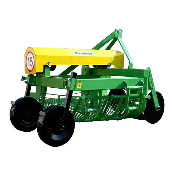
1-ROW VIBRATING DIGGER
Ursa
Z655 - VIBRATING DIGGER
WITH SIDE DISCHARGE
Z655/1 - VIBRATING DIGGER
WITH REAR DISCHARGE
PRIOR TO STARTING WORK, PLEASE READ THIS
OPERATING INSTRUCTIONS
®
BOMET
Spółka z ograniczoną odpowiedzialnością
Spółka Komandytowa
07-100 Węgrów, ul. B. Joselewicza 2
tel. (0 prefix 25) 691 78 06
Edition 2, Węgrów 2017 Eng
Original manual
Advertisement
Table of Contents

Related Manuals for Bomet Z655/1

Summary of Contents for Bomet Z655/1
- Page 1 OWNER'S MANUAL WARRANTY CARD SPARE PARTS CATALOGUE 1-ROW VIBRATING DIGGER Ursa Z655 - VIBRATING DIGGER WITH SIDE DISCHARGE Z655/1 - VIBRATING DIGGER WITH REAR DISCHARGE PRIOR TO STARTING WORK, PLEASE READ THIS OPERATING INSTRUCTIONS ® BOMET Spółka z ograniczoną odpowiedzialnością...
- Page 3 Spółka Komandytowa 07-100 Węgrów, ul. B. Joselewicza 2 tel. (0 prefix 25) 691 78 06 http:www.bomet.pl; e-mail: bomet@bomet.pl DECLARATION OF CONFORMITY for a machine According to the Ordinance of Minister of Economy of 21 October 2008 (Journal of Laws "Dziennik Ustaw" No 199, item 1228) and European Union Directive 2006/42/WE of 17 May 2006 Official Journal of the European Union L157 p.
- Page 4 - 2 -...
- Page 5 Spółka Komandytowa 07-100 Węgrów, ul. B. Joselewicza 2 tel. (0 prefix 25) 691 78 06 http:www.bomet.pl; e-mail: bomet@bomet.pl DECLARATION OF CONFORMITY for a machine According to the Ordinance of Minister of Economy of 21 October 2008 (Journal of Laws "Dziennik Ustaw" No 199, item 1228) and European Union Directive 2006/42/WE of 17 May 2006 Official Journal of the European Union L157 p.
-
Page 6: W A R R A N T Y C A R D
W A R R A N T Y C A R D 1-row vibrating digger type Z655 Serial number ..........201 ..Production date Inspector signature ..........Date of sale ..........Seller signature ..................Seller stamp CAUTION: It is seller’s obligation to fill in the warranty card and complaint forms carefully (legibly). - Page 7 Complaint form no 1 1-row vibrating digger type Z655 Serial number ..........Date of sale ..........Seller’s signature and stamp Complaint protocol number ......Complaint form no 2 1-row vibrating digger type Z655 Serial number ..........Date of sale ..........Seller’s signature and stamp Complaint protocol number ......
- Page 8 After repair I received technically efficient machine on ..........…………………………………………………….. User’s signature Notices: ........................................................................After repair I received technically efficient machine on ..........…………………………………………………….. User’s signature Notices: ........................................................................After repair I received technically efficient machine on ..........……………………………………………………..
- Page 9 IDENTIFICATION 1-ROW VIBRATING DIGGER 1-row vibrating digger type Z655 has a rating plate, fitted in the front part of the digger frame. Basic data which serves for identification of the machine: manufacturer’s name, machine symbol, serial number, year of production, is put there. Data placed on the rating plate serves for identification of the digger and ought to correspond to the following data, filled in during the sales.
-
Page 10: Table Of Contents
TABLE OF CONTENTS W A R R A N T Y C A R D ......................... 4 1. INTRODUCTION ..........................9 2. INTENDED USE OF THE DIGGER ....................9 3. SAFETY PRECAUTIONS AND WARNINGS ................10 3.1. Symbols: meaning and application ................... 10 3.2. -
Page 11: Introduction
Digger submerges in the ridge with a ploughshare taking soil along with potatoes and then the soil is sifted on two hoppers while potatoes are put on the left side in a narrow strip in the distance enabling another working passage. Vibrating digger of Z655/1 series puts potatoes behind the digger. -
Page 12: Safety Precautions And Warnings
3. SAFETY PRECAUTIONS AND WARNINGS 3.1. Symbols: meaning and application In the present manual symbols are used in order to draw the reader’s attention and stress certain particularly important aspects requiring discussion. DANGER This indicates danger, with a possible serious accident risk. Not obeying recommendations marked with this sign may cause a situation of a serious risk of sustaining an injury by the operator and/or people nearby! Obey strictly these recommendations! -
Page 13: Estimation Of Residual Risk
Maintenance and adjustment at the digger when the tractor engine is working and the machine is not protected against falling down. When describing residual risk of the digger, the digger is treated as a machine, which since the moment of starting the production, has been designed and manufactured according to the present technique condition. -
Page 14: General Regulations
3.5.1. General regulations Apart from this manual, one shall also follow traffic regulations and occupational safety and health regulations. Warnings (pictograms) placed on the digger give advice concerning safety of the user and other people, and avoiding accidents. ... -
Page 15: Transportation Of The Machine
When removing clogs, if necessary, use special tools and secure the raised digger against falling down with a support e.g. a wood block. It is not allowed to use tractor reverse gear during work, when the machine is in the working position. -
Page 16: Standard Conformity
3.6. Standard conformity The machine has been designed and made in accordance with standards concerning safety in the machine industry, valid on the day of marketing the digger. Particularly, following legal acts and harmonized standards have been taken into account: ... -
Page 17: Noise And Vibrations
Table 1. Safety signs and captions Pictogram Meaning Location Rating plate At the front of the frame on the left (Rating plate) side Caution. Before operating the At the front, on the rack of the machine, read the manual. three-point suspension system Caution. -
Page 18: Usage Regulations
There is no threat caused by vibrations when working with a digger because the operator’s workplace is located in the tractor cabin where the seat is amortized and properly ergonomically shaped. 4. USAGE REGULATIONS 4.1. General information Vibrating digger Z655 is manufactured as a 1-row machine suspended on tractor three-point suspension system. -
Page 19: Construction Of The Vibrating Digger With Rear Discharge
variable adjustment of ploughing. At the back of the digger frame there are also brackets for installing portable warning devices (11) and a triangular sign for low-speed vehicles. 4.2.2 Construction of the vibrating digger with rear discharge Vibrating digger with rear discharge (Figure 2) can be employed on light and medium compacted soils, not too stony, weedy and with fragmented haulms. -
Page 20: Preparing The Digger To Work
aggregate the digger with recommended tractor classes equipped with standard ballasts of front axle and rear wheels in accordance with data given in the technical characteristics of the tractor. Air pressure, particularly in rear tires of the tractor should be equal in both wheels and in accordance with the tractor’s manual! Before suspension of the machine, lower rods of the tractor’s suspension system shall be set in lower position at the same height (distance between joints and the ground is... -
Page 21: Adjustment And Setting Of The Digger
CAUTION It is forbidden to connect the machine with a tractor when the tractor engine is running. It is forbidden to use other elements to secure the tool suspension system than recommended by the manufacturer. CAUTION Pay particular attention when aggregating the digger, do not keep place between the digger and the tractor. -
Page 22: Technical Operation
of the digger should be installed in the brackets so that the right wheel does not press a neighboring ridge. WARNING All clogging made during work of the digger requiring interference in the operation, shall be removed after stopping the tractor, lowering the digger onto the ground or support, turning off the tractor engine and pulling the handbrake. -
Page 23: Digger Storage
tightened. Loss occurred in paint coat should be cleaned and filled by covering with a fresh layer of protective paint and then the digger shall be greased in accordance with the lubrication instruction (see point 5.6). 5.3. Digger storage Digger should be kept under a roof on the flat, solid ground. In case of lack of a roofed place, it is possible to keep the machine outside. -
Page 24: Lubrication Instruction
5.5. Lubrication instruction Basic maintenance activities are keeping lubrication periods and using proper types of grease. Before lubrication all the points of lubrication shall be cleaned out of contamination. Lubrication of the digger shall be performed according to the table 3. Table 2. -
Page 25: Transportation Of A Digger On The Tractor Three-Point Suspension System
CAUTION When loading the diggers on means of transport, lines or chains shall be installed in places marked by the manufacturer with pictograms. 6.2. Transportation of a digger on the tractor three-point suspension system Digger is adjusted for transportation on public roads on the tractor three-point suspension system. -
Page 26: Technical Characteristics
material type. Uninstalled elements should be grouped and passed to points collecting metals. CAUTION Lifting devices used during disassembly can be operated only by a person properly authorized and qualified. 8. TECHNICAL CHARACTERISTICS Technical data of suspended 1-row vibrating digger is listed in table 4. Table. -
Page 27: Spare Parts Catalogue
SPARE PARTS CATALOGUE How to use the catalogue. Spare parts catalogue includes other assemblies of the 1-row vibrating digger marked with proper numbers. The catalogue should be used as follows: - determine the proper assembly the exchanged part belongs to according to the tables, - find the needed part on the assembly table following the reference number from the assembly drawing. - Page 28 - 26 -...
- Page 29 Table 1. Vibrating digger with side discharge Position Number of items Part name KTM symbol picture or norm number Z655 Frame set 5655 - 01 - 001 Suspension system studs 5655 - 01 - 002 Ploughshare bracket L* 5655 - 02 - 001 Ploughshare bracket R* 5655 - 02 - 002 Topper ploughshare L*...
- Page 30 - 28 -...
- Page 31 Table 2. Vibrating digger with rear discharge Poz. Liczba sztuk Nazwa części Symbol KTM rysunku lub numer normy Z655/1 Frame set 6551 - 02 - 01 Support wheel set L 6551 - 02 - 02 Support wheel set R 6551 - 02 - 03...
Need help?
Do you have a question about the Z655/1 and is the answer not in the manual?
Questions and answers