
Related Manuals for YASKAWA CM092


Summary of Contents for YASKAWA CM092
- Page 1 EtherNet/IP™ Option CM092 Technical Manual Document Number: TM.AFD.26 Models: CIMR-F7U, CIMR-G7U, CIMR-P7U, CIMR-E7U, CIMR-G5M(Spec F), CIMR-G5M(600V), G5HHP...
- Page 2 Any warnings provided by YASKAWA must be promptly provided to the end user. YASKAWA offers an express warranty only as to the quality of its products in conforming to standards and specifications published in the YASKAWA manual.
-
Page 3: Introduction
Introduction This manual explains the specifications and handling of the Yaskawa EtherNet/IP Option Card for the Yaskawa F7U, G7U, P7U, E7U, GPD515/G5M (F Spec), GPD515/G5 (600V) and G5HHP drives. The EtherNet/IP Option Card connects the drive to an EtherNet/IP network and facilitates the exchange of data. In this document, the word "inverter", "AC drive" and "drive" may be used interchangeably. -
Page 4: Table Of Contents
Chapter 3 EtherNet/IP Objects ................... 3-1 Supported Output Instances ................3-2 Yaskawa Output Instances.................. 3-4 Supported Input Instances................... 3-6 Yaskawa Input Instances..................3-8 CIP Supported Objects..................3-12 Yaskawa Supported Objects ................3-19 Fault Code Conversions..................3-23 Chapter 4 Product Specification.................. 4-1 Product Specification ..................4-2... - Page 5 Firmware Description ..................4-2 Chapter 5 Parameter Tables..................5-1 Class/Instance/Attribute Tables ................5-2 Hexadecimal/Decimal Conversion ..............5-22...
-
Page 6: Chapter 1 Installation
Chapter 1 Installation This section describes how to install and set up the EtherNet/IP Option Card. Installation Check Sheet ..................1-2 Unpack and Inspect..................... 1-3 Install the EtherNet/IP Option Card..............1-5 EtherNet/IP Option Card..................1-7 Network and Web Access Configuration ............1-10 Important Notes .................... -
Page 7: Installation Check Sheet
Installation Check Sheet The following is a quick reference checklist to install and configure the EtherNet/IP Option Card. Make a copy of this page and check-off each item as it is completed. For detailed information please refer to the detailed sections that follow. Unpack the EtherNet/IP Option Card and verify that all components are present and undamaged. -
Page 8: Unpack And Inspect
Unpack the EtherNet/IP Option kit and verify that all components are present and undamaged. Ground Wire Shielded RJ-45 M-F Cable Fig 1.1 – CM092 Option Kit Table 1.1 – CM092 Option Kit Contents CM092 EtherNet/IP Option Kit Parts Qty. EtherNet/IP Option Card... - Page 9 Verify Drive Operation Connect power to the Yaskawa AC drive and verify that the drive functions correctly. This includes running the drive from the operator keypad. Refer to the appropriate drive technical manual for information on connecting and operating the drive.
-
Page 10: Install The Ethernet/Ip Option Card
Install the EtherNet/IP Option Card Remove the Operator Keypad and Drive Cover Remove the operator keypad. Remove the terminal and control covers. Remove the option card hold-down by carefully compressing the top and bottom until it becomes free of its holder. Lift it out. Installation 1-5... - Page 11 Route the RJ-45 M-F cable and the ground wire along the left-inside of the AC drive enclosure. Replace the option card hold-down. Connect the ground wire from the option card terminal J6 to the terminal assembly ground connection. Fig 1.2 – Install the CM092 on an F7U Drive Installation 1-6...
-
Page 12: Ethernet/Ip Option Card
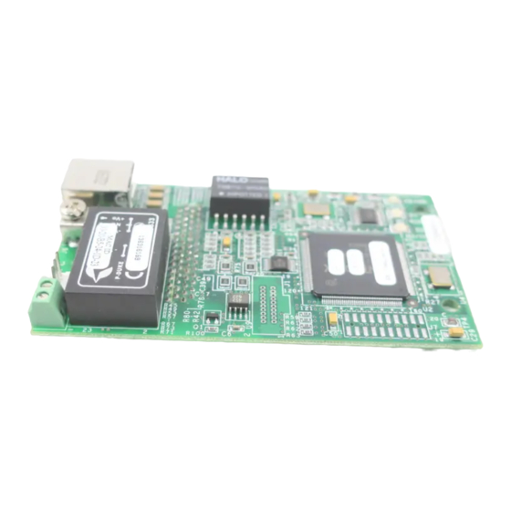
EtherNet/IP Option Card Fig 1.3 – CM092 Option Card Details Diagnostic LED Power-up Sequence A power-up test is performed each time the AC drive is powered-up after the initial boot-up sequence. The initial boot-up sequence may take several seconds. When this sequence is complete, the LEDs will assume their normal conditions. - Page 13 LED Description Table 1.3 – LED States Label Description GREEN – Card Functioning Normally REEN BLINK – Standby/Initializing (500ms cycle) MS/RUN RED BLINK – Minor Fault (500ms cycle) RED – Major Fault GREEN/RED BLINK – Module Test (500ms cycle) GREEN – Connected GREEN BLINK –...
- Page 14 EtherNet/IP Option Card LED States Table 1.4 - EtherNet/IP Option Card LED States Indicator Behavior Description Steady No Power No power is applied to the option card the LED remains OFF. Green Normal Operation The option card is operating correctly with all initialization checks complete. Steady Green Standby / Initializing...
-
Page 15: Network And Web Access Configuration
DHCP Server connected to the network in order to have the IP address of the EtherNet/IP Option Card set. For detailed information on how to setup the Rockwell BOOTP/DHCP Server on a PC refer to the appropriate Rockwell document or Yaskawa's Application Note AN.AFD.10. - Page 16 Obtain the IP address of the desired drive and enter that IP address in the browser address bar. Hit Enter. The IP address of the desired drive is 192.168.1.20 in this example. The main web page should be displayed. Fig 1.4 – CM092 Main Web Page Installation 1-11...
- Page 17 Configuring a PC with a Static IP Address Select an existing connection or create a new network connection for communication with the EtherNet/IP Option Card. Select Start ==> Settings ==> Network Connections from the task bar in the Windows OS. Select the network connection to be used.
- Page 18 Note: The IP address in the browser address bar will have to be changed to the drive's new IP address and the web page refreshed in order to continue to communicate with the EtherNet/IP Option Card web pages. Fig 1.6 – CM092 Option Web Configuration Installation 1-13...
-
Page 19: Important Notes
Fig 1.7 – Placing the MAC ID Label To simplify the drive configuration, obtain EDS files at www.yaskawa.com. From the Yaskawa web site, select Downloads => By Inverter Drives => By Product => Network Comms-Ethernet. Then select the appropriate EDS file based on drive series and the lat- est version of those listed. -
Page 20: Resetting The Ethernet/Ip Option Card To Its Default
192.168.1.1 Symptom: The Yaskawa EtherNet/IP Option Card main web page does not display on the PC web browser screen. Corrective Action: Check that the PC is setup, properly connected and that an IP address has been assigned to both the server and the node and that they are on the same local network. -
Page 21: Drive Fault Messages
Drive Fault Messages The table of EtherNet/IP Option Card fault codes returned by the drive is shown below. Refer to the appropriate drive user and/or programming manual(s) for drive specific information on the fault returned. Table 1.5 – Fault Code Conversions Drive Fault EtherNet/IP Drive Fault... - Page 22 Drive Fault Operator Messages The following is a table of faults that could be caused by the EtherNet/IP Option Card that will be displayed on the Operator Keypad only. For any fault displayed on the operator that is not listed in the following table, please see the appropriate drive technical manual. Table 1.6 –...
- Page 23 Notes Installation 1-18...
-
Page 24: Chapter 2 Browser Interface
Chapter 2 Browser Interface This section describes the web server or browser interface to the EtherNet/IP Option Card. Main Web Page....................2-2 Configuration Web Page..................2-3 Submit Page ......................2-4 Network Diagnostics Web Page ................. 2-5 Drive Diagnostics Web Page ................2-6 Browser Interface 2-1... -
Page 25: Main Web Page
Speed: Connection Speed: Current connection speed. Either 10 or 100 will be displayed. IP Address: The IP address of the current EtherNet/IP Option Card. Standard Footer The standard footer contains information on how to contact Yaskawa for technical support. Browser Interface 2-2... -
Page 26: Configuration Web Page
Configuration Web Page The configuration page contains the standard header and footer along with a method of configuring the EtherNet/IP server and web server interfaces of the EtherNet/IP Option Card. Fig 2.2 – Configuration Web Page Web Server Configuration The web server configuration allows for the setting of the IP Address, Subnet Mask, Gateway and EtherNet/IP server type. All octets must contain valid numbers between 0 and 255. -
Page 27: Submit Page
Submit Page After any of the configuration parameters shown above have been changed, the submit button must be pressed to store the changed data. The drive must then be power cycled for the new data to take affect. Verify that the data on the submit page is correct. Fig 2.3 –... -
Page 28: Network Diagnostics Web Page
Network Diagnostics Web Page The network diagnostics page displays the standard header and footer along with information relative to network and EtherNet/IP Option Card performance. Fig 2.4 – Network Diagnostics Web Page Message Tx OK: Transmit Message Count: The number of messages sent from the EtherNet/IP Option Card. Message Rx OK: Receive Message Count: The number of messages received by the EtherNet/IP Option Card. -
Page 29: Drive Diagnostics Web Page
Drive Diagnostics Web Page The drive diagnostics page contains the standard header and footer along with diagnostic information specific to the current drive. Fig 2.5 – Drive Diagnostics Web Page Freq Ref: Frequency Reference – Monitor Parameter U1-01. Motor Speed: Motor Speed –... -
Page 30: Chapter 3 Ethernet/Ip Objects
In the following tables G5M represents the G5M (F Spec), G5(600V) and G5M(HHP ) drives. Supported Output Instances ................3-2 Yaskawa Output Instances.................. 3-4 Supported Input Instances................... 3-6 Yaskawa Input Instances..................3-8 CIP Supported Objects..................3-12 Yaskawa Supported Objects ................3-19 Fault Code Conversions..................3-23 EtherNet/IP 3-1... -
Page 31: Supported Output Instances
Supported Output Instances Basic Speed Control Output Instance 20 (14h) Output Byte Bit 7 Bit 6 Bit 5 Bit 4 Bit 3 Bit 2 Bit 1 Bit 0 Fault Instance Reset Forward Speed Reference (Low Byte) [scaled by parameter o1-03] Speed Reference (High Byte) [scaled by parameter o1-03] Run Forward: Forward RUN Command... - Page 32 Speed and Torque Control Output Instance 22 (16h) Output Byte Bit 7 Bit 6 Bit 5 Bit 4 Bit 3 Bit 2 Bit 1 Bit 0 Fault Instance Reset Forward Speed Reference (Low Byte) [scaled by parameter o1-03] Speed Reference (High Byte) [scaled by parameter o1-03] Torque Reference (Low Byte) [0.1%]...
-
Page 33: Yaskawa Output Instances
Yaskawa Output Instances Yaskawa Standard Speed/Torque Control Output Instance 101 (65h) Output Byte Bit 7 Bit 6 Bit 5 Bit 4 Bit 3 Bit 2 Bit 1 Bit 0 Terminal Terminal Terminal Terminal Terminal Terminal Reverse Forward Instance Terminal Terminal... - Page 34 Yaskawa Extended Speed/Torque Control Output Instance 115 (73h) Output Byte Bit 7 Bit 6 Bit 5 Bit 4 Bit 3 Bit 2 Bit 1 Bit 0 Terminal Terminal Terminal Terminal Terminal Terminal Reverse Forward Instance Terminal Terminal Terminal Fault External...
-
Page 35: Supported Input Instances
Supported Input Instances Basic Speed Control Input Instance 70 (46h) Input Byte Bit 7 Bit 6 Bit 5 Bit 4 Bit 3 Bit 2 Bit 1 Bit 0 Running 1 Instance Faulted (FWD) Speed Actual (Low Byte) [scaled by parameter o1-03] Speed Actual (High Byte) [scaled by parameter o1-03] Faulted: Drive Fault... - Page 36 Speed and Torque Control Input Instance 72 (48h) Input Byte Bit 7 Bit 6 Bit 5 Bit 4 Bit 3 Bit 2 Bit 1 Bit 0 Running 1 Instance Faulted (FWD) Speed Actual (Low Byte) [scaled by parameter o1-03 Speed Actual (High Byte) [scaled by parameter o1-03] Torque Actual (Low Byte) [0.1%] Torque Actual...
-
Page 37: Yaskawa Input Instances
Yaskawa Input Instances Yaskawa Standard Speed/Torque Input Instance 151 (97h) Input Byte Bit 7 Bit 6 Bit 5 Bit 4 Bit 3 Bit 2 Bit 1 Bit 0 Speed Running Running FAULT ALARM READY Reset Agree Instance Terminal Terminal Terminal... - Page 38 Yaskawa Extended Speed/Torque Input Instance 155 (9Bh) Input Byte Bit 7 Bit 6 Bit 5 Bit 4 Bit 3 Bit 2 Bit 1 Bit 0 Speed FAULT ALARM READY Reset Agree Running Running Instance Terminal Terminal Terminal Local/ M1-M2 Remote...
- Page 39 OPE: Drive OPE Fault Drive Undervoltage Fault Local/Remote: 0 = Drive is in Local Control 1 = Drive is in Remote Control Terminal M1-M2: Multi-function Digital Output 1 (H2-01) Terminal P1: Multi-function Digital Output 2 (H2-02) Terminal P2: Multi-function Digital Output 3 (H2-03) (F7U and G7U only) ZSV: Zero Servo (F7U, G7U and G5M in Closed-loop flux vector mode (FVC)
- Page 40 Yaskawa Extended Speed/Torque Input Instance 155 (9Bh) (Details for bytes 10 through 23, Error Alarm Signals 1, 2, and 3) Bytes 18 (Low) and 19 (High) - Bytes 20 (Low) and 21 (High) - Bytes 22 (Low) and 23 (High) -...
-
Page 41: Cip Supported Objects
Size Default Value Object Software Revision Word Maximum Instances Word Vendor ID Word 44 (YASKAWA) Device Type Word 2 (AC drives) Product/Model Dependant Code- For factory use. Product Code Word Refer to Attribute 7-Product Name, for drive family and model. - Page 42 Class 04h – Assembly Object Service Code No. (hex) Service Name Get Attribute Single Set Attribute Single Attributes Instance ID Attribute Description Size Default Value Object Software Revision Word 20 (14h) Data Array 4 Bytes 00 00 00 00 21 (15h) Data Array 4 Bytes 00 00 00 00...
- Page 43 Class F5h – TCP/IP Object Service Code No. (hex) Service Name Get Attribute All Get Attribute Single Set Attribute Single Attributes Instance ID Attribute Description Size Default Value Object Software Revision Word Maximum Instance Word Bit 0: Not configured Status Long Bit 1: Configured Bit 2~31: Reserved...
- Page 44 Class F6h - Ethernet Link Object Service Code No. (hex) Service Name Get Attribute All Get Attribute Single Set Attribute Single Get and Clear Attributes Instance ID Attribute Description Size Default Value Object Software Revision Word Maximum Instance Word Interface Speed Long Bit 0: Link Status Bit 1: 0: Half Duplex...
- Page 45 Class 29h – Control Supervisor Object Service Code No. (hex) Service Name Get Attribute Single Set Attribute Single RESET Attributes Instance ID Attribute Description Size V7 Data Object Software Revision Word Run 1 (Forward Run) Byte Forward Run Command Run 2 (Reverse Run) Byte Reverse Run Command Net Control...
- Page 46 Class 2Ah – AC Drive Object Service Code No. (hex) Service Name Get Attribute Single Set Attribute Single Attributes Instance ID Attribute Description Size F7U/G7U/P7U/E7U/G5M Data Object Software Revision Word At Reference Byte Speed Agree Net Reference Byte Net Reference Command - Parameter b1-01 Drive Mode Byte Control Method - Parameter A1-02...
- Page 47 Class 28h – Motor Object Service Code No. (hex) Service Name Get Attribute Single Set Attribute Single Attributes Instance ID Attribute Description Size F7U/G7U/P7U/E7U/G5M Data Object Software Revision Word Motor 1 Type Byte 7 (0 ~ 10) EtherNet/IP 3-18...
-
Page 48: Yaskawa Supported Objects
255 (FFh) Enter Command (FFFDh) Word Yaskawa Command Object – Class 64h, Instance 1, Attribute 1 – Operation Command Definition Forward RUN (1) /Stop (0) Bits 1 and 2 may not be set simultaneously Reverse RUN (1) /Stop (0) Bits 1 and 2 may not be set simultaneously Terminal S3 –... - Page 49 Yaskawa Command Object – Class 64h, Instance 1, Attribute 8 – Digital Output Definition PHC 1 – Multi-function Digital Output 1 – Parameter H2-01 setting* PHC 2 – Multi-function Digital Output 2 – Parameter H2-02 setting* Reserved Reserved Reserved Reserved Fault Contact Enable Fault Contact –...
- Page 50 Class 65, Instance 1, Attribute 1, Drive Status Attribute 1 - Drive Status Word Status Drive Running Zero Speed Reverse Running Reset Command Received Speed Agree Inverter Ready Alarm Condition Fault Condition Not Used Momentary Power Loss Ride Thru Local / Remote Digital Output 1 Digital Output 2 Digital Output 3 (F7U/G7U Only)
- Page 51 Class 65 – Yaskawa Status Object (continued) Attribute 10 - Fault Code Word 1 Attribute 11 - Fault Code Word 2 Attribute 12 - Fault Code Word 3 Fault Fault Fault PUF DC Bus Fuse Open EF3 External Fault - Terminal S3...
-
Page 52: Fault Code Conversions
Fault Code Conversions Table 1.7 – Drive Fault Messages (by EtherNet/IP Communication) EtherNet/IP Drive Fault EtherNet/IP Drive Fault Fault Code Code Description Fault Code Code Description [hex] [hex] [hex] [hex] 0000h None 6320h EEPROM R/W Error (ERR) 2120h Ground Fault (GF) 7110h Dynamic Braking Transistor (RR) 2130h... - Page 53 Notes EtherNet/IP 3-24...
-
Page 54: Chapter 4 Product Specification
Chapter 4 Product Specification This section describes the specification for the EtherNet/IP Option Card. Product Specification ..................4-2 Firmware Description ..................4-2 Product Specification 4-1... -
Page 55: Product Specification
The following Status Assembly information is available in the EtherNet/IP interface, which is implemented as the normal heartbeat information in CIP. The following states of the device along with the additional flags provide for monitoring the EtherNet/IP enabled Yaskawa drives. Value... - Page 56 Connections The maximum number of simultaneous connections is: 1 for I/O, 4 for Explicit, 2 for Drive Wizard™. Cable Loss and Timeout Timeout is calculated based on RPI configuration parameter on startup. It is specified in seconds. A setting of "0" disables the timeout. The default cable loss timeout is RPI* 4.
- Page 57 Notes Product Specification 4-4...
-
Page 58: Chapter 5 Parameter Tables
Chapter 5 Parameter Tables Class/Instance/Attribute Tables ................5-2 Hexadecimal/Decimal Conversion ..............5-22 Product Codes & Parameter Tables 5-1... -
Page 59: Class/Instance/Attribute Tables
Class/Instance/Attribute Tables The following tables list all the drive monitors and parameters that are supported by the EtherNet/IP Option Card. Each drive has its own set of Classes (CLASS), Instances (INST), and Attributes (ATTR) for each monitor and parameter, so be sure to reference the proper column for the drive. - Page 60 Attribute [hex] Monitor Name U1-30 MWh Monitor kWh 94 (5Eh) 94 (5Eh) 94 (5Eh) 94 (5Eh) U1-32 ACR (q) Output % 96 (60h) 96 (60h) 62 (3Eh) U1-33 ACR (d) Output % 97 (61h) 97 (61h) 63 (3Fh) U1-34 OPE Detected 98 (62h) 98 (62h) 98 (62h)
- Page 61 Class 73h, Instance 1 - Fault Monitors/G5M CASE Monitors* U1-50 ~ U1-59* *CASE Monitors are only used in custom drive software. Monitor parameters all share the same service (GET), data type (Word) and number of bytes (2) Attribute [hex] Monitor Name U2-01 Current Fault...
- Page 62 Class 74h, Instance 1 - Extended Fault History Monitor parameters all share the same service (GET), data type (Word) and number of bytes (2) Attribute [hex] Monitor Name U3-09 Fault Message 5 U3-10 Fault Message 6 U3-11 Fault Message 7 U3-12 Fault Message 8 U3-13...
- Page 63 Class 67h, Instance 1 - Initialize/User Object AX-XX parameters all share the same service (GET/SET), data type (Word) and number of bytes (2) Attribute [hex] Parameter Name A1-00 Selection Language A1-01 Access Level A1-02 Control Method A1-03 Initialize Parameters A1-04 Enter Password A1-05 Selection Password...
- Page 64 Class 68h, Instance 1 - Application Object bX-XX parameters all share the same service (GET/SET), data type (Word) and number of bytes (2) Attribute [hex] Parameter Name b1-01 Reference Source b1-02 Run Source b1-03 Stopping Method b1-04 Reverse Operation b1-05 Zero Speed Operation b1-06 Control Input Scans...
- Page 65 Class 68h, Instance 1 - Application Object (continued) bX-XX parameters all share the same service (GET/SET), data type (Word) and number of bytes (2) Attribute [hex] Parameter Name b5-18 PID Set Point Selection 93 (5Dh) 93 (5Dh) 93 (5Dh) 93 (5Dh) b5-19 PID Set Point 94 (5Eh)
- Page 66 Class 69h, Instance 1 - Tuning Object CX-XX parameters all share the same service (GET/SET), data type (Word) and number of bytes (2) Attribute [hex] Parameter Name C1-01 Accel Time 1 Sec C1-02 Decel Time 1 Sec C1-03 Accel Time 2 Sec C1-04 Decel Time 2 Sec C1-05...
- Page 67 Class 69h, Instance 1 - Tuning Object (Continued) Attribute [hex] Parameter Name C8-09 AFR Time 44 (2Ch) C8-30 Carrier During Rotational Auto-tune 65 (41h) C9-04 CT/VT Selection 76 (4Ch) C6-02 in G5M C6-03 in G5M Class 6Ah, Instance 1 - Reference Object dX-XX parameters all share the same service (GET/SET), data type (Word) and number of bytes (2) Attribute [hex] Parameter...
- Page 68 Class 6Ah, Instance 1 - Reference Object (Continued) Attribute [hex] Parameter Name d5-05 Speed Limit Bias % 31 (1Fh) 31 (1Fh) 22 (16h) d5-06 Reference Hold Time mS 32 (20h) 32 (20h) 23 (17h) d5-07 Rotational Direction 39 (27h) d6-01 Magnetic Weakening Field 33 (22h) 33 (22h)
- Page 69 Class 6Bh, Instance 1 - Motor Object (Continued) Attribute [hex] Parameter Name E3-03 Motor 2 Maximum Voltage VAC 28 (1Ch) 28 (1Ch) E3-04 Motor 2 Base Frequency Hz 29 (1Dh) 29 (1Dh) E3-05 Motor 2 Mid Frequency Hz 30 (1Eh) 30 (1Eh) E3-06 Motor 2 Mid Voltage VAC...
- Page 70 Class 6Ch, Instance 1 - Option Object (Continued) Attribute [hex] Parameter Name F1-14 PGO Detection Time Sec 14 (0Eh) 14 (0Eh) 24 (18h) F1-21 PG Pulses/Revolution 2 49 (31h) F1-22 PG Rotation Selection 2 50 (32h) F1-23 PG Gear Teeth 1 51 (33h) F1-24 PG Gear Teeth 2...
- Page 71 Class 6Dh, Instance 1 - Terminal Object HX-XX parameters all share the same service (GET/SET), data type (Word) and number of bytes (2) Attribute [hex] Parameter Name H1-01 Terminal S3 Function Selection H1-02 Terminal S4 Function Selection H1-03 Terminal S5 Function Selection H1-04 Terminal S6 Function Selection H1-05...
- Page 72 Class 6Dh, Instance 1 - Terminal Object (Continued) Attribute [hex] Parameter Name H5-08 Communication Protocol Selection 53 (35h) H5-09 Communication Error Detection Time 54 (36h) 54 (346) H6-01 Pulse Input Selection 45 (2Dh) 45 (2Dh) H6-02 Pulse Input Selection 46 (2Eh) 46 (2Eh) H6-03 Pulse Input Scaling Hz...
- Page 73 Class 6Eh, Instance 1 - Protection Object (Continued) Attribute [hex] Parameter Name L5-01 Number Of Restarts 31 (1Fh) 31 (1Fh) 31 (1Fh) 31 (1Fh) 22 (16h) L5-02 Restart Selection 32 (20h) 32 (20h) 32 (20h) 32 (20h) 23 (17h) L5-03 Maximum Restart Time 33 (21h) 33 (21h)
- Page 74 Class 6Fh, Instance 1 - Operator Object OX-XX parameters all share the same service (GET/SET), data type (Word) and number of bytes (2) Attribute [hex] Parameter Name o1-01 User Monitor Selection o1-02 Power On Monitor o1-03 Display Scaling o1-04 Display Units o1-05 Address Display o1-06...
- Page 75 Class 70h, Instance 1 - G5M CASE Object* *CASE Parameters are only used in custom drive software. PX-XX parameters all share the same service (GET/SET), data type (Word) and number of bytes (2) Attribute [hex] Parameter Name P1-01 Case Parameter 1 P1-02 Case Parameter 2 P1-03...
- Page 76 Class 70h, Instance 1 - Factory Adjustment Object NX-XX parameters all share the same service (GET/SET), data type (Word) and number of bytes (2) Attribute [hex] Parameter Name N1-01 Hunting Prevention Selection N1-02 Hunting Prevention Gain N2-01 AFR Gain N2-02 AFR Time mS N2-03 AFR Time 2 mS...
- Page 77 Class 71h, Instance 1 - 7-Series CASE Parameter Object* *CASE Parameters are only used in custom drive software. PX-XX parameters all share the same service (GET/SET), data type (Word) and number of bytes (2) Attribute [hex] Parameter Name P1-01 Case Parameter 1 P1-02 Case Parameter 2 P1-03...
- Page 78 Class 72h, Instance 1, Auto-tune Object TX-XX parameters all share the same service (GET/SET), data type (Word) and number of bytes (2) Attribute [hex] Parameter Name T1-00 Motor Selection T1-01 Tuning Mode Selection T1-02 Motor Rated Power kW T1-03 Motor Rated Voltage VAC T1-04 Rated Current A T1-05...
-
Page 79: Hexadecimal/Decimal Conversion
Hexadecimal/Decimal Conversion Table B.1 – Hexadecimal/Decimal Conversions Decimal Decimal Decimal Decimal Decimal Product Codes & Parameter Tables 5-22... - Page 80 Table B.1 – Hexadecimal/Decimal Conversions Decimal Decimal Decimal Decimal Decimal Product Codes & Parameter Tables 5-23...
- Page 81 Notes Product Codes & Parameter Tables 5-24...
- Page 82 New Pier Takeshiba South Tower, 1-16-1, Kaigan, Minatoku, Tokyo, 105-0022, Japan Phone: 81-3-5402-4511 Fax: 81-3-5402-4580 Internet: http://www.yaskawa.co.jp YASKAWA ELECTRIC EUROPE GmbH Hauptstraße 185,65760 Eschborn, Germany Phone: 49-6196-569-300 Fax: 49-6196-569-398 YEA Document Number: TM.AFD.26 04/08/2010 Rev: 10-04 Data subject to change without notice. Yaskawa Electric America, Inc.
Need help?
Do you have a question about the CM092 and is the answer not in the manual?
Questions and answers