
Subscribe to Our Youtube Channel
Related Manuals for SMA Solar Technology SUNNY CENTRAL 630CP-JP


Summary of Contents for SMA Solar Technology SUNNY CENTRAL 630CP-JP
- Page 1 User Manual SUNNY CENTRAL 500CP-JP / 630CP-JP / 800CP-JP / 1000CP-JP U T I L I G R A ENGLISH SCCP-JP-B1-BA-en-23 | 98-103200.07 | Version 2.3...
- Page 2 The information contained in these documents is the property of SMA Solar Technology AG. Any publication, whether in whole or in part, requires prior written approval by SMA Solar Technology AG. Internal reproduction used solely for the purpose of product evaluation or other proper use is allowed and does not require prior approval.
-
Page 3: Table Of Contents
SMA Solar Technology AG Table of Contents Table of Contents Information on this Document..................... Validity ................................Target Group ..............................Additional Information............................. Levels of warning messages..........................Symbols in the Document..........................10 Typographies ..............................10 Designations in the Document ........................10 Safety ............................11 Intended Use.............................. - Page 4 Table of Contents SMA Solar Technology AG Function Test..............................33 4.5.1 Checking the Fans............................33 4.5.2 Checking the Heating Elements and Hygrostat ..................... 34 Configuration ..............................35 4.6.1 Configuring the Network Settings on the Computer..................35 4.6.2 Information on Integrating the Inverter into a Local Network ............... 35 4.6.3...
- Page 5 SMA Solar Technology AG Table of Contents 4.6.15.2 Starting the automatic capture of the accepted IP addresses..............49 4.6.15.3 Entering accepted IP addresses via the user interface ................. 49 4.6.16 Resetting the Communication Unit ........................50 Switching the Inverter On..........................50 Disconnecting and Reconnecting ....................
- Page 6 Table of Contents SMA Solar Technology AG Troubleshooting..........................64 Safety during Troubleshooting........................64 Activating Alert under Fault Conditions......................65 Reading Off Disturbance Messages ......................65 7.3.1 Reading Off Error Messages via Touch Display.................... 65 7.3.2 Reading Off Disturbance Messages via the User Interface ................65 7.3.3...
- Page 7 SMA Solar Technology AG Table of Contents 10.2.2 Automatic Shutdown Functions ........................87 10.2.2.1 Grid Management Shutdown ........................87 10.2.2.2 Transformer Protection ............................ 87 10.2.2.3 Active Islanding Detection..........................87 10.2.2.4 Passive Islanding Detection ..........................88 10.2.2.5 Behavior in Case of Increasing Temperatures ....................88 10.2.3...
- Page 8 Table of Contents SMA Solar Technology AG 11 Operating Data and Parameters....................115 11.1 Operating Data ............................... 115 11.1.1 Inverter ................................115 11.1.1.1 Power Limitation .............................. 115 11.1.1.2 Error Channels..............................117 11.1.1.3 Measured Values............................117 11.1.1.4 Internal Device Values ............................ 117 11.1.1.5 Internal Meters ..............................118 11.1.1.6 Service-Relevant Displays ..........................
-
Page 9: Information On This Document
SMA Solar Technology AG 1 Information on this Document 1 Information on this Document Validity This document is valid for the following device types: Device type Production version OCU firmware DSP firmware version version SC 500CP‑10‑JP (Sunny Central 500CP‑JP) 02.00.01.R 02.00.01.R SC 630CP‑10‑JP (Sunny Central 630CP‑JP) 02.00.01.R... -
Page 10: Symbols In The Document
1 Information on this Document SMA Solar Technology AG NOTICE Indicates a situation which, if not avoided, can result in property damage. Symbols in the Document Symbol Explanation Information that is important for a specific topic or goal, but is not safety-relevant Indicates a requirement for meeting a specific goal ☐... -
Page 11: Safety
Alterations to the product, e.g. changes or modifications, are only permitted with the express written permission of SMA Solar Technology AG. Unauthorized alterations will void guarantee and warranty claims and in most cases terminate the operating license. SMA Solar Technology AG shall not be held liable for any damage caused by such changes. -
Page 12: Safety Information
2 Safety SMA Solar Technology AG Safety Information This section contains safety information that must be observed at all times when working on or with the product. To prevent personal injury and property damage and to ensure long-term operation of the product, read this section carefully and observe all safety information at all times. - Page 13 SMA Solar Technology AG 2 Safety DANGER Danger to life from electric shock even if the inverter is disconnected on the AC and DC sides The precharge unit of the order option "Q at Night" will carry live voltage even if the AC contactor and the DC switchgear are open.
- Page 14 2 Safety SMA Solar Technology AG WARNING Danger to life due to blocked escape routes In hazardous situations, blocked escape routes can lead to death or serious injury. Opening the doors of two products located opposite each other can block the escape route. It is imperative that the escape route is freely accessible at all times.
-
Page 15: Cyber Security
Internet. You can find the current recommendations by SMA Solar Technology AG on the topic Cyber Security in the Technical Information "PUBLIC CYBER SECURITY - Guidelines for a Secure PV System Communication" at www.SMA-Solar.com. -
Page 16: Product Overview
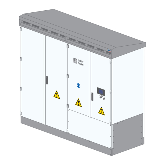
3 Product Overview SMA Solar Technology AG 3 Product Overview Design of the Inverter Figure 1: Design of the Inverter Position Designation Inverter cabinet Interface cabinet Connection area Devices of the Inverter Figure 2: Inverter Components Position Component Description Touch Display Different kinds of inverter data can be viewed on the touch display. -
Page 17: Operating And Display Elements
SMA Solar Technology AG 3 Product Overview Position Component Description SC-COM The SC-COM is the communication unit of the inverter. The SC-COM estab- lishes the connection between the inverter and the system operator. AC disconnection unit With the AC disconnection unit, the electrical connection between the in- verter and MV transformer can be disconnected manually. -
Page 18: Ac Disconnection Unit
3 Product Overview SMA Solar Technology AG 3.3.1.2 AC Disconnection Unit The AC disconnection unit disconnects the inverter from the MV transformer. Figure 4: Switch positions of the AC disconnection unit from ABB Position Designation Explanation Switch position on The AC disconnection unit is closed. -
Page 19: Touch Display
SMA Solar Technology AG 3 Product Overview Position Designation ON button OFF button 3.3.2 Touch Display 3.3.2.1 Design The touch display is used to display instantaneous values and parameter settings. Tapping the symbols on the touch display activates the corresponding functions. If the touch display has not been touched for five minutes, the display is locked and the logged-in user will be logged out. - Page 20 3 Product Overview SMA Solar Technology AG Symbol Designation Explanation DC side Representation of the instantaneous values • PV power in W • Insulation resistance in Ω • PV current in A • PV voltage in V • Diagram of string-current monitoring –...
- Page 21 SMA Solar Technology AG 3 Product Overview Symbol Designation Explanation AC side Representation of the following instantaneous values: • Active power in W • Reactive power in VAr • Power frequency in Hz • AC current in A • AC voltage in V...
- Page 22 3 Product Overview SMA Solar Technology AG Symbol Designation Explanation Settings • Language selection • Brightness setting • Time setting • Format selection • Password entry Information • OS: version of the operating system • App.: version of the application software •...
-
Page 23: Leds Of The Sc-Com
SMA Solar Technology AG 3 Product Overview 3.3.3 LEDs of the SC-COM 3.3.3.1 LEDs on the Enclosure Figure 7: LEDs on the enclosure LED designation Status Explanation POWER glowing green The SC-COM is supplied with voltage. The SC-COM is not supplied with voltage. -
Page 24: Leds On The Network Port
3 Product Overview SMA Solar Technology AG LED designation Status Explanation flashing green The SC-COM is communicating with the devices connected within the system. glowing green Internal communication has taken place in the last five minutes. glowing red An error has occurred in the internal communication. -
Page 25: Leds On The Optical Fiber Terminals
SMA Solar Technology AG 3 Product Overview 3.3.3.3 LEDs on the Optical Fiber Terminals The SC-COM is also available with pre-wired optical fiber connections. If the optical fibers are connected to the splice box of the inverter, the status of the connection will be indicated by the LEDs of the SC-COM. -
Page 26: User Interface
3 Product Overview SMA Solar Technology AG 3.3.4 User Interface 3.3.4.1 Design of the User Interface Via the user interface, you can set the communication of the devices of your PV power plant, configure the inverter parameters and read off error messages and operating data. -
Page 27: Status Symbols
SMA Solar Technology AG 3 Product Overview 3.3.4.3 Status Symbols Depending on the status of the device communication, the device symbols are displayed in the tree or device view with various status symbols. Symbol Explanation The inverter is ready for operation. -
Page 28: Commissioning
4 Commissioning SMA Solar Technology AG 4 Commissioning Safety during Commissioning DANGER Danger to life from electric shock due to live voltage High voltages are present in the live components of the product. Touching live components results in death or serious injury due to electric shock. -
Page 29: Requirements For Commissioning
SMA Solar Technology AG 4 Commissioning Requirements for Commissioning ☐ None of the devices must display any damage. ☐ All devices must be correctly installed. ☐ All devices must be properly grounded. ☐ All transport locks and desiccant bags must be removed. -
Page 30: Checking The High-Current Contacts Made At The Installation Site
4 Commissioning SMA Solar Technology AG Test Point Tasks Cable support rails Ensure that the cables are adequately attached to the cable support rails. Shield clamping sad- Ensure that the contact between the cable shield and the shield bus is intact. -
Page 31: Checking The Connectors
SMA Solar Technology AG 4 Commissioning 4.3.6 Checking the Connectors Test Point Tasks Connectors on the CAN bus Ensure that all connectors are securely in place. Connectors on the SC20cont Connectors on the inverter bridge Connectors on the communication unit... -
Page 32: Checking The Dc Voltage
4 Commissioning SMA Solar Technology AG 4.4.3 Checking the DC Voltage DANGER Danger to life due to electric arcs if measuring device is not connected correctly If the measurement points are incorrectly contacted, this can cause an electric arc. Electric arcs can result in death or serious injury. -
Page 33: Function Test
SMA Solar Technology AG 4 Commissioning 2. Switch on the circuit breaker of the grid monitoring. 3. Switch on the AC circuit breaker. 4. Switch the supply voltage circuit breaker on. ☑ The electronic components of the inverter switch on. -
Page 34: Checking The Heating Elements And Hygrostat
4 Commissioning SMA Solar Technology AG 4.5.2 Checking the Heating Elements and Hygrostat Figure 11: Position of the heating element and the hygrostat Position Designation Hygrostat Heating element DANGER Danger to life due to electric shock or electric arc if live components are touched •... -
Page 35: Configuration
SMA Solar Technology AG 4 Commissioning 4. Check whether the heating elements are radiating heat after a delay time of five minutes. If the heating elements are not radiating heat, contact us (see Section 13 "Contact", page 149). 5. Reset the hygrostat to the initial value. To do this, press the selector switch back towards the hygrostat. The initial value of the hygrostat is indicated on the hygrostat. -
Page 36: Adjusting Network Ports
4 Commissioning SMA Solar Technology AG Procedure: 1. Log into the user interface (see Section 9.4.1, page 80). 2. Select Sunny Central > Settings > Network. 3. In the field IP address, enter the static IP address that you want to use to access the inverter in the local network. -
Page 37: Detecting New Devices
SMA Solar Technology AG 4 Commissioning 4.6.5 Detecting New Devices During commissioning of a PV power plant, all devices must be detected. If multiple interfaces (e.g. COM2 and COM3) are used in the inverter, detection of new devices must be carried out separately for all interfaces. -
Page 38: Setting The Frequency-Independent Active Power Limitation
4 Commissioning SMA Solar Technology AG 4. Change the parameters P-HzStr, P-HzStop and P-WGra and save (see Section 9.3.2, page 80). 5. Save the parameter changes (see Section 9.3.2, page 80). 4.6.6.3 Setting the Frequency-Independent Active Power Limitation NOTICE Operation failure of the PV power plant due to incorrectly set parameters If the parameter settings for grid management services are incorrect, the PV power plant may not be able to meet the requirements of the grid operator. -
Page 39: Setting Q At Night
SMA Solar Technology AG 4 Commissioning Avoiding electromagnetic interference emissions in large-scale PV systems To avoid electromagnetic interference emissions in large-scale PV systems at the changeover from night mode to feed-in operation, it is recommended using Modbus communication for setpoint in feed-in operation and night mode. -
Page 40: Setting Grid Monitoring And Grid Limits
4 Commissioning SMA Solar Technology AG Procedure: 1. Make sure the inverter is in the operating state "Stop". 2. Call up the parameter overview (see Section 9.3.1, page 80). 3. Set the parameter QoDQ-VarMod to the desired value. 4. Change the parameters belonging to the selected mode (see Section 10.3.4, page 102). -
Page 41: Setting The Grid Support
SMA Solar Technology AG 4 Commissioning Manual Resume Mode after Parameter Disconnection due to overfrequency ManResOvrFrq Disconnection due to underfrequency ManResUndrFrq Disconnection due to passive islanding detection ManResPID Disconnection due to disturbance in a line conductor ManResPLD 3. Save the parameter changes (see Section 9.3.2, page 80). -
Page 42: Deactivating The "Fully Hermetic" Transformer Protection
4 Commissioning SMA Solar Technology AG 3. To deactivate remote shutdown, set the parameter ExlStrStpEna to Off (see Section 10.2.1.2, page 87). 4. Save the parameter changes (see Section 9.3.2, page 80). 4.6.9.2 Deactivating the "Fully Hermetic" Transformer Protection 1. Call up the parameter overview (see Section 9.3.1, page 80). -
Page 43: Redetecting The Sunny String-Monitors Via The Sunny Central String-Monitor Controller
SMA Solar Technology AG 4 Commissioning 4.6.10.4 Redetecting the Sunny String-Monitors via the Sunny Central String- Monitor Controller 1. Log into the user interface (see Section 9.4.1, page 80). 2. Select the tab Parameters. 3. Set the parameter DevFunc to Retry. 4. Select the button [Save]. -
Page 44: Assigning Strings To Different Measuring Channels
4 Commissioning SMA Solar Technology AG Setting the monitoring period for all Sunny String-Monitors 1. Log into the user interface (see Section 9.4.1, page 80). 2. Select the parameter MoniTmGrAllOn and set the start of the monitoring period. 3. Select the parameter MoniTmGrAllOff and set the end of the monitoring period. -
Page 45: Setting The Tolerance
SMA Solar Technology AG 4 Commissioning Procedure: 1. Select the desired Sunny Central String-Monitor Controller from the device list. 2. Select the tab Parameters. 3. Enter the tripping time in minutes in the parameter field SMU_T_Ausl. 4. Select the button [Save]. 4.6.10.12 Setting the Tolerance You can use the tolerance to set the sensitivity of the string-current monitoring. -
Page 46: Selecting The Display Format
4 Commissioning SMA Solar Technology AG Procedure: 1. Select 2. Select 3. To change the date, select the day, month and year in the field . Use the buttons to change the day, month and year. 4. To change the time, select the hours, minutes and seconds in the field . -
Page 47: Entering The Operator Name
SMA Solar Technology AG 4 Commissioning 5. Select an option in the Automatic change from summer time to winter time field: Option Explanation Automatic change from daylight saving time to standard time is active. Automatic change from daylight saving time to standard time is not active. Date and time have to be set manually. -
Page 48: Configuring System Settings Via Xml File
4 Commissioning SMA Solar Technology AG 4.6.14 Configuring System Settings via XML File 4.6.14.1 Uploading the File custom.xml When you upload the file custom.xml to the user interface, the communication unit checks the file to ensure that the values entered are valid and accurate, and adopts the settings at the next reset of the communication unit. -
Page 49: Deleting The File Custom.xml
SMA Solar Technology AG 4 Commissioning 4.6.14.3 Deleting the File custom.xml You can delete the file custom.xml via the user interface. If you have enabled your personal settings via the file custom.xml before deleting it, these settings will remain effective. -
Page 50: Resetting The Communication Unit
4 Commissioning SMA Solar Technology AG 4.6.16 Resetting the Communication Unit Resetting the communication unit will restore all of its original default settings. If you have uploaded an XML file custom.xml, the settings of this file will be adopted (see Section 4.6.14.1 "Uploading the File custom.xml", page 48). -
Page 51: Disconnecting And Reconnecting
SMA Solar Technology AG 5 Disconnecting and Reconnecting 5 Disconnecting and Reconnecting Safety When Disconnecting and Reconnecting Voltage Sources DANGER Danger to life from electric shock due to live voltage High voltages are present in the live components of the product. Touching live components results in death or serious injury due to electric shock. -
Page 52: Disconnecting The Ac Side
5 Disconnecting and Reconnecting SMA Solar Technology AG 5.2.3 Disconnecting the AC Side 1. Switch off the inverter (see Section 5.2.1, page 51). 2. Disconnect the DC side (see Section 5.2.2, page 51). 3. Externally disconnect the AC voltage of the MV transformer. 4. Switch off the AC disconnection unit in the inverter. -
Page 53: Reconnecting The Inverter
SMA Solar Technology AG 5 Disconnecting and Reconnecting 6. Ensure that no voltage is present. 7. Cover or isolate any adjacent live components. Reconnecting the Inverter 5.3.1 Reconnecting the Supply Voltage at the Inverter 1. Close the measurement and disconnect terminals. -
Page 54: Reconnecting The Dc Side
5 Disconnecting and Reconnecting SMA Solar Technology AG 5.3.3 Reconnecting the DC Side 1. Insert all fuses and disconnection blades into all fuse holders of the inverter. Use an LV/HRC fuse extractor. 2. Screw on the protective covers over the fuses (torque: 5 Nm). -
Page 55: Operation
SMA Solar Technology AG 6 Operation 6 Operation Safety during Operation NOTICE Operation failure of the PV power plant due to incorrectly set parameters If the parameter settings for grid management services are incorrect, the PV power plant may not be able to meet the requirements of the grid operator. -
Page 56: Adjusting The Pv System Identifier For Sunny Portal
6 Operation SMA Solar Technology AG 8. Select the button [Save]. 9. Select Sunny Central > Info. 10. Select [Register] in the field Last Sunny Portal registration. The Sunny Portal password will be sent to the e- mail address you have entered. -
Page 57: Downloading Operating Data Using The Ftp Server
SMA Solar Technology AG 6 Operation If the data transmission to Sunny Portal or the external FTP server fails, the communication unit will make further attempts to transmit the data. Procedure: 1. Log into the user interface (see Section 9.4.1, page 80). 2. Select Sunny Central > Settings > Data transmission. -
Page 58: Activating Automatic Data Transmission Via Ftp Push
6 Operation SMA Solar Technology AG 6.3.3.3 Activating Automatic Data Transmission via FTP Push The communication unit is equipped with an FTP push function. With this function, the data collected from your PV power plant can be uploaded as an XML file to a local FTP server. -
Page 59: Downloading Data In Csv Format
SMA Solar Technology AG 6 Operation 6.3.4.2 Downloading Data in CSV Format Data saved in CSV format can be automatically imported into tables (e.g. in Microsoft Excel). The configured separator and end of line characters are used to structure the data. -
Page 60: Saving Operating Data On A Memory Card
6 Operation SMA Solar Technology AG 6.3.5 Saving Operating Data on a Memory Card 6.3.5.1 Information on Saving Data on a Memory Card You can save all the data collected from the inverter to a memory card. The save-to-memory-card feature is disabled by default. -
Page 61: Displaying The Memory Capacity Available On The Memory Card
SMA Solar Technology AG 6 Operation 6.3.5.4 Displaying the Memory Capacity Available on the Memory Card 1. Log into the user interface (see Section 9.4.1, page 80). 2. Select Sunny Central > Info. 3. In the field Sunny Portal Buffer Load, you can see the space available in the internal ring buffer. -
Page 62: Switching To Insulated Operation
6 Operation SMA Solar Technology AG The order option "GFDI and insulation monitoring device" allows you to manually switch the PV power plant from grounded operation to insulated operation. To ensure that there is no insulation error on the grounded terminal, an insulation measurement is carried out. -
Page 63: Switching To Insulated Operation
SMA Solar Technology AG 6 Operation 6.5.2.2 Switching to Insulated Operation 1. Log into the user interface (see Section 9.4.1, page 80). 2. Set the parameter RemMntSvc to On. ☑ The insulation monitoring device starts collecting data. If the parameter IsoErrIgn is set to On, the error 3504 - Insulation failure ignored is displayed. -
Page 64: Troubleshooting
7 Troubleshooting SMA Solar Technology AG 7 Troubleshooting Safety during Troubleshooting DANGER Danger to life from electric shock due to high voltages on the product High voltages can be present on the product under fault conditions. Touching live components results in death or serious injury due to electric shock. -
Page 65: Activating Alert Under Fault Conditions
SMA Solar Technology AG 7 Troubleshooting Activating Alert under Fault Conditions You can be notified by e-mail of events that have occurred. This allows a rapid response to failures in the PV power plant and minimizes downtimes. The alert is deactivated upon delivery. -
Page 66: Displaying The Event Report
7 Troubleshooting SMA Solar Technology AG 4. To display the error message, select the instantaneous value Msg in the instantaneous value view. 5. To display the corrective measure, select the instantaneous value Dsc in the instantaneous value view. 7.3.3 Displaying the Event Report 7.3.3.1... -
Page 67: Remedial Action In Case Of Disturbances
SMA Solar Technology AG 7 Troubleshooting Procedure: 1. If an insulation error has occurred, switch the insulation monitoring device back on. 2. Log into the user interface (see Section 9.4.1, page 80). 3. Select the parameter Ackn in the device displaying the error, and set to Ackn. -
Page 68: Explanation Of The Error Tables
7 Troubleshooting SMA Solar Technology AG • System-specific The inverter switches to the operating state "Disturbance" and opens the AC contactor and DC switchgear. The inverter does not feed in. How long the inverter remains in this state depends on the system-specific influencing factors. -
Page 69: Error Numbers 01Xx To 13Xx - Disturbance On The Utility Grid
SMA Solar Technology AG 7 Troubleshooting 7.5.3 Error Numbers 01xx to 13xx - Disturbance on the Utility Grid After a grid failure, the inverter monitors the utility grid for a specific period before reconnecting. When the inverter monitors the utility grid after a grid error, the grid monitoring time is complied with. Certain errors, such as grid errors, cause the inverter to shut down. -
Page 70: Error Numbers 34Xx To 40Xx - Disturbance On The Pv Array
7 Troubleshooting SMA Solar Technology AG Error no. Explanation Inverter behavior Corrective measures 0801* One line conductor of the utility 30 s 30 s ‒ • Check the grid voltage. grid has failed. • Make sure the external fuses work 0802* properly. -
Page 71: Error Numbers 6Xxx To 9Xxx - Disturbance On The Inverter
SMA Solar Technology AG 7 Troubleshooting Error no. Explanation Inverter behavior Corrective measures 3515 A ground fault detected by ‒ • Check the PV array for ground faults. Soft Grounding has been ignored. 3517 Insulation measuring is being per- ‒ ‒... - Page 72 7 Troubleshooting SMA Solar Technology AG Error no. Explanation Inverter behavior Corrective measures 6120 Watchdog tripping error 30 s ‒ • Contact the SMA Service Line. 6121 No response from watchdog 30 s ‒ • Contact the SMA Service Line. 6122 Ten internal monitoring errors have 5 min ‒...
- Page 73 SMA Solar Technology AG 7 Troubleshooting Error no. Explanation Inverter behavior Corrective measures 6454 AC current is faulty. ‒ • Contact the SMA Service Line. 6455 AC voltage is faulty. ‒ • Contact the SMA Service Line. 6456 Pre-charging circuit of DC link is ‒...
- Page 74 7 Troubleshooting SMA Solar Technology AG Error no. Explanation Inverter behavior Corrective measures 7501 Interior fan is defective. ‒ • Check function of the fans. • Clean the fans. 7502 ‒ • Clean clogged fan inlets and ventilation 7503 Inverter bridge fan is defective.
-
Page 75: Displaying Disturbance Messages For Active Power Limitation
SMA Solar Technology AG 7 Troubleshooting Error no. Explanation Inverter behavior Corrective measures 8701 External active power setpoints ‒ • Contact the SMA Service Line. are smaller than 2 mA and there- fore invalid. The last valid value or, after a day change, Pmax is used. -
Page 76: Displaying Disturbance Messages For The Reactive Power Setpoint
7 Troubleshooting SMA Solar Technology AG Display Cause and corrective measures AnInFail The mode WCnstNomAnIn has been selected and the value measured at the analog in- put is less than 2 mA. Corrective measures: • Make sure the cable is correctly connected to the analog input. -
Page 77: Disposal
SMA Solar Technology AG 8 Disposal 8 Disposal Proper disassembly and disposal When the inverter has reached the end of its service life, it becomes electronic waste. Electronic waste contains on the one hand valuable materials which can be recycled as secondary raw materials, and on the other, substances which are hazardous to the environment. -
Page 78: Periodic Actions
9 Periodic Actions SMA Solar Technology AG 9 Periodic Actions Mounting and Disassembly Work 9.1.1 Disassembling and Mounting the Panels DANGER Danger to life due to electric shock or electric arc if live components are touched • Switch off the inverter and wait at least 15 minutes before opening it to allow the capacitors to discharge completely. -
Page 79: Disassembling And Mounting The Protective Covers
SMA Solar Technology AG 9 Periodic Actions 9.1.2 Disassembling and Mounting the Protective Covers Figure 12: Position of the protective covers Position Designation Protective cover DANGER Danger to life due to electric shock or electric arc if live components are touched •... -
Page 80: Entering The Password Via The Touch Display
9 Periodic Actions SMA Solar Technology AG Entering the Password via the Touch Display Installer access The "Installer" access level is activated by entering the installer password. The access level is reset after 15 minutes. Procedure: 1. Select 2. Select 3. -
Page 81: Logging Out Of The User Interface
SMA Solar Technology AG 9 Periodic Actions Requirement: ☐ JavaScript must be enabled in your web browser (e.g. Internet Explorer). Procedure: 1. Connect the laptop to the service interface of the inverter. 2. Start your web browser. 3. Enter the IP address of the communication unit in the address bar and press the enter key. -
Page 82: Function Description
10 Function Description SMA Solar Technology AG 10 Function Description 10.1 Operating States 10.1.1 Overview of the Operating States Figure 13: General overview of the operating states of the inverter 10.1.2 Stop The inverter is switched off. Stop, Fast stop or Remote shutdown active will appear on the touch display. If the key switch is set to Start, the inverter switches to the operating state "Grid monitoring". -
Page 83: Grid Monitoring
SMA Solar Technology AG 10 Function Description 10.1.3 Grid Monitoring 10.1.3.1 Monitoring the Grid Voltage In the operating state "Grid monitoring", Waiting for valid AC grid appears on the touch display. The grid limits are monitored continuously from now on. If no grid error occurs during the grid monitoring time, the AC contactor closes and the inverter switches to the operating state "Grid monitoring time reached". -
Page 84: Monitoring The Power Frequency
10 Function Description SMA Solar Technology AG Position Parameter Description ‒ Grid limit level 2 is breached for delay time level 2 → grid disconnec- tion ‒ Grid limit level 1 is breached for delay time level 1 → grid disconnec- tion (has already occurred on level 2) ‒... -
Page 85: Startup
SMA Solar Technology AG 10 Function Description 10.1.5 Startup 10.1.5.1 In Normal Operation: Active Power Ramp-Up The inverter works up to its maximum feed-in power via a ramp. This means that the inverter gradually increases the ratio of feed-in power per second by the value set in the parameter WGra. -
Page 86: Shutdown
10 Function Description SMA Solar Technology AG If the AC power generated by the inverter falls below 5 kW, the inverter switches from feed-in operation to "Q at Night" operation. The inverter feeds in reactive power in accordance with the parameter settings. Since this status can also occur during the day, the DC switchgear remains closed at first in order to avoid unnecessary switching cycles of the DC switchgear. -
Page 87: Remote Shutdown
SMA Solar Technology AG 10 Function Description The external fast stop must be connected in accordance with the circuit diagram. The external fast-stop function must be connected via a shielded cable. Tripping the fast stop The fast stop should only be tripped in case of imminent danger. Tripping of the fast stop does not entail fast discharge of the capacitors. -
Page 88: Passive Islanding Detection
10 Function Description SMA Solar Technology AG 10.2.2.4 Passive Islanding Detection The inverter is equipped with passive islanding detection. This function can be activated if required. The islanding detection function detects the formation of stand-alone grids and disconnects the inverter from the utility grid. -
Page 89: Ground-Fault Monitoring And Insulation Monitoring
SMA Solar Technology AG 10 Function Description Inverter with mounted silencing baffle SC500CP-JP − SC800CP-JP SC1000CP-JP Ambient temperature [ C] ° Figure 18: Reduction of AC power with increasing temperature in the inverter with "noise reduction" option derating Sunny Cen- Sunny Cen- Sunny Cen-... -
Page 90: Gfdi
10 Function Description SMA Solar Technology AG Residual current monitoring in grounded systems In order to ensure the residual current monitoring function in grounded systems, the PV array insulation must be checked at regular intervals. The NEC 2014 (Section 690.5 (A)) and the TS 62548 © IEC:2013(E) regulations require the periodic measuring of the insulation resistance for the reliable detection of ground faults even in grounded systems. -
Page 91: Insulation Monitoring Device
SMA Solar Technology AG 10 Function Description Figure 20: Remote GFDI Position Designation Remote GFDI If the Remote GFDI trips, initially a temporary error will be assumed and a motor drive will close the Remote GFDI after a day change. No external switch command is required to close the tripped Remote GFDI. -
Page 92: Gfdi And Insulation Monitoring Device
10 Function Description SMA Solar Technology AG • If the parameter IsoErrIgn is set to Off, the measuring circuit issues a disturbance when the insulation resistance falls below the error threshold, the inverter switches off and issues the error message 3501 - Insulation Failure. -
Page 93: Power Control
SMA Solar Technology AG 10 Function Description The insulation monitoring device takes approximately five minutes to detect the correct insulation resistance. The value of the insulation resistance can be read off from the user interface in the instantaneous value Riso. If the insulation is intact, the inverter switches back to the operating state "MPP load operation."... -
Page 94: Frequency-Independent Active Power Limitation
10 Function Description SMA Solar Technology AG Power frequency P-WGra Gradient for reducing active power P-HzStr Selected frequency limit from which feed- in power will be reduced Example: An inverter with 500 kW is feeding 350 kW (P ) into the utility grid. The frequency will reach up to 51.2 Hz. The difference between the current power frequency and P-HzStr (51.2 Hz ‒... -
Page 95: Reactive Power Control
SMA Solar Technology AG 10 Function Description The analog value is converted to a setpoint for power limitation. Here, the parameter Pmax forms the end point of the linear characteristic curve. 10.3.3 Reactive Power Control 10.3.3.1 No Reactive Power Control: Off Mode The reactive power setpoint is limited to 0 kVAr. -
Page 96: Reactive Power Setpoint Via Displacement Power Factor Cos Φ: Pfcnst Mode
10 Function Description SMA Solar Technology AG Signal Power limit Description 11.5 mA 0 kVAr Zero-crossing of the characteristic curve No reactive power is fed in. > 19 mA End point of the characteristic curve Qmax / overexcited The maximum amount of positively excited reactive power is fed in. -
Page 97: Displacement Power Factor Cos Φ As A Function Of Feed-In Power: Pfctlw Mode
SMA Solar Technology AG 10 Function Description Signal Power limit Description 4 mA PFAbsMin/underexcited Start point of the characteristic curve The maximum amount of negatively excited reactive power is fed in. 11.5 mA 0 kVAr Zero-crossing of the characteristic curve No reactive power is fed in. -
Page 98: Reactive Power As A Function Of The Grid Voltage: Varctlvol Mode
10 Function Description SMA Solar Technology AG 10.3.3.10 Reactive Power as a Function of the Grid Voltage: VArCtlVol Mode Consultation prior to parameter change The parameters of this mode can only be selected or changed after consultation (see Section 13 "Contact", page 149). - Page 99 SMA Solar Technology AG 10 Function Description By supplying reactive power, the inverter performs voltage-stabilizing measures in the event of overvoltage or undervoltage. The parameterization is carried out by means of a reactive power/voltage characteristic curve. The characteristic curve can be flexibly configured by parameterizing the slope, a type of deadband through two voltage points and a hysteresis.
- Page 100 10 Function Description SMA Solar Technology AG Q-VolWidNom [VAr] Q-VArGraNom Q-VolNomP1= Q-VolNomP2 V [V] grid −Q Figure 28: Characteristic curve for reducing reactive power with hysteresis Q-VolWidNom [VAr] Q-VArGraNom Q-VolNomP2 V [V] grid Q-VolNomP1 −Q Q-VolWidNom Figure 29: Characteristic curve for reducing reactive power with deadband and hysteresis...
-
Page 101: Measures For Voltage Support Through Parameterization Of Reactive Power/Voltage Characteristic Curve: Varctlvolhystdba Mode
SMA Solar Technology AG 10 Function Description The parameter Q-VArTmsSpnt determines the delay time which must elapse before the calculated reactive power setpoint is actively used. In order to prevent mutual interference of several systems with this function, the parameter Q- VArTmsVtg can be used to set a delay time. -
Page 102: Q At Night
10 Function Description SMA Solar Technology AG 10.3.4 Q at Night 10.3.4.1 No Q at Night: Off Mode The reactive power setpoint is limited to 0 kVAr. This setpoint cannot be controlled. 10.3.4.2 Q at Night with Operation Command via Modbus Protocol: VArCtlCom Mode The reactive power setpoint is received by the communication unit and transmitted to the inverter. -
Page 103: Q At Night Depending On The Grid Voltage: Varctlvol Mode
SMA Solar Technology AG 10 Function Description The analog value is converted to a setpoint for power limitation. Here, the parameter QoDQmax is the end point of the linear characteristic curve. Figure 31: Limitation of the reactive power to the parameter QoDQmax 10.3.4.6 Q at Night Depending on the Grid Voltage: VArCtlVol Mode... -
Page 104: Measures For Voltage Support Through Parameterization Of Reactive Power/Voltage Characteristic Curve: Varctlvolhystdb Mode
10 Function Description SMA Solar Technology AG If the grid voltage is changed by the configurable voltage difference Q-VDif for the configurable duration of Q- VDifTm, the reactive power setpoint will be adjusted by the value Q‑VArGra. The parameterization of this function refers to the medium voltage. - Page 105 SMA Solar Technology AG 10 Function Description Figure 34: Characteristic curve for reducing reactive power with deadband Figure 35: Characteristic curve for reducing reactive power with hysteresis User Manual SCCP-JP-B1-BA-en-23...
-
Page 106: Measures For Voltage Support Through Parameterization Of Reactive Power/Voltage Characteristic Curve: Varctlvolhystdba Mode
10 Function Description SMA Solar Technology AG Figure 36: Characteristic curve for reducing reactive power with deadband and hysteresis The parameter Q-VArTmsSpnt determines the delay time which must elapse before the calculated reactive power setpoint is actively used. In order to prevent mutual interference of several systems with this function, the parameter Q-VArTmsVtg can be used to set a delay time. -
Page 107: Behavior In The Absence Of Active And Reactive Power Setpoints
SMA Solar Technology AG 10 Function Description By supplying reactive power, the inverter performs voltage-stabilizing measures in the event of overvoltage or undervoltage. The parameterization is carried out by means of a reactive power/voltage characteristic curve. The characteristic curve can be configured flexibly by parameterization of the slopes, a type of deadband through two voltage points, a hysteresis and the thresholds for activation. -
Page 108: Structure Of The Communication Network
10 Function Description SMA Solar Technology AG The parameter PwrMonErrMod is used to configure whether the last default values (LastVal) or the configured substitute values (SubVal) are to be used. This setting will be valid for both active and reactive power setpoints. The substitute values are used when the time since receiving the last valid signal for default values as defined in the parameter PwrMonErrTm has elapsed. - Page 109 SMA Solar Technology AG 10 Function Description Depending on the order option, the inverter may be equipped with a managed switch. PLANT CONTROL Regulation network INVERTER Inverter-internal network Monitoring network TECHNICIAN SERVICE INTERFACE MANAGED SWITCH* 192.168.100.10 Optional 192.168.100.2 10.111.4.1 or DHCP address DISPLAY 192.168.100.3...
-
Page 110: Grid Management Services
10 Function Description SMA Solar Technology AG 10.5 Grid Management Services 10.5.1 Requirements for Grid Management Services Due to the growing number of PV power plants feeding into the utility grid, these PV power plants increasingly have to take on feed-in management functions. In Germany, for example, they are obliged to offer grid management services. -
Page 111: Grid Support In Case Of Untervoltage (Lvrt)
SMA Solar Technology AG 10 Function Description The dynamic grid support function is activated via the parameter FRTEna. The inverter behavior can be controlled via the parameter FRTMod. The level of reactive current provided with full dynamic grid support is determined via the parameter FRTArGraNom. -
Page 112: Dynamic Undervoltage Detection
10 Function Description SMA Solar Technology AG 10.5.2.3 Dynamic Undervoltage Detection The dynamic undervoltage detection extends the grid support in the event of undervoltage and changes the switch-off behavior. The grid limits, which are stepped by default, are replaced by a continuous grid-limit function. -
Page 113: Grid Support In The Event Of Overvoltage (Hvrt)
SMA Solar Technology AG 10 Function Description 10.5.2.4 Grid Support in the Event of Overvoltage (HVRT) In addition to providing grid support in the event of undervoltage, the inverter can support the utility grid in the event of short-term overvoltage. The behavior of the inverter depends on the percentage ratio of grid voltage V... -
Page 114: Zone Monitoring
10 Function Description SMA Solar Technology AG 10.6 Zone Monitoring The order option "Zone Monitoring" offers the possibility to monitor up to eight input currents of the inverter as standard, to detect fuse and string failures, and in this way, to minimize the power and yield losses. -
Page 115: Operating Data And Parameters
SMA Solar Technology AG 11 Operating Data and Parameters 11 Operating Data and Parameters 11.1 Operating Data 11.1.1 Inverter 11.1.1.1 Power Limitation Errors and warnings relating to active power limitation Name Display Description P-WModFailStt No mode for active power limitation has been selected. - Page 116 11 Operating Data and Parameters SMA Solar Technology AG Errors and warnings relating to the reactive power setpoint Name Display Description Q-VArModFailStt No mode for specifying the reactive power setpoint has been se- lected. A mode for specifying the reactive power setpoint has been selected and no error is present.
-
Page 117: Error Channels
SMA Solar Technology AG 11 Operating Data and Parameters 11.1.1.2 Error Channels Name Description Prio Priority of error message Error message Measure for error correction TmsRmg Time until reconnection GriSwStt Status of the AC contactor Mode Operating state of the inverter... -
Page 118: Internal Meters
11 Operating Data and Parameters SMA Solar Technology AG Name Description Firmware-2 Firmware version of digital signal processor Cntry Country setting or configured standard Datum Time Type Device type 11.1.1.5 Internal Meters Name Description h-On Operating hours (feed-in time and waiting time) of the inverter, in h h-Total Feed-in hours (feed-in time without waiting time) of the inverter, in h... -
Page 119: Sunny Central String-Monitor Controller
SMA Solar Technology AG 11 Operating Data and Parameters 11.1.2 Sunny Central String-Monitor Controller 11.1.2.1 Instantaneous Values Name Description MeanCurGr1 Mean current for group 1; mean value exists for all six groups SSMUWrnCode String-failure detection SSMUNoOf Number of Sunny String-Monitors found 11.1.2.2 Internal Device Values... -
Page 120: Status Values
11 Operating Data and Parameters SMA Solar Technology AG 11.1.3.3 Status Values Name Description Fehler Error detected by the Sunny String-Monitor Status Operating status of the Sunny String-Monitor 11.1.4 Zone Monitoring 11.1.4.1 Instantaneous Values Name Description DcMs.Amp[x] DC current at input x... -
Page 121: Parameters
SMA Solar Technology AG 11 Operating Data and Parameters 11.2 Parameters 11.2.1 Inverter 11.2.1.1 Power Limitation Name Description Value/range Explanation Default value Plimit* Limitation of the nominal 0 kW to 500 kW Sunny Central 500CP-JP 500 kW device power including 0 kW to 700 kW Sunny Central 630CP-JP... - Page 122 11 Operating Data and Parameters SMA Solar Technology AG Name Description Value/range Explanation Default value P-HzStr** Starting point of fre- 50 Hz to 55 Hz For 50 Hz grid 50.2 Hz quency control 60 Hz to 65 Hz For 60 Hz grid 60.2 Hz P-HzStop** End point of frequency 50 Hz to 55 Hz For 50 Hz grid 50.05 Hz...
- Page 123 SMA Solar Technology AG 11 Operating Data and Parameters Name Description Value/range Explanation Default value Q-VArMod** Mode for reactive power Sets reactive power to 0 kVAr control and displacement power factor cos φ to 1 VArCtlCom Specifies reactive power via ex- ternal control unit, such as the Power Reducer Box...
- Page 124 11 Operating Data and Parameters SMA Solar Technology AG Name Description Value/range Explanation Default value QoDQ-VAr- Reactive power setpoint Sets reactive power to 0 kVAr Mod** in the operating mode and displacement power factor "Q at Night" cos φ to 1 VArCtlCom Specifies reactive power via ex- ternal control unit, such as the Power Reducer Box...
- Page 125 SMA Solar Technology AG 11 Operating Data and Parameters Name Description Value/range Explanation Default value QoDQ- Reactive power in % in −100 % to +100 % ‒ 0 % VArNom the operating state "Q at Night" PF-PF Displacement power fac- 0.5 to 1 The parameter should not fall be- tor cos φ...
- Page 126 11 Operating Data and Parameters SMA Solar Technology AG Name Description Value/range Explanation Default value PF-WLock- Deactivation voltage of 0 % to 110 % ‒ OutVtg** the cos φ(P) characteris- tic curve, in %, relative to the nominal voltage PF-WLockTm Waiting time for activa- 0 s to 100 s...
- Page 127 SMA Solar Technology AG 11 Operating Data and Parameters Name Description Value/range Explanation Default value Q-VolWid- Voltage range 0 % to 20 % ‒ Nom** Q-Vol- Voltage at point 1 80 % to 120 % ‒ 100 % NomP1** Q-Vol- Voltage at point 2 80 % to 120 % ‒...
- Page 128 11 Operating Data and Parameters SMA Solar Technology AG Name Description Value/range Explanation Default value P-WSubVal Substitute value for ac- 0 kW to 500 kW Sunny Central 500CP-JP 500 kW tive power limitation out- 0 kW to 700 kW Sunny Central 630CP-JP 700 kW...
- Page 129 SMA Solar Technology AG 11 Operating Data and Parameters Name Description Value/range Explanation Default value Q-VArGra- Reactive power gradient 0%/V to 44.06%/V Sunny Central 500CP-JP 0%/V NomPos** at a positive change of 0%/V to 31.47%/V Sunny Central 630CP-JP nominal voltage 0%/V to 25.04%/V Sunny Central 800CP-JP 0%/V to 22.25%/V Sunny Central 1000CP-JP...
-
Page 130: Grid Monitoring And Grid Limits
11 Operating Data and Parameters SMA Solar Technology AG Name Description Value/range Explanation Default value QoDDccOffDe- Delay time until the DC 0 s to 86400 s ‒ 3600 s lay* switchgear opens in the operating state "Q at Night" * You can only view this parameter. - Page 131 SMA Solar Technology AG 11 Operating Data and Parameters Name Description Range Explanation Default value VCtllCharTm Start time of dynamic un- 0 ms to 100000 ms ‒ 77 ms dervoltage detection VCtlOpMin- Minimum connection 0 % … 100 % ‒ 90 % voltage...
-
Page 132: Grid Support
11 Operating Data and Parameters SMA Solar Technology AG Name Description Range Explanation Default value HzCtlMinTm Delay time for underfre- 0 ms to 1000000 ms ‒ 600 ms quency level 3 NormVac* Measuring range end 1 V to 1000 V ‒ 862 V value of AC voltage... -
Page 133: Insulation Monitoring
SMA Solar Technology AG 11 Operating Data and Parameters Name Description Value/range Explanation Default value FRTArGra- Scaling of the K factor 0 … 10 Values up to max. 2 are recom- Nom* for LVRT mended. Values larger than 2 can lead to unstable plant behav- ior. -
Page 134: Project-Specific Parameters
11 Operating Data and Parameters SMA Solar Technology AG Name Description Value/range Explanation Default value RisoCtlWarn Warning threshold for 0 kΩ to 50 kΩ ‒ 45 kΩ the insulation monitoring device iso-PV1685 PvVtgRisoStart Start voltage of insulation 0 V to 1200 V ‒ 250 V measurement... - Page 135 SMA Solar Technology AG 11 Operating Data and Parameters Name Description Value/range Explanation Default value MppFact Ratio between maximum 0.5 … 1 ‒ power P of the PV cell at the maximum power point and the product of open-circuit voltage V...
-
Page 136: Sunny Central String-Monitor Controller
11 Operating Data and Parameters SMA Solar Technology AG Name Description Value/range Explanation Default value Ofs_CntFan- Offset for operating 0 h to 2147482 h ‒ Cab1* hours of interior fan 1 Ofs_CntFan- Offset for operating 0 h to 2147482 h ‒... - Page 137 SMA Solar Technology AG 11 Operating Data and Parameters Name Description Value/range Explanation Default value TolGr1* Deviation of group 1 currents 5% to 100% Parameter exists for all six from mean value groups. MoniTm- Start time for monitoring of 07:00 a.m. to Parameter exists for all six 10:00 a.m.
-
Page 138: Sunny String-Monitor
11 Operating Data and Parameters SMA Solar Technology AG Name Description Value/range Explanation Default value DevFunc* Manages the Sunny String-Moni- AutoDetect_ Searches for all Sunny String- tors SSMU Monitors and deletes previ- ously detected Sunny String- Monitors DetectSSMU Searches for undetected Retry Sunny String-Monitors only... -
Page 139: Zone Monitoring
SMA Solar Technology AG 11 Operating Data and Parameters Name Description Value/range Explanation Default value Monitoring Start of monitoring of strings in all 0:00 a.m. to ‒ groups 11:59 p.m. Monitoring End of monitoring of strings in all 0:00 a.m. to ‒... - Page 140 11 Operating Data and Parameters SMA Solar Technology AG Name Description Value/range Explanation Default value DcCfg.AmpMax[4] Maximum current of 0 A to 500 A ‒ 0 A input 4 DcCfg.AmpMax[5] Maximum current of 0 A to 500 A ‒ 0 A input 5 DcCfg.AmpMax[6] Maximum current of 0 A to 500 A...
-
Page 141: Appendix
SMA Solar Technology AG 12 Appendix 12 Appendix 12.1 Information for Installation 12.1.1 Minimum Clearances 12.1.1.1 Minimum Clearances for Outdoor Installation NOTICE Damage due to intake of exhaust air or blocked ventilation openings The supply air is intended to cool the inverter components. Failure to observe the specified minimum clearances can result in warm exhaust air from the inverter being drawn in. - Page 142 12 Appendix SMA Solar Technology AG Minimum clearances between two inverters and transformer Version 1: Rear to rear 300 mm 1200 mm 300 mm Figure 45: Minimum clearances between two inverters and transformer Position Designation Inverter 1 Inverter 2 MV transformer and medium-voltage switchgear...
- Page 143 SMA Solar Technology AG 12 Appendix Minimum clearances between two inverters and transformer Version 2: Front to front Figure 46: Minimum clearances between two inverters and transformer Position Designation Inverter 1 Inverter 2 MV transformer and medium-voltage switchgear Cable route between inverter and MV transformer Recommended clearances for the facilitation of service work In order to facilitate service work, minimum clearances to the rear and sides of 1000 mm are recommended.
-
Page 144: Minimum Clearances In Electrical Equipment Rooms
12 Appendix SMA Solar Technology AG 12.1.1.2 Minimum Clearances in Electrical Equipment Rooms The option "Noise reduction" is not recommended for the option "Station installation" and therefore not further considered. NOTICE Damage due to intake of exhaust air or blocked ventilation openings The supply air is intended to cool the inverter components. -
Page 145: Type Label
SMA Solar Technology AG 12 Appendix Minimum clearances for two inverters to be installed in electrical equipment rooms WARNING Danger to life due to blocked escape routes In hazardous situations, blocked escape routes can lead to death or serious injury. Opening the doors of two products located opposite each other can block the escape route. -
Page 146: Xml File Custom.xml
12 Appendix SMA Solar Technology AG 12.3 XML File custom.xml 12.3.1 Structure of the XML File custom.xml You can upload your personal system and network settings via the XML file custom.xml. The communication unit checks the file to ensure that the values entered are valid and accurate, and adopts the settings upon the next reset of the communication unit. -
Page 147: Parameters And Values For The File Custom.xml
SMA Solar Technology AG 12 Appendix 12.3.2 Parameters and Values for the File custom.xml Parameter Explanation Values Default val- NetworkSettings_DhcpUsage1 Activates DHCP for LAN2. With the True False True value, all other settings of the IP False addresses for LAN2 will be ignored. - Page 148 12 Appendix SMA Solar Technology AG Parameter Explanation Values Default val- NetworkSettings_ModbusUsage Activates use of the Modbus protocol True True False NetworkSettings_WebserverPort Sets port of the web server. Do not use ‒ the following ports: 21 / 23 / 502 /...
-
Page 149: Contact
SMA Solar Technology AG 13 Contact 13 Contact If you have technical problems concerning our products, contact your service partner. The following data is required in order to provide you with the necessary assistance: • Device type • Firmware version •... - Page 150 www.SMA-Solar.com...
Need help?
Do you have a question about the SUNNY CENTRAL 630CP-JP and is the answer not in the manual?
Questions and answers