
Related Manuals for SMA Solar Technology SUNNY BOY 3.0


Summary of Contents for SMA Solar Technology SUNNY BOY 3.0
- Page 1 Operating Manual SUNNY BOY 3.0 / 3.6 / 4.0 / 5.0 S U N N Y B B O Y S U N ENGLISH SB30-50-1AV-40-BE-en-10 | Version 1.0...
- Page 2 The information contained in these documents is property of SMA Solar Technology AG. Any publication, whether in whole or in part, requires prior written approval by SMA Solar Technology AG. Internal reproduction used solely for the purpose of product evaluation or other proper use is allowed and does not require prior approval.
-
Page 3: Table Of Contents
SMA Solar Technology AG Table of Contents Table of Contents Information on this Document..........Validity ....................Target Group ..................Symbols....................Additional Information............... Nomenclature ..................Typographies ..................Safety ..................Intended Use..................Safety Information ................Scope of Delivery ..............11 Product Description ..............12 Sunny Boy .................. - Page 4 Table of Contents SMA Solar Technology AG 6.6.3 Connecting the PV Array............... 33 6.6.4 Disassembling the DC Connectors ..........36 Commissioning ................. 38 Commissioning Procedure..............38 Commissioning the Inverter ............... 38 Configuring the Inverter..............40 Starting the Self-Test (For Italy Only)..........43 Using the Inverter User Interface..........
- Page 5 12.4 Updating the Firmware ..............84 13 Decommissioning the Inverter..........85 14 Technical Data ................89 14.1 DC/AC....................89 14.1.1 Sunny Boy 3.0 / 3.6 ..............89 14.1.2 Sunny Boy 4.0 / 5.0 ..............91 14.2 General Data..................93 14.3 Climatic Conditions................94 14.4 Protective Devices................
-
Page 6: Information On This Document
SMA Solar Technology AG Information on this Document Validity This document is valid for the following device types: • SB3.0-1AV-40 (Sunny Boy 3.0) • SB3.6-1AV-40 (Sunny Boy 3.6) • SB4.0-1AV-40 (Sunny Boy 4.0) • SB5.0-1AV-40 (Sunny Boy 5.0) Target Group This document is intended for qualified persons and end users. -
Page 7: Additional Information
SMA Solar Technology AG 1 Information on this Document Symbol Explanation Desired result A problem that might occur Additional Information Links to additional information can be found at www.SMA-Solar.com: Document title Document type "Efficiency and Derating" Technical Information Efficiency and Derating Behavior of the Sunny Boy, Sunny Tripower and Sunny Mini Central Inverters... -
Page 8: Nomenclature
1 Information on this Document SMA Solar Technology AG Nomenclature Complete designation Designation in this document Sunny Boy Inverter, product Typographies Typography Example bold • Terminals • The value can be found in the field Energy. • Slots • Select Settings. • Parameters •... -
Page 9: Safety
Alterations to the product, e.g. changes or modifications, are only permitted with the express written permission of SMA Solar Technology AG. Unauthorized alterations will void guarantee and warranty claims and in most cases terminate the operating license. SMA Solar Technology AG shall not be held liable for any damage caused by such changes. - Page 10 2 Safety SMA Solar Technology AG Danger to life due to high voltages of the PV array When exposed to sunlight, the PV array generates dangerous DC voltage, which is present in the DC conductors and the live components of the inverter. Touching the DC conductors or the live components can lead to lethal electric shocks.
-
Page 11: Scope Of Delivery
SMA Solar Technology AG 3 Scope of Delivery Scope of Delivery Check the scope of delivery for completeness and any externally visible damage. Contact your distributor if the scope of delivery is incomplete or damaged. S U N N Y B... -
Page 12: Product Description
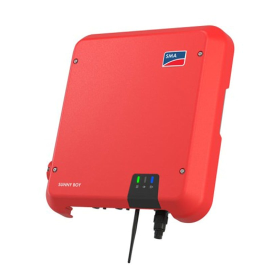
4 Product Description SMA Solar Technology AG Product Description Sunny Boy The Sunny Boy is a transformerless PV inverter with two MPP trackers which converts the direct current of the PV array to grid-compliant alternating current and feeds it into the utility grid. - Page 13 SMA Solar Technology AG 4 Product Description Position Designation LEDs The LEDs indicate the operating state of the inverter. Type label The type label uniquely identifies the inverter. The type label must remain per- manently attached to the product. You will find the following information on the type label: •...
-
Page 14: Interfaces And Functions
4 Product Description SMA Solar Technology AG Symbol Explanation Danger This symbol indicates that the inverter must be additionally grounded if additional grounding or equipotential bonding is required at the installa- tion site. Direct current The product is has no galvanic isolation. -
Page 15: Sma Speedwire
SMA Solar Technology AG 4 Product Description SMA Speedwire The inverter is equipped with SMA Speedwire as standard. SMA Speedwire is a type of communication based on the Ethernet standard. This enables inverter-optimized 10 or 100 Mbit data transmission between Speedwire devices in PV systems and the user interface of the inverter. -
Page 16: Led Signals
4 Product Description SMA Solar Technology AG All-pole sensitive residual-current monitoring unit The all-pole sensitive residual-current monitoring unit detects alternating and direct differential currents. In single-phase and three-phase inverters, the integrated differential current sensor detects the current difference between the neutral conductor and the line conductor(s). If the current difference increases suddenly, the inverter disconnects from the utility grid. - Page 17 SMA Solar Technology AG 4 Product Description Status Explanation Blue LED flashes slowly for Communication connection is being established approx. one The inverter is establishing a connection to a local network minute or is establishing a direct connection to an end device via Ethernet (e.g.
-
Page 18: Mounting
5 Mounting SMA Solar Technology AG Mounting Requirements for Mounting Requirements for the mounting location: Danger to life due to fire or explosion Despite careful construction, electrical devices can cause fires. • Do not mount the product in areas containing highly flammable materials or gases. - Page 19 SMA Solar Technology AG 5 Mounting Dimensions for mounting: 96.5 247.5 200.5 107.5 Figure 4: Position of the anchoring points (dimensions in mm (in)) Recommended clearances: If you maintain the recommended clearances, adequate heat dissipation will be ensured. Thus, you will prevent power reduction due to excessive temperature.
-
Page 20: Mounting The Inverter
5 Mounting SMA Solar Technology AG 1900 Figure 5: Recommended clearances (dimensions in mm (in)) Mounting the Inverter Additionally required mounting material (not included in the scope of delivery): ☐ 3 screws, suitable for the support surface and the weight of the inverter (diameter: minimum 6 mm) - Page 21 SMA Solar Technology AG 5 Mounting 2. Align the wall mounting bracket horizontally on the wall and mark the position of the drill holes. Use at least one hole on the right- and left-hand side and the lower hole in the middle of the wall mounting bracket.
-
Page 22: Electrical Connection
6 Electrical Connection SMA Solar Technology AG Electrical Connection Safety during Electrical Connection Danger to life due to high voltages of the PV array When exposed to sunlight, the PV array generates dangerous DC voltage, which is present in the DC conductors and the live components of the inverter. Touching the DC conductors or the live components can lead to lethal electric shocks. -
Page 23: Ac Connection
SMA Solar Technology AG 6 Electrical Connection AC Connection 6.3.1 Requirements for the AC Connection Cable requirements: ☐ External diameter: 10 mm to 14 mm ☐ Conductor cross-section: 2.5 to 6 mm² ☐ Insulation stripping length: 12 mm ☐ Sheath stripping length: 50 mm ☐... -
Page 24: Connecting The Inverter To The Utility Grid
IT system if there is no neutral conductor present and you intend to install the inverter between two line conductors. If you are uncertain about this, contact your grid operator or SMA Solar Technology AG. • Grounding conductor monitoring must be deactivated after initial start-up depending on the grid configuration (see Section 9.11, page 59). - Page 25 SMA Solar Technology AG 6 Electrical Connection 3. Shorten L and N by 8 mm each, so that the grounding conductor is 8 mm longer. This ensures that the grounding conductor is the last to be pulled from the screw terminal in the event of tensile strain.
- Page 26 6 Electrical Connection SMA Solar Technology AG 8. Fit the locking cap onto the bush insert. When doing so, position the locking cap so that the key on the locking cap is inserted into the keyway on the bush insert. 9. Lead the threaded sleeve to the bush insert and screw onto the bush insert.
-
Page 27: Connecting Additional Grounding
SMA Solar Technology AG 6 Electrical Connection 6.3.3 Connecting Additional Grounding If additional grounding or equipotential bonding is required locally, you can connect additional grounding to the inverter. This prevents touch current if the grounding conductor on the AC connector fails. The necessary ring terminal lug and the screw are included in the scope of delivery of the inverter. -
Page 28: Connecting The Network Cables
1.5 kV. Additionally required material (not included in the scope of delivery): ☐ One network cable ☐ Where required: Field-assembly RJ45 connector. SMA Solar Technology AG recommends the connector "MFP8 T568 A Cat.6A" from "Telegärtner". Cable requirements: The cable length and quality affect the quality of the signal. Observe the following cable requirements. - Page 29 SMA Solar Technology AG 6 Electrical Connection Procedure: Danger to life due to electric shock • Disconnect the inverter from all voltage sources (see Section 10, page 60). 2. When using a self-assembly network cable, assemble the RJ45 connector and connect to the network cable (see connector documentation).
-
Page 30: Mounting The Wlan Antenna
6 Electrical Connection SMA Solar Technology AG 8. Screw the swivel nut onto the threaded sleeve. 9. If you would like to establish a direct connection, connect the other end of the network cable directly to the computer. 10. If you would like to connect the inverter in a local network, connect the other end of the network cable to the local network (e. g. -
Page 31: Dc Connection
SMA Solar Technology AG 6 Electrical Connection DC Connection 6.6.1 Requirements for the DC Connection Requirements for the PV modules per input: ☐ All PV modules must be of the same type. ☐ All PV modules must be aligned and tilted identically. - Page 32 6 Electrical Connection SMA Solar Technology AG Cable requirements: ☐ Cable type: PV1-F, UL-ZKLA, USE2 ☐ External diameter: 5 mm to 8 mm ☐ Conductor cross-section: 2.5 mm² to 6 mm² ☐ Qty single wires: minimum 7 ☐ Nominal voltage: minimum 1000 V ☐ Using bootlace ferrules is not allowed. Danger to life due to high voltages on the DC conductors When exposed to sunlight, the PV array generates dangerous DC voltage which is present in the DC conductors.
-
Page 33: Connecting The Pv Array
SMA Solar Technology AG 6 Electrical Connection ☑ The stranded wire can be seen inside the clamping bracket chamber. ✖ The stranded wire cannot be seen in the chamber? The cable is not correctly in place. • Release the clamping bracket. To do so, insert a screwdriver (blade width: 3.5 mm) into the clamping bracket... - Page 34 6 Electrical Connection SMA Solar Technology AG Destruction of the measuring device due to overvoltage • Only use measuring devices with a DC input voltage range of 1000 V or higher. Damage to the DC connectors due the use of contact cleaner of other cleaning agents Some contact cleaners or other cleaning agents may contain substances that decompose the plastic of the DC connectors.
- Page 35 SMA Solar Technology AG 6 Electrical Connection 7. Connect the assembled DC connectors to the inverter. ☑ The DC connectors snap into place. 8. Ensure that all DC connectors are securely in place. Damage to the inverter due to moisture ingress If the electrical connection is not made immediately after the installation, the inverter is not sealed and moisture can penetrate the inverter.
-
Page 36: Disassembling The Dc Connectors
6 Electrical Connection SMA Solar Technology AG 6.6.4 Disassembling the DC Connectors To disassemble the DC connectors (e.g. due to faulty assembly), proceed as follows. Danger to life due to high voltages on the DC conductors When exposed to sunlight, the PV array generates dangerous DC voltage which is present in the DC conductors. - Page 37 SMA Solar Technology AG 6 Electrical Connection 5. Release the clamping bracket. To do so, insert a flat-blade screwdriver (blade width: 3.5 mm) into the clamping bracket and pry the clamping bracket open. 6. Remove the cable. Operating Manual SB30-50-1AV-40-BE-en-10...
-
Page 38: Commissioning
7 Commissioning SMA Solar Technology AG Commissioning Commissioning Procedure This section describes the commissioning procedure and gives an overview of the steps you must perform in the prescribed order. Procedure Commission the inverter. Section 7.2, page 38 Establish a connection to the user interface of the inverter. - Page 39 SMA Solar Technology AG 7 Commissioning Procedure: 1. Switch on the AC circuit breaker. 2. Turn the DC load-break switch of the inverter to position I. ☑ All three LEDs light up. The start-up phase begins. ☑ All three LEDs go out again after approximately 90 seconds.
-
Page 40: Configuring The Inverter
7 Commissioning SMA Solar Technology AG Configuring the Inverter After you have logged onto the user interface as Installer, the Configuring the Inverter page opens. Figure 8: Layout of the Configuring the Inverter page Position Designation Description Device information Provides the following information: •... - Page 41 SMA Solar Technology AG 7 Commissioning Procedure: On the Configuring the Inverter page, three configuration options are available to choose from. Select one of the three options and proceed for the selected option as described below. SMA Solar Technology AG recommends carrying out the configuration with the Installation Assistant. This way, you ensure that all relevant parameters are set for optimal inverter operation.
- Page 42 7 Commissioning SMA Solar Technology AG Configuration with the Installation Assistant (Recommended) Figure 9: Layout of the installation assistant Position Designation Description Configuration steps Overview of the installation assistant steps. The number of steps depends on the type of device and the additionally installed modules.
-
Page 43: Starting The Self-Test (For Italy Only)
SMA Solar Technology AG 7 Commissioning Procedure: 1. Select the configuration option Manual Configuration. ☑ The Device Parameters menu on the user interface will open and all available parameter groups of the inverter will be displayed. 2. Select [Edit parameters]. -
Page 44: Using The Inverter User Interface
8 Using the Inverter User Interface SMA Solar Technology AG Using the Inverter User Interface Establishing a connection to the user interface 8.1.1 Establishing a direct connection via WLAN Requirements: ☐ The inverter must be commissioned. ☐ A computer, tablet PC or smartphone with WLAN interface must be available. -
Page 45: Establishing A Direct Connection Via Ethernet
After the IP address has been confirmed by pressing the enter key, a message might appear indicating that the connection to the user interface of the inverter is not secure. SMA Solar Technology AG guarantees that calling up the user interface is secure. • Continue loading the user interface. -
Page 46: Establishing A Connection Via Ethernet In The Local Network
After the IP address has been confirmed by pressing the enter key, a message might appear indicating that the connection to the user interface of the inverter is not secure. SMA Solar Technology AG guarantees that calling up the user interface is secure. • Continue loading the user interface. -
Page 47: Logging In And Out Of The User Interface
After the IP address has been confirmed by pressing the enter key, a message might appear indicating that the connection to the user interface of the inverter is not secure. SMA Solar Technology AG guarantees that calling up the user interface is secure. • Continue loading the user interface. - Page 48 8 Using the Inverter User Interface SMA Solar Technology AG Log Out as the User or Installer 1. On the right-hand side of the menu bar, select the menu User Settings. 2. In the subsequent context menu, select [Logout]. ☑ The login page of the user interface opens. The logout was successful.
-
Page 49: Start Page Design Of The User Interface
SMA Solar Technology AG 8 Using the Inverter User Interface Start Page Design of the User Interface Figure 10: Start page design of the user interface (example) Operating Manual SB30-50-1AV-40-BE-en-10... -
Page 50: Device Configuration
8 Using the Inverter User Interface SMA Solar Technology AG Posi- Designation Description tion Menu Provides the following functions: • Home Opens the user interface homepage • Instantaneous values Current measured values of the inverter • Device Parameters The various operating parameters of the inverter can be viewed and configured here depending on the user group. - Page 51 Description tion Help Provides the following functions: • Displaying information on Open Source licenses used • Link to the website of SMA Solar Technology AG Status bar Displays the following information: • Inverter serial number • Inverter firmware version • IP addresses of the inverter within the local network and/ or IP address of the inverter during WLAN connection •...
-
Page 52: Changing The Password
8 Using the Inverter User Interface SMA Solar Technology AG Changing the Password The password for the inverter can be changed for both user groups. Furthermore, the user group Installer can change the password for the user group User as well as its own password. -
Page 53: Configuration Of The Inverter
Sunny Explorer does not support the configuration of inverters with their own user interface. The inverter can be detected via Sunny Explorer, however it is expressly not recommended to use Sunny Explorer to configure this inverter. SMA Solar Technology AG does not accept liability for missing or incorrect data and possibly resulting yield losses. -
Page 54: Starting The Installation Assistant
9 Configuration of the Inverter SMA Solar Technology AG Accepting the settings Saving the made settings is indicated by an hourglass symbol on the user interface. If the DC voltage is sufficient, the data is transferred directly to the inverter and accepted. If the DC voltage is too low (e. g. -
Page 55: Configuring The Country Data Set
SMA Solar Technology AG 9 Configuration of the Inverter Procedure: 1. Activate the user interface (see Section 8.1, page 44). 2. Log in as Installer. 3. Select the menu User Settings (see Section 8.3, page 49) on the start page of the user interface. -
Page 56: Saving The Configuration In A File
9 Configuration of the Inverter SMA Solar Technology AG Data security during activated Modbus interface If you activate the Modbus interface, there is a risk that unauthorized users may access and manipulate the data or devices in your PV system. • Take appropriate protective measures such as: –... -
Page 57: Activate Wps Function
SMA Solar Technology AG 9 Configuration of the Inverter Procedure: 1. Activate the user interface (see Section 8.1, page 44). 2. Log into the user interface as an Installer. 3. Select the menu Device Configuration. 4. Select [Settings]. 5. In the context menu, select [Adopting the configuration from a file]. -
Page 58: Switching The Dynamic Power Display Off
9 Configuration of the Inverter SMA Solar Technology AG Procedure: • To switch on the WLAN direct connection, in the parameter group PV system communication > WLAN, select the parameter Soft-access-point is turned on and set this to Yes. • To switch on the WLAN connection in the local network, in the parameter group System communication >... -
Page 59: Deactivating Grounding Conductor Monitoring
SMA Solar Technology AG 9 Configuration of the Inverter 9.11 Deactivating Grounding Conductor Monitoring If the inverter is to be installed in an IT network or another grid configuration in which deactivation of the grounding conductor monitoring is required, deactivate the grounding conductor monitoring as follows. -
Page 60: Disconnecting The Inverter From Voltage Sources
10 Disconnecting the Inverter from Voltage Sources SMA Solar Technology AG 10 Disconnecting the Inverter from Voltage Sources Prior to performing any work on the inverter, always disconnect it from all voltage sources as described in this section. Always adhere to the prescribed sequence. - Page 61 SMA Solar Technology AG 10 Disconnecting the Inverter from Voltage Sources 5. Release and remove the DC connectors. To do this, insert a flat-blade screwdriver or an angled screwdriver (blade width: 3.5 mm) into one of the slide slots and pull the DC connectors out in a downward direction.
-
Page 62: Cleaning The Inverter
11 Cleaning the Inverter SMA Solar Technology AG 11 Cleaning the Inverter Damage to the inverter due to the use of cleaning agents • If the inverter is dirty, clean the enclosure, the enclosure lid, the type label and the LEDs using only clean water and a cloth. -
Page 63: Troubleshooting
SMA Solar Technology AG 12 Troubleshooting 12 Troubleshooting 12.1 Forgotten Password If you have forgotten the password for the inverter, you can unlock the inverter with a Personal Unlocking Key (PUK). For each inverter, there is one PUK for each user group (User and Installer). -
Page 64: Event Messages
12 Troubleshooting SMA Solar Technology AG 12.2 Event Messages Event number Message, cause and corrective measures Grid fault The grid voltage or grid impedance at the connection point of the inverter is too high. The inverter has disconnected from the utility grid. - Page 65 SMA Solar Technology AG 12 Troubleshooting Event number Message, cause and corrective measures Grid fault The inverter has disconnected from the utility grid. A stand-alone grid or a very large change in the power frequency was detected. Corrective measures: • Check the grid connection for significant short-term frequency fluctuations.
- Page 66 12 Troubleshooting SMA Solar Technology AG Event number Message, cause and corrective measures Waiting for grid voltage > Grid failure > Check AC circuit breaker The AC cable is not correctly connected or the country data set is not correctly configured.
- Page 67 SMA Solar Technology AG 12 Troubleshooting Event number Message, cause and corrective measures 3401 to 3407 DC overvoltage > Disconnect generator Overvoltage at the DC input. This can destroy the inverter. This message is signalized additionally by rapid flashing of the LEDs.
- Page 68 12 Troubleshooting SMA Solar Technology AG Event number Message, cause and corrective measures 6002 to 6412 Self diagnosis > Interference device The cause must be determined by the Service. Corrective measures: • Contact the Service (see Section 15 "Contact", page 96). 6502 Self-diagnosis > Overtemperature The inverter has switched off due to excessive temperature.
- Page 69 SMA Solar Technology AG 12 Troubleshooting Event number Message, cause and corrective measures 7102 Parameter file not found or defective The parameter file was not found or is defective. The update failed. The in- verter continues feeding power into the grid.
- Page 70 12 Troubleshooting SMA Solar Technology AG Event number Message, cause and corrective measures 7331 Update transport started Update file is being copied. 7332 Update transport successful Update file was copied successfully to the inverter's internal memory. 7333 Update transport failed Update file could not be copied to the inverter's internal memory. In the event of connection with the inverter via WLAN, a poor connection quality can be the cause.
- Page 71 SMA Solar Technology AG 12 Troubleshooting Event number Message, cause and corrective measures 7348 Incorrect file format The configuration file is not of the required format or is damaged. Corrective measures: • Ensure that the selected configuration file is of the required format and is not damaged.
- Page 72 12 Troubleshooting SMA Solar Technology AG Event number Message, cause and corrective measures 7356 Update of the WebUI not successful The update of the inverter user interface failed. Corrective measures: • Retry update. • If this message is displayed again, contact the Service (see Section 15 "Contact", page 96).
- Page 73 SMA Solar Technology AG 12 Troubleshooting Event number Message, cause and corrective measures 8101 to 8104 Communication disturbed The cause must be determined by the Service. Corrective measures: • Contact the Service (see Section 15 "Contact", page 96). 9002 SMA Grid Guard code invalid The SMA Grid Guard code entered is incorrect.
- Page 74 12 Troubleshooting SMA Solar Technology AG Event number Message, cause and corrective measures 10110 Time synchronization failed: |tn0| No time information could be called up from the set NTP server. Corrective measures: • Ensure that the NTP server was configured correctly.
- Page 75 SMA Solar Technology AG 12 Troubleshooting Event number Message, cause and corrective measures 10251 [Interface]: communication status goes to [OK / Warning / Error / Not connected] The communication status to the network switch or DHCP server (router) has changed. An additional error message may be displayed.
- Page 76 12 Troubleshooting SMA Solar Technology AG Event number Message, cause and corrective measures 10255 [Interface]: Network load OK The network load has returned to a normal range after being busy. 10282 [User group]-Login via [protocol] locked After several incorrect login attempts, login has been blocked for a limited time.
- Page 77 SMA Solar Technology AG 12 Troubleshooting Event number Message, cause and corrective measures 10286 WLAN connection lost The inverter has lost WLAN connection to the selected network. Corrective measures: • Ensure that the WLAN router or WLAN Access Point is still active.
- Page 78 12 Troubleshooting SMA Solar Technology AG Event number Message, cause and corrective measures 10346 Webconnect error: Unknown SIP proxy |xx| SIP-Proxy not available. Corrective measures: • Ensure that the network cable at the inverter is correctly connected. 10347 Webconnect error: Unknown STUN server [xx] STUN server not available.
- Page 79 SMA Solar Technology AG 12 Troubleshooting Event number Message, cause and corrective measures 10353 Webconnect error: registration of the SIP registry has not responded SIP Registrar not fully available. Corrective measures: • Ensure that the network cable at the inverter is correctly connected.
-
Page 80: Checking The Pv System For Ground Faults
12 Troubleshooting SMA Solar Technology AG Event number Message, cause and corrective measures 10911 Stand. Val. [xxx] [xx] Preliminary result of the self-test 10912 Disconn. time [xx] s Preliminary result of the self-test 27103 Set parameter The parameter changes are being adopted. - Page 81 SMA Solar Technology AG 12 Troubleshooting Destruction of the measuring device due to overvoltage • Only use measuring devices with a DC input voltage range of 1000 V or higher. Procedure: In order to check the PV system for ground faults, perform the following actions in the prescribed order.
- Page 82 12 Troubleshooting SMA Solar Technology AG Example: Location of the ground fault The example shows a ground fault between the second and third PV module. 3. If a definite ground fault cannot be measured and the message is still displayed, measure the insulation resistance.
- Page 83 SMA Solar Technology AG 12 Troubleshooting Calculating the insulation resistance The expected total resistance of the PV system or of an individual string can be calculated using the following formula: total The exact insulation resistance of a PV module can be obtained from the module manufacturer or the datasheet.
-
Page 84: Updating The Firmware
12 Troubleshooting SMA Solar Technology AG 12. Recommission the inverter. 13. If the inverter still displays an insulation error, contact the Service (see Section 15 "Contact", page 96). The PV modules might not be suitable for the inverter in the present quantity. 12.4 Updating the Firmware If there is not an automatic update enabled for the inverter in the communication product (e.g. -
Page 85: Decommissioning The Inverter
SMA Solar Technology AG 13 Decommissioning the Inverter 13 Decommissioning the Inverter To decommission the inverter completely upon completion of its service life, proceed as described in this Section. Risk of injury when lifting the inverter, or if it is dropped The inverter weighs 16 kg. - Page 86 13 Decommissioning the Inverter SMA Solar Technology AG 5. Release the network cable plug and pull it out of the jack on the inverter. 6. Take the cable support sleeve out of the threaded sleeve and remove the network cable from the cable support sleeve.
- Page 87 SMA Solar Technology AG 13 Decommissioning the Inverter 10. If there is a protective cap available, plug the protective cap onto the jack for connecting the antenna. 11. If an additional grounding or an equipotential bonding is connected to the inverter, remove the pan head screw M5x12 using a Torx screwdriver (TX 25) and remove the grounding...
- Page 88 13 Decommissioning the Inverter SMA Solar Technology AG 14. Unscrew the screws for fastening the wall mounting bracket and remove the wall mounting bracket. 15. If the inverter is to be stored or shipped, pack the inverter, the AC connector, the DC connector, the RJ45 protective sleeve, the antenna and the wall mounting bracket.
-
Page 89: Technical Data
SMA Solar Technology AG 14 Technical Data 14 Technical Data 14.1 DC/AC 14.1.1 Sunny Boy 3.0 / 3.6 DC Input SB3.0-1AV-40 SB3.6-1AV-40 Maximum DC power at 3200 W 3880 W cos φ = 1 Maximum input voltage 600 V 600 V MPP voltage range 110 V to 500 V 130 V to 500 V... - Page 90 14 Technical Data SMA Solar Technology AG AC Output SB3.0-1AV-40 SB3.6-1AV-40 Rated power at 230 V, 50 Hz 3000 W 3680 W Maximum apparent AC power at cos φ = 1 3000 VA 3680 VA Rated grid voltage 230 V 230 V Nominal AC voltage 220 V / 230 V / 220 V / 230 V /...
-
Page 91: Sunny Boy 4.0 / 5.0
SMA Solar Technology AG 14 Technical Data Efficiency SB3.0-1AV-40 SB3.6-1AV-40 Maximum efficiency, η 97.0% 97.0% European weighted efficiency, η 96.4% 96.5% 14.1.2 Sunny Boy 4.0 / 5.0 DC Input SB4.0-1AV-40 SB5.0-1AV-40 Maximum DC power at cos φ = 1* 4200 W 5250 W Maximum input voltage 600 V... - Page 92 14 Technical Data SMA Solar Technology AG SB4.0-1AV-40 SB5.0-1AV-40 Nominal AC voltage 220 V / 230 V / 240 220 V / 230 V / 240 AC voltage range*** 180 V to 280 V 180 V to 280 V Nominal AC current at 220 V 18.2 A 22 A Nominal AC current at 230 V 17.4 A 22 A Nominal AC current at 240 V 16.7 A...
-
Page 93: General Data
SMA Solar Technology AG 14 Technical Data 14.2 General Data Width x height x depth 435 mm x 470 mm x 176 mm Weight 16 kg Length x width x height of the packaging 495 mm x 595 mm x 250 mm Transport weight 20.5 kg Climatic category in accordance with 4K4H IEC 60721-3-4 Environmental category Outdoors... -
Page 94: Climatic Conditions
14 Technical Data SMA Solar Technology AG Grid configurations* IT, Delta-IT, TN-C, TN-S, TN-C-S, TT (when V N_PE < 20 V) Approvals and national standards, as per AS 4777, C10/11, CE, CEI 0-21, 02/2017** DIN EN 62109 / IEC 62109, EN 50438, G59/3, G83/2, NEN EN 50438, RD1699, SI 4777, UTE C15-712, VDE0126-1-1, VDE-AR-N 4105, VFR 2014... -
Page 95: Torques
SMA Solar Technology AG 14 Technical Data AC connection AC connector WLAN As standard SMA Speedwire/Webconnect As standard 14.6 Torques Screws for securing the inverter to the wall 2.5 Nm mounting bracket Screw terminals of the AC connector 1.4 Nm Additional grounding 2.5 Nm SUNCLIX swivel nut 2.0 Nm... -
Page 96: Contact
15 Contact SMA Solar Technology AG 15 Contact If you have technical problems with our products, please contact the SMA Service Line. We require the following information in order to provide you with the necessary assistance: • Inverter device type • Inverter serial number •... - Page 97 SMA Online Service Center: www.SMA-Service.com SMA Solar (Thailand) Co., Ltd. 대한민국 SMA Technology Korea Co., Ltd. 서울 +66 2 670 6999 +82-2-520-2666 South Africa SMA Solar Technology Argentina SMA South America SPA South Africa Pty Ltd. Brasil Santiago de Chile Cape Town Chile +562 2820 2101 08600SUNNY (08600 78669) Perú...
-
Page 98: Eu Declaration Of Conformity
(LVD) • Radio and telecommunications terminal equipment (R&TTE) 1999/05/EC SMA Solar Technology AG confirms herewith that the inverters described in this document are in compliance with the fundamental requirements and other relevant provisions of the above- mentioned directives. The entire EU Declaration of Conformity can be found at www.SMA- Solar.com. - Page 100 www.SMA-Solar.com...
Need help?
Do you have a question about the SUNNY BOY 3.0 and is the answer not in the manual?
Questions and answers