Page 3
USA, contact your nearest Fluke sales or service representative. Fluke assumes no risk for damage in transit. Fluke will, at its option, repair or replace the defective product free of charge or refund the purchase price. However, if Fluke determines that the failure...
Page 4
MULTIMETER SAFETY The Fluke 10, 11, 12 Multimeters have been designed and tested according to IEC Publication 348, Safety Requirements for Electronic Measuring Apparatus. This manual contains information and warnings which must be followed to ensure safe operation and retain the meter in safe condition. Use of this equipment in a manner not specified herein may impair the protection provided by the equipment.
Table of Contents Chapter Title Page 
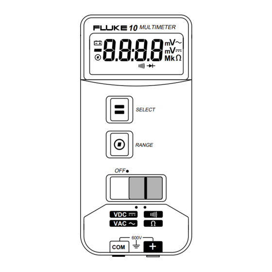
Introduction and Specifications ............1-1 1-1. Introduction................... 1-1 1-2. Specifications..................1-1 Theory of Operation ................2-1 2-1. Introduction................... 2-3 2-2. Theory of Operation................2-3 2-3. Analog Measurement IC (U1) ............2-3 2-4. Microcomputer IC (U2)..............2-3 2-5.
Page 7
Electrical Components on Main PCA ..............2-4 2-2. U1 Pinout Table ..................... 2-5 3-1. Required Equipment....................3-7 3-2. Performance Tests for Fluke 10 ................3-9 3-3. Performance Tests for Fluke 11 and 12..............3-10 4-1. Final Assembly....................... 4-5 4-2. A1 Main PCA......................4-7...
Page 9
Removing and Reinserting the Printed Circuit Assembly........3-5 3-3. Calibration Adjustment ..................3-10 4-1. Final Assembly Drawing..................4-6 4-2. A1 Main PCA Components..................4-9 4-3. Fluke 10 Schematic ....................4-10 4-4. Fluke 11 Schematic ....................4-12 4-5. Fluke 12 Schematic ....................4-14...
ELECTRIC SHOCK, PERFORM ONLY THOSE SERVICE PROCEDURES IN THIS INSTRUCTION SHEET. The 10 Series Service Manual provides the information necessary to service the Fluke Model 10, Model 11, and Model 12 Multimeters. The following information is provided in this publication: •...
Page 15
-30°C to 60°C indefinitly (to -40°C for 100 hrs) Temperature Coefficient 0.1 x (specified accuracy)/°C (<18°C or >28°C) Relative Humidity 0% to 90% (-10°C to 35°C) 0% to 70% (35°C to 50°C) Battery Type 9V, NEDA 1604 or IEC 6F22 Battery Life...
Page 16
Protection* (Nominal) Rejection Ratio Rejection (1 kΩ Unbalance) Volts DC 600V rms >10 MΩ <100 pF >100 dB at dc, 50 Hz, >50 dB at 50 Hz & LoZ = >2 kΩ or 60 Hz or 60 Hz CHEK <200 pF** >5 MΩ...
Chapter 2 Theory of Operation Title Page 2-1. Introduction................... 2-3 2-2. Theory of Operation ................2-3 2-3. Analog Measurement IC (U1) ............2-3 2-4. Microcomputer IC (U2)..............2-3 2-5. VCHEK Input Resistance..............2-3...
Introduction 2-1. Introduction Section 2 provides a basic theory of operation for the Series 10 Multimeters. Electrical components on the printed circuit assembly (A1 Main PCA) are listed in Table 2-1. Refer to Figure 4-2 for the location of these components and Figures 4-3 through 4-5 for the schematic diagrams.
10, 11, 12 Multimeters Service Manual Table 2-1. Electrical Components on Main PCA Circuit and Function Component Designator(s) Analog Measurement IC Microcomputer IC Input Divider and Ohms Reference Resistor Network Input Divider AC Coupling Capacitor J2 Input Receptable Voltage Sense Resistor...
Theory of Operation VCHEK Input Resistance Table 2-2. U1 Pinout Table Pin Name Description READ(L) When low (VSS), data from addressed register can be read. ADR5 Most significant address bus line. ADR4 Bit 4 of parallel address bus. ADR3 Bit 3 of parallel address bus. ADR2 Bit 2 of parallel address bus.
Page 22
Service Manual Table 2-2. U1 Pinout Table (cont) Pin Name Description AMPS Shunt resistor sense pin. Unused in Fluke series 10. ISRC Current source pin for continuity, ohms, and capacitance. Slide-switch position sense pin. Internal pull down. OHMS Ohms sense resistor input pin. Sense voltage at J2.
Page 23
Theory of Operation VCHEK Input Resistance POSITIVE DCV INPUT NEGATIVE DCV INPUT 10.0 500.0 |Vin| (Vdc) ana01f.eps Figure 2-1. Typical VCHEK Input Resistance with DC Volts Function Selectedcance...
Maintenance Introduction 3-1. Introduction Section 3 covers the following: • Disassembly and reassembly • Cleaning • Performance tests • Calibration 3-2. Disassembly and Reassembly WARNING TO AVOID ELECTRICAL SHOCK, REMOVE TEST LEADS AND ANY INPUT SIGNALS BEFORE OPENING THE CASE. CAUTION To avoid contamination from the fingers, handle the pca by the edges or wear gloves.
Page 27
10, 11, 12 Multimeters Service Manual WINDOW DECAL (MP3) CASE TOP (MP2) CASE TOP DECAL (MP4) LCD (U3) ELASTOMERIC CONTACT STRIP, LCD (J3) ELASTOMERIC CONTACT STRIP, SWITCH (MP9) TOP SHIELD (MP7) SWITCH ASSEMBLY (S2) SIDE-SWITCH ACTUATOR (MP5) SWITCH SUPPORT (MP6)
Page 28
Maintenance Disassembly and Reassembly SNAP SNAPS SNAP ana03f.eps Figure 3-2. Removing and Reinserting the Printed Circuit Assembly...
1. Connect the calibrator to the [+] and COM jacks on the meter. 2. Refering to Table 3-2 for the Fluke 10 or Table 3-3 for the Fluke 11 or 12, put the meter in the function and range shown for test 1.
Maintenance Calibration Table 3-1. Required Equipment Equipment Minimum Specifications Recommended Model DMM Calibrator DC Voltage: 0-600V Fluke Models (5700A, 5100B, or equivalent) Accuracy: ±0.25% AC Voltage: 0-600V Accuracy: ±0.5% Frequency: 50-400 Hz Decade Resistor Resistance: 1.0-40 MΩ General Reisistance RDS-77B and 41B Accuracy: ±0.25%...
Page 31
10, 11, 12 Multimeters Service Manual Table 3-2. Performance Tests for Fluke 10 Test No. Meter Range Input To Meter Slide-Switch Display Display Position Minimum Maximum 4.000V AC Center 0.000 0.003 4.000 AC 10 mV, 50 Hz Center 0.007 0.013 4.000 AC...
25, 26, 31, and 32) verifies that the discrete and integrated circuitry needed to support the other capacitance ranges are working within specifications. Therefore, these tests indirectly verify that the meter will meet specification in the 10 µF, 100 µF, 1000 µF, and 10,000 µF ranges. †††...
Page 33
10, 11, 12 Multimeters Service Manual CLIP TO BASE OF CONTACTS INPUT RECEPTACLES BATTERY ADJUST R4 FOR 3.997-4.003V DC anao4f.eps Figure 3-3. Calibration Adjustment 3-10...
Chapter 4 Replaceable Parts and Schematics Title Page 4-1. Introduction................... 4-3 4-2. How To Obtain Parts ................4-3 4-3. Schematics .................... 4-3 4-4. Warranty and Service Centers .............. 4-4...
Electrical components may be ordered directly from the manufacturer by using the manufacturers part number, or from the John Fluke Mfg. co., Inc. and its authorized representatives by using the part number under the heading FLUKE STOCK NO. In the U.S.
The Series 10 Multimeters are warranted for two years. The warranty is printed behind the title page of this manual. For service information, in the USA call 1-800-825-9810. Outside the USA, contact a Fluke service center. A list of service centers is at the end of Section 4.
855226 Notes Static sensitive part. 1. FOR FLUKE MODEL 10 ORDER FLUKE STOCK NUMBER 879015 FOR FLUKE MODEL 11 ORDER FLUKE STOCK NUMBER 879010 FOR FLUKE MODEL 12 ORDER FLUKE STOCK NUMBER 879007 2. FOR FLUKE MODEL 10 ORDER FLUKE STOCK NUMBER 890442...
Page 39
10, 11, 12 Multimeters Service Manual MP10 MP11 H1-4 ana05f.eps Figure 4-1. Final Assembly Drawing...
Page 41
872234 89536 872234 Notes Y Static sensitive part. 1. FOR FLUKE MODEL 10 QTY = 3 C4,11,13 FOR FLUKE MODEL 11 QTY = 3 C4,12,13 FOR FLUKE MODEL 12 QTY = 2 C4,13 2. WARNING - SAFETY RELATED COMPONENTS, USE EXACT REPLACEMENT ONLY.
Page 42
Replaceable Parts and Schematics Warranty and Service Centers ana06f.eps Figure 4-2. A1 Main PCA Components...