Fluke 12 User Manual
Hide thumbs
Also See for 12:
- User manual (33 pages) ,
- Service manual (51 pages) ,
- Quick start manual (2 pages)

Subscribe to Our Youtube Channel
Related Manuals for Fluke 12


Summary of Contents for Fluke 12
- Page 1 ® Multimeter Users Manual PN 2063508 January 2003 Rev.1, 9/04 © 2003-2004 Fluke Corporation. All rights reserved. Printed in China. All product names are trademarks of their respective companies.
-
Page 3: Table Of Contents
Table of Contents Title Page READ FIRST: SAFETY INFORMATION ............ 1 SYMBOLS ....................2 DISPLAY ....................3 OPERATING FEATURES ................4 STANDBY MODE ..................5 INPUT RANGES..................5 Autoranging..................... 6 Manually Selecting a Range..............6 MEASURING VOLTAGE ................7 TESTING CONTINUITY AND MEASURING RESISTANCE ...... 9 TESTING DIODES .................. - Page 4 12 Multimeter Users Manual Recording Minimum and Maximum Reading with Elapsed Time..... 19 Capturing Continuity Intermittents with Continuity Capture ....21 TURNING BEEPER OFF................23 MAINTENANCE..................23 N Replacing the Battery................ 23 Replacing the Test Leads................ 23 Service and Parts ..................24 Accessories .....................
-
Page 5: Read First: Safety Information
READ FIRST: SAFETY INFORMATION This meter has been designed and tested in accordance with IEC Publication 1010. To ensure that the meter is used safely, follow all safety and operating instructions in this manual. If the meter is not used as described in this manual, the safety features of the meter might be impaired. -
Page 6: Symbols
12 Multimeter Users Manual SYMBOLS The following international electrical symbols are used in this manual: W Important Safety Information in Manual Not Applicable to Identified Model Diode Capacitor Ground Double Insulation... -
Page 7: Display
12 Multimeter DISPLAY DISPLAY Figure 1. Display... -
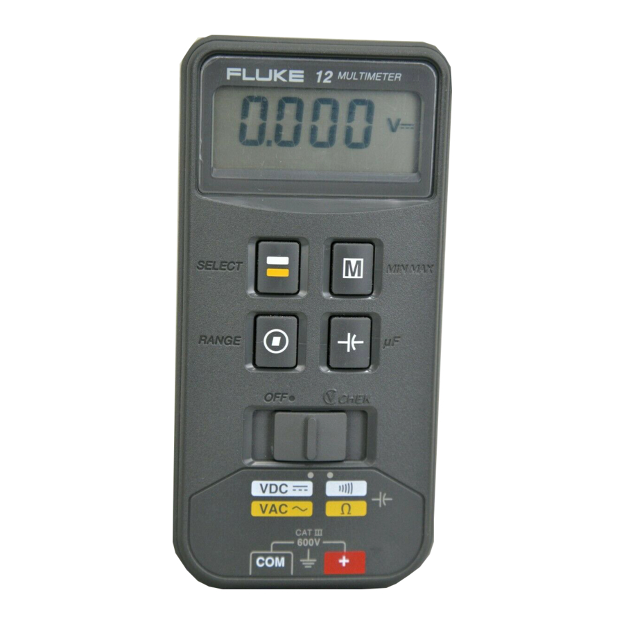
Page 8: Operating Features
12 Multimeter Users Manual OPERATING FEATURES Figure 2. Operating Features... -
Page 9: Standby Mode
12 Multimeter STANDBY MODE STANDBY MODE In standby mode, the display goes blank to preserve battery life. The meter beeps and enters Standby if it is ON but inactive for more than 45 minutes. Press any pushbutton to resume operation. Standby is not allowed if the meter is in the MIN MAX mode. INPUT RANGES The input range determines the highest value the meter will measure. -
Page 10: Autoranging
12 Multimeter Users Manual Autoranging The meter defaults to autorange when you turn it on. In autorange, the meter selects the range automatically. Manually Selecting a Range The meter also has a manual range mode. In manual range, you select and lock the meter in a range. -
Page 11: Measuring Voltage
12 Multimeter MEASURING VOLTAGE MEASURING VOLTAGE Insert the test leads in the jacks. To select a voltage function, put the slide-switch in the middle position. See Figure 3. To toggle between dc and ac, press [g]. Touch the probes to the test points, and read the display. The meter beeps an Overload Alert™... - Page 12 12 Multimeter Users Manual Figure 3. Measuring Voltage...
-
Page 13: Testing Continuity And Measuring Resistance
In ohms, read the resistance on the display. In continuity test, the beeper sounds continuously if continuity exists (resistance < 25 .). Opens and shorts longer than 250 µs are detected. On the Fluke 12, short-to-open and open-to-short transitions can be captured and visually displayed. - Page 14 12 Multimeter Users Manual Figure 4. Continuity and Resistance Measurements...
-
Page 15: Testing Diodes
12 Multimeter TESTING DIODES TESTING DIODES Insert the test leads in the jacks. Put the slide-switch in the continuity/ohms position. The meter selects either the continuity/diode (R G) or ohms (e) function. If ohms is selected, press [g] to toggle to the continuity/diode function. To toggle the beeper on or off in continuity/diode test, press [V]. - Page 16 12 Multimeter Users Manual Figure 5. Testing Diodes...
-
Page 17: Vchek And How To Use It
12 Multimeter VCHEK AND HOW TO USE IT VCHEK AND HOW TO USE IT i is a subset of the continuity/ohms function. In i, the meter is designed to automatically display an ac or dc voltage when the meter detects a voltage greater in magnitude than about 4.5 V and the meter is not in the manual range mode. -
Page 18: Disabling I With Function Lock
12 Multimeter Users Manual Use i only on power supplies and other power sources that have a low output impedance. Do not use i to measure voltage in electronic circuitry unless a 2 ke load will not damage the circuit. See † on page 27. DISABLING i WITH FUNCTION LOCK To lock the meter in either the continuity/diode or ohms function, and disable i: Put the slide-switch in the continuity/ohms position. -
Page 19: Measuring Capacitance
12 Multimeter MEASURING CAPACITANCE MEASURING CAPACITANCE First, turn off power to the circuit, and disconnect and discharge the capacitor. Insert test leads, and move the slide-switch to [E]. (See Figure 6.) Press [E]. The capacitance function is selected and µF is displayed. Touch the probes to the capacitor. - Page 20 12 Multimeter Users Manual Figure 6. Measuring Capacitance...
-
Page 21: Using Min Max Functions
12 Multimeter USING MIN MAX FUNCTIONS USING MIN MAX FUNCTIONS Recording Minimum and Maximum Readings MIN MAX records the highest and lowest measurements taken. MIN MAX cannot be used when the meter is measuring capacitance. In the MIN MAX mode, autoranging, Standby, and i are disabled. -
Page 22: Multimeter Users Manual
12 Multimeter Users Manual Figure 7. Displaying Minimum and Maximum Reading... -
Page 23: Recording Minimum And Maximum Reading With Elapsed Time
12 Multimeter USING MIN MAX FUNCTIONS Recording Minimum and Maximum Reading with Elapsed Time The MIN MAX with elapsed-time mode records the time (in hours and minutes) between when MIN MAX was entered and the last high and low was recorded. Time is kept to 99:59. - Page 24 12 Multimeter Users Manual Figure 8. Maximum and Minimum Reading with Elapsed Time...
-
Page 25: Capturing Continuity Intermittents With Continuity Capture
12 Multimeter USING MIN MAX FUNCTIONS Capturing Continuity Intermittents with Continuity Capture When testing continuity, the meter can capture intermittents as short as 250 µs, and display them as open-to-short and short-to-open transitions. Put the slide-switch in the continuity/ohms position. Connect the leads to the circuit. - Page 26 12 Multimeter Users Manual Figure 9. Open-to-Short and Short-to-Open Transitions...
-
Page 27: Turning Beeper Off
Remove the battery from case bottom. Replacing the Test Leads The meter uses double-insulated test leads. When replacing the test leads, order Fluke PN 855742 only. -
Page 28: Service And Parts
This meter should be serviced only by a qualified service technician. To order the service manual (PN 900824) and other parts or for service information, in the USA call 1-800-825-9810. Outside the USA, contact the nearest Fluke service center. Accessories When using accessories, put the slide-switch in the volts position, and manually select the 4000 mV range for ease of reading. - Page 29 12 Multimeter SPECIFICATIONS Maximum Voltage Between any Terminal and Earth Ground 600 V rms Display 3 3/4-digits, 4000 counts, updates 4/sec Operating Temperature -10 °C to 50 °C Storage Temperature -30 °C to 60 °C indefinitely (to -40 °C for 100 hrs) Temperature Coefficient 0.1 x (specified accuracy)/°C (<18 °C or >28 °C) Relative Humidity...
- Page 30 12 Multimeter Users Manual Function Range Resolution Accuracy (50 to 400 Hz) 4000 mV* 1 mV ±(1.9 %+3) 4.000 V 0.001 V ±(1.9 %+3) 40.00 V 0.01 V ±(1.9 %+3) 400.0 V 0.1 V ±(1.9 %+3) 600 V ±(1.9 %+3) 4000 mV* 1 mV ±(0.9 %+2)
- Page 31 12 Multimeter SPECIFICATIONS Function Overload Input Common Mode Normal Mode Protection* Impedance Rejection Ratio Rejection (Nominal) (1 k Unbalance) 600 V dc >10 M 100 pF >100 dB at dc, >50 dB at †i & LoZ = 50 Hz or 60 Hz 50 Hz or 60 Hz >2 k <200 pF...
- Page 32 12 Multimeter Users Manual...
Need help?
Do you have a question about the 12 and is the answer not in the manual?
Questions and answers
Para medir amperaje?
Francisco