
Subscribe to Our Youtube Channel
Related Manuals for Lenz Digital Plus STANDARD PLUS V2


Summary of Contents for Lenz Digital Plus STANDARD PLUS V2
- Page 1 Information STANDARD+ V2 (Art.Nr. 10231-02) 3. Auflage / 3 Edition / 3. Edition 05 16 B.B.10.0016-3...
- Page 2 Information STANDARD+ V2 Decoder Technische Daten / Technical Data / Données techniques: Maximale Maximum continuous Charge totale 1,0 A Dauerbelastbarkeit des current-carrying maximale autorisée gesamten Decoders capacity of total du décodeur decoder Motorausgang Motor output Sortie moteur 1,0 A Funktionsausgänge Function outputs Sorties de fonction je/resp.
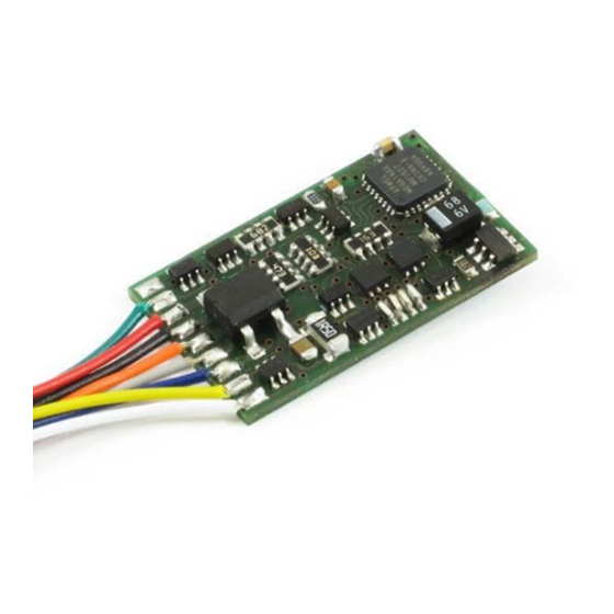
- Page 3 Abb. 1: Anschluss des STANDARD+ V2 Decoders mit Kabeln The connection of the STANDARD+ V2 decoder with cables Raccordement du décodeur STANDARD+ V2 avec câbles...
- Page 4 Information STANDARD+ V2 Decoder Kontaktbelegung der NEM652 Schnittstelle Pin allocations of the NEM652 interface Attribution des contacts de l'interface NEM652 Orange Pin 1 Bedeutung Meaning Signification Motoranschluß 1 Motor connection 1 Sortie moteur 1 Licht hinten (-) (F-Ausg. rear headlight (Function Feux sign.
- Page 5 Nicht geeignet für Kinder unter 14 Jahren wegen verschluckbarer Kleinteile. Bei unsachgemäßem Gebrauch besteht Verletzungsgefahr durch funktionsbedingte Kanten und Spitzen! Nur für trockene Räume. Irrtum sowie Änderung aufgrund des technischen Fortschrittes, der Produktpflege oder anderer Herstellungsmethoden bleiben vorbehalten. Jede Haftung für Schäden und Folgeschäden durch nicht bestimmungsgemäßen Gebrauch, Nichtbeachtung dieser Gebrauchsanweisung, Betrieb mit nicht für Modellbahnen zugelassenen, umgebauten oder schadhaften Transformatoren bzw.
- Page 6 Information STANDARD+ V2 Decoder Les appareils numériques sont non indiqués pour les enfants en dessous de 14 ans en raison des petites pièces susceptibles d'être avalées. En cas d'utilisation incorrecte existe un danger de blessures dues à des arêtes vives ! Les appareils sont uniquement utilisables dans des locaux secs.
- Page 7 Wichtige Sicherheitshinweise: Digital plus Lokdecoder dürfen ausschließlich mit dem Digital plus by Lenz System oder einer anderen handelsüblichen Digitalsteuerungen mit NMRA-Konformitäts-Siegel verwendet werden. Fragen Sie im Zweifelsfall beim Lieferanten des Systems nach. Die in den technischen Daten angegebenen Belastbarkeiten dürfen nicht überschritten werden. Sie müssen sicherstellen, dass diese maximale Belastbarkeit nicht überschritten wird.
- Page 8 Information STANDARD+ V2 Decoder Einbau des Decoders mit Kabelanschluss (Abb. 1, S. 3.) Notieren Sie sich, welcher Motoranschluß mit den rechten und welcher mit den linken Radschleifern verbunden ist. Dies erspart Ihnen beim Anschluß des Decoders Versuche, welches Kabel des Decoders an welchen Motoranschluß...
- Page 9 Sind die Glühbirnchen nicht elektrisch mit dem Chassis der Lokomotive verbunden (wir nennen diese dann "potentialfrei"), so schließen Sie den anderen Pol der Lampen an das blaue Kabel an, wie in der Abb. 1 zu sehen ist. Besteht eine Verbindung zwischen Glühbirnen und Chassis, so bleibt das blaue Kabel unbenutzt.
- Page 10 Im Folgenden geben wir Ihnen einen kurzen Überblick über die Eigenschaften der Decoder und deren Einstellung. Ausführliche Informationen zu den Eigenschaften und deren Einstellungen finden Sie im "Handbuch Plus-Decoder" welches Sie von der Website der Lenz Elektronik GmbH herunterladen können: www.lenz-elektronik.de/pdf/download.php 5.1 Schutzeinrichtungen Der Decoder ist gegen Überlast, Kurzschluß...
- Page 11 als auch die Regelung abgeschaltet werden. Weiterhin steht die CV9 zur Anpassung der Wiederholrate zur Verfügung. Die minimale (CV2), maximale (CV5) und mittlere (CV6) Geschwindigkeit kann eingestellt werden, der Decoder passt die Geschwindigkeitskennlinie dabei dynamisch an, um einen sanften Verlauf ohne Knickstellen zu gewährleisten.
- Page 12 Sie aktivieren Sie den konstanten Bremsweg bei Fahrstufe 0 durch Setzen des Bit 8(7) in der CV51 Ausführliche Informationen zur Einstellung des Bremsweges finden Sie im „Handbuch Plus-Decoder“, welches Sie von der Website der Lenz Elektronik GmbH herunterladen können: www.lenz-elektronik.de/pdf/download.php Weitere wichtige Hinweise: ...
- Page 13 Während der Rangiergang eingeschaltet ist (Standardeinstellung F3), ist der konstante Bremsweg abgeschaltet, es wirkt die Verzögerung aus CV3. Der konstante Bremsweg ist ebenfalls abgeschaltet, wenn die Verzögerungen im Decoder per Funktion (Standardeinstellung F4) ausgeschaltet sind. Die beiden letztgenannten Eigenschaften können Sie z.B. auch dann sinnvoll einsetzen, wenn Sie einen bereits begonnenen Bremsvorgang vorzeitig abbrechen wollen.
- Page 14 Information STANDARD+ V2 Decoder Ist der Rangiergang eingeschaltet oder sind die Verzögerungen ausgeschaltet, so ist die ABC- Technik nicht aktiv! 5.8 Pendelzugsteuerung Bei Einsatz der ABC-Bremsmodule ist eine Pendelzugsteuerung einstellbar. Zwei verschiedene Optionen gibt es hierbei: Pendeln mit und ohne Zwischenhalt. Im zweiten Modus werden auch Langsamfahrabschnitte berücksichtigt.
- Page 15 Leistung (Kickdauer), nach Ablauf dieser Zeit eine reduzierte Leistung zur Verfügung. Wie weit die Leistung reduziert wird, ist ebenfalls einstellbar. Außerdem können Sie einstellen, ob die Lok während des Kupplungsvorgangs fährt und wie lange. 5.12 RailCom Der Decoder ist mit der RailCom Funktion ausgerüstet. Es können neben der Lokadresse auch weitere Daten (z.B.
- Page 16 Information STANDARD+ V2 Decoder Einstellung des Decoders Lokadresse, Anfahr- und Bremsverzögerung sowie alle anderen Eigenschaften des Decoders können durch PROGRAMMIERUNG beliebig oft geändert werden. Diese Eigenschaften werden im Decoder dauerhaft, also auch beim Abschalten der Betriebsspannung, "aufgehoben". In der (amerikanischen) Normung werden die Speicher als "Configuration Variable", kurz: "CV" bezeichnet.
- Page 17 1-127 Basis – Lokadresse ® Dies ist die Nummer, mit der Sie die Loks im Digital plus by Lenz ® System aufrufen. Für die Verwendung mit Digital plus by Lenz Geräten ist nur der Bereich 1-99 zugelassen. Beim Schreiben...
- Page 18 Information STANDARD+ V2 Decoder RailCom Konfiguration 3 (dec) 1 (0) Kanal 1 freigegeben für Adress-Broadcast 2 (1) Kanal 2 freigegeben für Daten und Acknowledge Einstellungen 1 14 (dec) 1 (0) Richtung der Lok normal: Lok fährt nach vorne, wenn der Pfeil auf dem Handregler nach oben zeigt.
- Page 19 6 (5) Decoder verwendet Basisadresse (aus CV1) Decoder verwendet erweiterte Adresse (aus CV17 u. CV18) 7-8(6-7) nicht verwendet Fehleranzeige 1 (0) Lampen- Kurzschluss 2 (1) Übertemperatur 3 (2) Motor-/Gleis- Kurzschluss Werte- Funktionszuordnung (Mapping) für Funktionsausgänge: Werks- bereich Um eine Funktion des Digitalsystems einem Funktionsausgang einstellung zuzuordnen sucht man den Schnittpunkt der Zeile der gewünsch- –...
- Page 20 Information STANDARD+ V2 Decoder 0-31 Funktion 8 0-31 Funktion 9 0-31 Funktion 10 0-31 Funktion 11 0-31 Funktion 12 0-31 Funktion 1 rückwärts Motor - Konfiguration 0 (dec) 1-4 (0-3) Auswahl des Motortyps 0-5, Eingabe als Dezimalzahl 6 (5) EMK-Teiler nicht aktiv EMK-Teiler aktiv 7 (6) Regelung eingeschaltet...
- Page 21 0-255 Bremsweg bei aktiviertem konstanten Bremsweg 0-255 Langsamfahrt bei ABC 0-255 Aufenthaltsdauer bei Pendelbetrieb, 1 bis 256 Sekunden 0-255 stellt die Helligkeit am F-Ausgängen A ein, 255=max 0-255 stellt die Helligkeit am F-Ausgängen B ein, 255=max Funktionszuordnung (Mapping): Jedes Bit der CV steht für eine Funktion des Digitalsystems: Bit 1(0) für Funktion 1, Bit 2(1) für Funktion 2 und so weiter bis Bit 8(7) für Funktion 8.
- Page 22 Information STANDARD+ V2 Decoder Zehnerstelle des Wertes für F- Einerstelle des Wertes für F- Ausgang D: Ausgang C: kein Effekt kein Effekt Blinken im Gleichtakt zu Blinken F-Ausgang C Flackern Typ 1 (ruhig) Blinken im Gegentakt zu F-Ausgang C Flackern Typ 2 (unruhiger) Flackern Typ 3 (hektisch) Blinkfrequenz für F-Ausgänge C und D: für eine bestimmte Frequenz (f) ergibt sich der Wert ins CV63 aus...
- Page 23 0-255 Transport CV für SUSI Servicenummer (aktuelle Nummer bitte auslesen) Funktionszuordnung F13 – F28 zu den Ausgängen Funktionsausgang: 0-31 Funktion 13 0-31 Funktion 14 0-31 Funktion 15 0-31 Funktion 16 0-31 Funktion 17 0-31 Funktion 18 0-31 Funktion 19 0-31 Funktion 20 0-31 Funktion 21...
- Page 24 Information STANDARD+ V2 Decoder 0-16 Funktionszuordnung Kupplungssteuerung rückwärts Funktionsausgang: 0-255 „Kickdauer“: Einstellbar in Vielfachen von 0,016 Sekunden. Die Werkseinstellung enspricht 30x0,016 Sekunden = 0,48 Sekunden 0-255 Verfahren der Lok beim Entkuppeln vom Wagen weg. Einstellbar in Vielfachen von 0,016 Sekunden. Die Werkseinstellung enspricht 80x0,016 Sekunden = 1,28 Sekunden 0-255 Verfahren der Lok beim Entkuppeln zum Wagen hin.
- Page 25 Important safety instructions Digital plus locomotive decoders are to be used only with Lenz Digital plus or other standard digital control systems with an NMRA-conformance seal. If in doubt, ask the system supplier. Please note that the maximum current-carrying capacity of the outputs may not be exceeded as this...
- Page 26 Information STANDARD+ V2 Decoder Installing the decoder via cable connection (Abb. 1, p. 3.) Please note which motor connection is linked to the right rail pickups and which to the left. If you do this you will not have to try out which decoder cable needs to be soldered to which motor connection to achieve the desired direction of travel.
- Page 27 function output A (white cable) to the bulb which is at the front in relation to the direction of travel function output B (yellow cable) to the bulb which is at the back in relation to the direction of travel If the functions inside the locomotive (e.g.
- Page 28 Information STANDARD+ V2 Decoder Installing the STANDARD+ V2 decoder via interface plug NEM652 (Abb. 2, p. 4) These decoders come with a NEM652 / NMRA RP-9.1.1 medium plug. This plug makes the installation of these decoders very simple. To install the decoder simply remove the dummy plug in your locomotive and install the decoder plug.
- Page 29 You can find detailed information on the features and their settings in the “Manual Plus Decoders” that you can download from the Lenz Elektronik GmbH website www.lenz- elektronik.de 5.1 Capacity and protection equipment The decoder is protected against overloading, short circuits and overheating. In case of a fault, the corresponding bit is set in CV30 which will state the type of fault which has occured.
- Page 30 Information STANDARD+ V2 Decoder 5.3 Running notches (Speed steps) The decoder can be operated in the 14/27 or the 28/128 running-notches mode. This setting is made in CV29. 5.4 Disabling of delay Use function 4 (ex-works setting, can be altered in CV60) to disable the starting and braking delay as well as the constant braking distance during operation.
- Page 31 You can find detailed information on setting the braking distance in the “Manual Plus Decoders” that download from Lenz Elektronik GmbH website www.lenz- elektronik.de/pdf/download.php Important advice: The length of the covered braking distance is set in CV52. The braking distance differs depending on the value set in this CV.
- Page 32 Information STANDARD+ V2 Decoder signal. The decoder reacts to this. Combined with the constant braking distance, precise on-the- spot stopping in front of red signals is not a problem. Of course, passage in the opposite direction is also possible. The signal indication "slow approach/caution" does not pose a problem; the respective maximum-speed can be set in CV53.
- Page 33 5.11 Coupling control The decoder allows for a comfortable controlling of remote couplings at all function outputs. The selected output provides full power for a settable period of time (kick duration) and reduced power after this period has expired. By how much the power is decreased can be set using the value for brightness for the choosen output.
- Page 34 Information STANDARD+ V2 Decoder For detailed instructions on how to program using the above-mentioned devices, please refer to the operating manuals which accompany those devices. The decoder is programmed ex-works for operation with address 3 and 28 running notches. The decoder can be used with these basic configurations immediately after purchase.
- Page 35 Ex-works Meaning setting 1-127 Basic locomotive address. This number is used to call up ® locomotives in the Digital plus by Lenz system. The use of range 1-99 is recommended for operation with ® Digital plus by Lenz devices. When writing this CV, CV19 (multiple traction address) is automatically deleted in the decoder and Bit 6 (use of extended address) is deleted in CV29.
- Page 36 Information STANDARD+ V2 Decoder Settings 1 6 (dec) 1 (0) Direction of travel normal: locomotive drives forward if the arrow on the manual control points up. interchanged: locomotive drives forward if the arrow on the manual control points down. 2 (1) Running-notches mode: Operation with 14 or 27 running notches.
- Page 37 1 (0) Light short-circuit 2 (1) Overheating 3 (2) Motor-/Track short-circuit Range of Function mapping for function outputs: Ex-works values In order to allocate a function of the digital system to a function setting output, look for the section where the row of the desired function –...
- Page 38 Information STANDARD+ V2 Decoder 0-31 Function 1 backward Motor configuration 0 (dec) 1-4 (0-3) Select motor type 0-5, enter as decimal number 6 (5) EMF switch inactive EMF switch active 7 (6) Control switched on Control switched off 8 (7) High-frequency motor control (approx.
- Page 39 Function mapping: Each bit of the CV stands for a function of the digital system: Bit 1(0) for function 1, Bit 2(1) for function 2 and so on up to Bit 8(7) for function 8. If you wish to allocate a function to the dimming, the respective bit must be set.
- Page 40 Information STANDARD+ V2 Decoder Flickering type 2 (less smooth) Flickering type 3 (excitedly) Flashing frequency for function outputs C and D: default approx. 1 sec, f = 1 / ( 0.03 * (1 + CV63)) Function mapping: lighting effect at function outputs C and D 0-255 Values for characteristic speed line 67..
- Page 41 0-31 Function 18 0-31 Function 19 0-31 Function 20 0-31 Function 21 0-31 Function 22 0-31 Function 23 0-31 Function 24 0-31 Function 25 0-31 Function 26 0-31 Function 27 0-31 Function 28 Function allocation coupling control forward Function output: Function allocation coupling control backward Function output: 0-255...
- Page 42 Information STANDARD+ V2 Decoder 0-255 Locomotive movement during decoupling towards the coach. Settable in multiples of 0.016 seconds. The default setting is 80x0.016 seconds = 1.28 seconds.
- Page 43 Remarques importantes Tout décodeur Digital plus est exclusivement destiné à être utilisé avec Lenz DIGITAL plus ou un autre système de pilotage digital du commerce portant le sigle de compatibilité NMRA. En cas de doute, demandez des explications au revendeur du système.
- Page 44 Information STANDARD+ V2 Decoder décodeur vous devrez souder aux bornes de sortie du moteur pour que la locomotive roule dans le bon sens. Les sorties du moteur doivent être au potentiel zéro après enlèvement des câbles préexistants. Cela signifie qu'il ne doit subsister aucune liaison avec le châssis ou avec les roues (ou patins de roue).
- Page 45 Si vous êtes d'accord d'utiliser les sorties de fonction telles que réglées en usine, raccordez alors les sorties comme suit : sortie A (câble blanc) à l'ampoule avant (selon sens de marche sélectionné) ; sortie B (câble jaune) à l'ampoule arrière (selon sens de marche sélectionné). Si le second pôle des ampoules n'est pas relié...
- Page 46 Dans ce qui suit, nous vous donnons un aperçu des propriétés du décodeur GOLD+ et des réglages possibles. Vous trouverez dans le "Manuel Décodeurs-Plus" des informations détaillées à propos des propriétés et de leur paramétrage. Ce manuel est téléchargeable sur le site Internet de Lenz Elektronik GmbH : www.lenz-elektronik.de.
- Page 47 5.1 Puissance et sécurité Le décodeur est protégé contre les surcharges, les courts-circuits et les surchauffes. En cas d'erreur, un bit correspondant est inscrit dans la CV 30, lequel donne une information au sujet du genre d'erreur. Ce bit peut être effacé par programmation. 5.2 Commande du moteur Le décodeur dispose d'un contrôle du moteur à...
- Page 48 Information STANDARD+ V2 Decoder maximale plus élevée ; simultanément, la vitesse minimale augmentera également, mais dans une faible mesure. 5.3 Crans de vitesse Le décodeur peut être exploité avec les modes de marche à 14/27 ou 28/128 crans de vitesse. Le réglage se fait au moyen de la CV 29.
- Page 49 (7) dans la CV 51. Vous trouverez dans le "Manuel Décodeurs-Plus" des informations détaillées à propos du paramétrage de la distance de freinage. Ce manuel est téléchargeable sur le site Internet de Lenz Elektronik GmbH : www.lenz-elektronik.de/pdf/download.php. Remarques importantes : La fonction "distance de freinage constante"...
- Page 50 Information STANDARD+ V2 Decoder 5.6 Mode de marche "manœuvre" Le mode de marche "manœuvre" réduit la vitesse de moitié. Une régulation particulièrement fine en résulte et permet d'effectuer des manœuvres en douceur. A l'aide de la touche de fonction 3 (réglage d'usine pouvant être modifié...
- Page 51 5.8 Navette ferroviaire L'utilisation des modules ABC permet la gestion d'une navette. Il existe dans ce cas deux options : navette avec ou sans arrêt intermédiaire. Dans le second cas, il faut aussi prendre en considération les sections de ralentissement. Le pilotage d'une navette est activé...
- Page 52 Information STANDARD+ V2 Decoder 5.12 RailCom Le décodeur est équipé de la fonction RailCom. Celle-ci permet au décodeur de renvoyer au système digital, via la voie, d'autres informations que l'adresse de locomotive, telles que la vitesse en cours, le contenu de CV, … Les informations envoyées sont captées par un détecteur RailCom et rendues visibles sur un écran d'affichage.
- Page 53 1-127 Adresse de base de locomotive. Ceci est le numéro avec lequel vous appelez la locomotive dans ® le système Digital plus by Lenz . Pour une utilisation avec les ® appareils Digital plus by Lenz , seules les adresses 1-99 sont permises.
- Page 54 Information STANDARD+ V2 Decoder 0-255 Adresse de loco étendue, byte de niveau le plus faible. 0-99 Adresse de multitraction. Configuration RailCom 3(déc.) 1 (0) Canal 1 autorisé pour "Adress-Broadcast" 2 (1) Canal 2 autorisé pour données et admission instruction Réglages de niveau 1 6 (déc.) 1 (0) Sens de marche de la locomotive :...
- Page 55 4 (3) Envoi RailCom désactivé Envoi RailCom activé 5 (4) Courbe caractéristique de vitesse encodée en usine Courbe caractériser. de vitesse définie par l'utilisateur 6 (5) Le décodeur utilise l'adresse de base (en CV 1). Le décodeur utilise l'adresse étendue (en CV 17 et 18). 7-8 (6-7) Non utilisé.
- Page 56 Information STANDARD+ V2 Decoder 0-31 Fonction 3 0-31 Fonction 4 0-31 Fonction 5 0-31 Fonction 6 0-31 Fonction 7 0-31 Fonction 8 0-31 Fonction 9 0-31 Fonction 10 0-31 Fonction 11 0-31 Fonction 12 0-31 Fonction 1 arrière Configuration moteur 0 (déc.) 1-4 (0-3) Choix du type de moteur 0-5, entrée en nombre décimal.
- Page 57 désactivé 4 (3) Exploitation en navette sans arrêt intermédiaire activée 5 (4) Exploitation en navette avec arrêt intermédiaire activée 6 (5) Arrêter avec le courant continu indépendamment de la polarité (n'est pris en compte que si le bit 3 est éteint dans la CV29) 7 (6) Bit non utilisés...
- Page 58 Information STANDARD+ V2 Decoder 0-255 Désactivation de la temporisation (touche F4 encodée en usine) 0-255 Effets lumineux aux sorties de fonction A et B: Le chiffre des dizaines vaut Le chiffre des unités vaut pour pour la sortie B la sortie A Aucun effet Aucun effet Marslight (gyrophare lent)
- Page 59 (nerveux) Fréquence de clignotement pour les sorties de fonction C et D : par défaut, env. 1 seconde. f = 1 / ( 0,03 * (1 + CV 63)) Attribution des fonctions aux sorties de fonction C et D pour la commande des effets lumineux 0-255 Valeurs pour la courbe caractéristique de vitesse.
- Page 60 Information STANDARD+ V2 Decoder 0-31 Fonction 15 0-31 Fonction 16 0-31 Fonction 17 0-31 Fonction 18 0-31 Fonction 19 0-31 Fonction 20 0-31 Fonction 21 0-31 Fonction 22 0-31 Fonction 23 0-31 Fonction 24 0-31 Fonction 25 0-31 Fonction 26 0-31 Fonction 27 0-31...
- Page 61 0-255 La durée de pleine puissance est réglable sur une série de valeurs multiples de 0,016 secondes. Le réglage d'usine correspond à 30 x 0,016 s = 0,48 s. 0-255 L'avancement de la locomotive lors du dételage est réglable sur une série de valeurs multiples de 0,016 secondes.
- Page 62 Information STANDARD+ V2 Decoder Diese Seite ist absichtlich frei.
- Page 63 Diese Seite ist absichtlich frei.
- Page 64 Vogelsang 14 D - 35398 Gießen Hotline: 06403 900 133 Fax: 06403 900 155 http://www.digital-plus.de http://www.lenz-elektronik.com e-mail: info@digital-plus.de Diese Betriebsanleitung bitte für späteren Gebrauch aufbewahren! Keep this operation manual for future reference! Conservez ce manuel pour une utilisation ultérieure !
Need help?
Do you have a question about the Digital Plus STANDARD PLUS V2 and is the answer not in the manual?
Questions and answers