Table of Contents
Advertisement
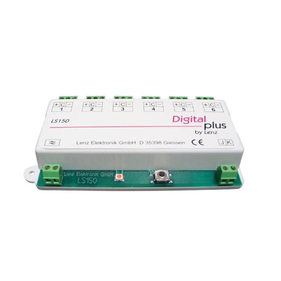
Accessory decoder LS150
The DIGITAL plus LS150 turnout decoder provides cost effective turnout control for
up to 6 independent turnouts.
∗
Suitable for twin-coil snap action switch machines
∗
Suitable for motorized switch machines
∗
High current provision to support Peco and Atlas switch machines
∗
The 6 turnout addresses can be sequential or up to 6 user selected
addresses.
∗
Control using separate push-buttons possible.
∗
Configuring the LS150 does not require a separate programming track and the
parameters can be changed at any time in the future even after installation.
LS150
Turnout Decoder for up to 6
independent turnouts
Art. No. 11150
December 2003
Submitted to the NMRA for
C&I testing
1
Advertisement
Table of Contents

Related Manuals for Lenz Digital Plus LS150


Summary of Contents for Lenz Digital Plus LS150
-
Page 1: Ls150 Turnout Decoder For Up To 6 Independent Turnouts
Accessory decoder LS150 The DIGITAL plus LS150 turnout decoder provides cost effective turnout control for up to 6 independent turnouts. ∗ Suitable for twin-coil snap action switch machines ∗ Suitable for motorized switch machines ∗ High current provision to support Peco and Atlas switch machines ∗... -
Page 2: Table Of Contents
Accessory decoder LS150 Contents LS150 Turnout Decoder for up to 6 independent turnouts ........1 Contents........................2 Important advice, please read first! ................3 Use of the LS150 .....................3 Technical data......................4 Outputs of the LS150...................4 Power and DCC signal Inputs of the LS150 ............6 Connecting the LS150....................7 Connection to the AC power supply ..............7 Connection to the NMRA DCC digital system .............8... -
Page 3: Important Advice, Please Read First
Accessory decoder LS150 Important advice, please read first! ® The LS150 is a component of the Digital plus by Lenz system and was submitted to intensive testing before delivery. Lenz Elektronik GmbH guarantees fault-free operation provided you follow the advice given below:... -
Page 4: Technical Data
Accessory decoder LS150 Technical data 6 connections for controlling 6 turnouts LS150 by Lenz Lenz Elektronik GmbH D 35398 Giessen Push- Connection to track Transformer button outputof the connection digital system Range of addresses 1 - 1024 Max. voltage on AC input 16 V Max. - Page 5 Accessory decoder LS150 tracks etc.) can be connected to a LS150 and controlled individually. Pulse Duration Having received a turnout command for an output, this output will be switched on. It will remain so as long as the turnout command is being sent.
-
Page 6: Power And Dcc Signal Inputs Of The Ls150
(Radio shack part #271-1101) The track outputs of a digital system (J,K for ® Digital plus by Lenz systems) must not be used to supply the LS150 with power! The LS150 receives its commands to activate a turnout from the NMRA-DCC digital system track outputs connected to the LS150’s... -
Page 7: Connecting The Ls150
Motorized switch machine machine Coil 1 Coil 2 LS150 by Lenz Lenz Elektronik GmbH D 35398 Giessen AC transformer to the track output of connection the digital system Figure 1 Connection to the AC power supply Please see Figure 1 (Page 7), bottom left: Connect the terminals (≈) to the terminals of an AC transformer. -
Page 8: Connection To The Nmra Dcc Digital System
Please see Figure 1 (Page 7), bottom right: Connect the terminals J, K with the track output of the digital ® system. In the Digital plus by Lenz system the track output is also marked with J and K. Connecting twin-coil switch machines Please see Figure 1 (Page 7), top left: Twin-coil switch machines have three connections. -
Page 9: Connecting Motorized Switch Machines
Accessory decoder LS150 Connecting motorized switch machines Please see Figure 1 (Page 7), top right: Motorized drives (such as Kato Unitrak, and Circuitron Tortoise) normally require DC voltage for operation. By reversing this DC voltage, the direction of rotation of the motor is changed and thus the turnout is set to a different position. -
Page 10: Connecting A Separate Push-Button To The Ls150
Twin-coil Coil 1 Coil 2 switch machine LS150 Lenz Elektronik Gmb transformer connection Figure 2 The figure shows a typical twin-coil switch machine. The two coils are connected to the terminals + and - of an output of the LS150. -
Page 11: Controlling The Outputs
Accessory decoder LS150 the right (marked with in Figure 2) otherwise the turnout will not function properly! Press push-button K1 to activate coil 1 and press push-button K2 to activate coil 2. This way you can control the turnout both digitally with the LS150 or manually with the push-buttons K1 and Only use voltage-free contacts for this procedure, e.g. -
Page 12: Setting The Address
(such your ® Digital plus by Lenz system.) 1. Choose the turnout address which you wish to set the first output of the LS150 to. 2. Press the push-button on the LS150 and keep it down until the LED shines continuously (this will take approx. -
Page 13: Setting Individual Addresses And Pulse Durations Of Outputs
Connect the LS150 to both the AC voltage supply and track output as described in the Section "Connecting the LS150" (Page 7). ® Then turnout on your Digital plus by Lenz system. Complete the following steps to set the address and pulse duration of an output. -
Page 14: Resetting The Decoder
Accessory decoder LS150 second output. To set this output, go back to step 3. Repeat this procedure for all outputs of the LS150. To complete the setting process at any time, press and hold the push-button until the LED turns off. If you want to skip a certain setting, simply press the key again and the LS150 will proceed to the next step. - Page 15 Accessory decoder LS150 This page has been left blank deliberately...
-
Page 16: North American Warranty
Accessory decoder LS150 North American Warranty Lenz GmbH does everything it can do to ensure that its products are free from defects and will operate for the life of your model railroad equipment. From time to time even the best engineered products fail either due to a faulty part or from accidental mistakes in installation.
Need help?
Do you have a question about the Digital Plus LS150 and is the answer not in the manual?
Questions and answers
Is the Piko smartcontroller wlan compatible with the lenz LS 150? I have 7 units of turnouts I had the Piko smartcontroller light, when the system worked fine. Now I have problems when I bought this new controller.