
Related Manuals for Lenz Digital plus Silver mini


Summary of Contents for Lenz Digital plus Silver mini
- Page 1 Information Silver mini Art. Nr. / Art. no. / Art. n°10310 Art. Nr. / Art. no. / Art. n°10311 2. Auflage / 2 Edition / 2. Edition 06 07 B.10.057...
- Page 2 Information Silver mini Technische Daten / Technical Data / Données techniques: Maximale Maximum Charge totale 500 mA Dauerbelastbar- continuous current- maximale autorisée keit des gesamten carrying capacity of du décodeur Decoders total decoder Motorausgang Motor output Sortie moteur 500 / 800 mA Dauer/Spitze Continuous / Continu/En pointe...
- Page 3 Blau Gelb Weiß Blue Yellow White Schwarz Jaune Blanc Bleu Black Rouge Noir Grau Orange Grey Motor Gris Abb. 1: Anschluss des Silver Decoders 10310 (mit Kabeln) The connection of the Silver decoder 10310 (with cables) Raccordement du décodeur Silver 10310 (avec câbles)
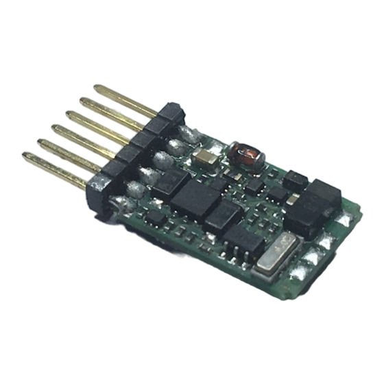
- Page 4 Information Silver mini Pin 1 Kontaktbelegung der NEM651 Schnittstelle Pin allocations of the NEM651 interface Attribution des contacts de l'interface NEM 651 Pin 6 Bedeutung Meaning Signification Motoranschluss 1 Motor connection 1 Sortie moteur 1 Motoranschluss 2 Motor connection 2 Sortie moteur 2 Rechter Radschleifer Right rail pickup...
- Page 5 Nicht geeignet für Kinder unter 3 Jahren wegen verschluckbarer Kleinteile. Bei unsachgemäßem Gebrauch besteht Verletzungsgefahr durch funktionsbedingte Kanten und Spitzen! Nur für trockene Räume. Irrtum sowie Änderung aufgrund des technischen Fortschrittes, der Produktpflege oder anderer Herstellungsmethoden bleiben vorbehalten. Jede Haftung für Schäden und Folgeschäden durch nicht bestimmungsgemäßen Gebrauch, Nichtbeachtung dieser Gebrauchsanweisung, Betrieb mit nicht für Modellbahnen zugelassenen, umgebauten oder schadhaften Transformatoren bzw.
- Page 6 Information Silver mini Not suitable for children under three because of the danger of swallowing the small constituent pieces. Improper use can result in injury from functionally necessary points and edges. For use in dry areas only. We reserve the right to make changes in line with technical progress, product maintenance or changes in production methods.
- Page 7 Wichtige Sicherheitshinweise: Digital plus Lokdecoder dürfen ausschließlich mit dem Digital plus by Lenz System oder anderen, zum NMRA-DCC Standard kompatiblen handelsüblichen Digitalsteuerungen verwendet werden. Fragen Sie im Zweifelsfall beim Lieferanten des Systems nach. Die in den technischen Daten angegebenen Belastbarkeiten dürfen nicht überschritten werden. Sie müssen sicherstellen, dass diese maximale Belastbarkeit nicht überschritten wird.
- Page 8 Information Silver mini Einbau des Silver-mini mit Kabelanschluss (Abb.1, S.3) Notieren Sie sich, welcher Motoranschluss mit den rechten und welcher mit den linken Radschleifern verbunden ist. Dies erspart Ihnen beim Anschluss des Decoders Versuche, welches Kabel des Decoders an welchen Motoranschluss gelötet werden muß, um die richtige Fahrtrichtung einzustellen.
- Page 9 • Funktionsausgang A (weißes Kabel) an das in Fahrtrichtung vordere Birnchen, • Funktionsausgang B (gelbes Kabel) an das in Fahrtrichtung hintere Birnchen. Sind die Glühbirnchen nicht elektrisch mit dem Chassis der Lokomotive verbunden (wir nennen diese dann "potentialfrei"), so schließen Sie den anderen Pol der Lampen an das blaue Kabel an, wie in der Abbildung unten zu sehen ist.
- Page 10 Im Folgenden geben wir Ihnen einen kurzen Überblick über die Eigenschaften des SILVER Decoders und deren Einstellung. Ausführliche Informationen finden Sie im "Handbuch Decoder" welches Sie bei Ihrem Fachhändler erhalten oder sich von der Website der Lenz Elektronik GmbH herunterladen können: www.lenz-elektronik.de 5.1 Leistung und Schutzeinrichtungen Der Motorausgang ist bis 500mA dauernd belastbar, und dies ohne spezielle Montage auf Kühlflächen! Die kurzzeitige Spitzenbelastbarkeit beträgt 800mA.
- Page 11 5.2 Motorsteuerung Der Decoder verfügt über eine hochfrequente Regelung (23kHz). Zur Anpassung an das jeweilige Lokmodell können einfach 6 verschiedene Motortypen in CV50 ausgewählt werden. Diese einzelnen Motortypen enthalten einen Parametersatz der auf die jeweilige Bauart abgestimmt ist. Zusätzlich ist es möglich, bei Auswahl der Motortypen 4 und 5 ein Feintuning über die CV113 und CV114 vorzunehmen.
- Page 12 Information Silver mini 5.4 Abschaltbare Verzögerung Mit der Funktion 4 (Werkseinstellung, kann in CV59 geändert werden) können die Anfahr- und Bremsverzögerung sowie der konstante Bremsweg während des Betriebes abgeschaltet werden. Die Verzögerungen sind abgeschaltet, so lange die Funktion aktiv ist. 5.5 Konstanter Bremsweg Funktionsweise: Beim Übergang von einer beliebigen Fahrstufe zur Fahrstufe 0 (z.B.
- Page 13 Stellen Sie an einem bestimmten Punkt die Fahrstufe auf 0. Drehen Sie dazu an den Handreglern LH30, LH90 und am Compact den Drehknopf an den linken Anschlag, beim LH100 drücken Sie so oft die Fahrstufentaste bis die Fahrstufe 0 bzw. die Lokadresse angezeigt wird (Benutzen Sie am LH100 nicht die Taste , diese erzeugt einen lokspezifischen Nothalt, bei dem die Verzögerungen im Decoder nicht wirksam werden!).
- Page 14 Information Silver mini 5.6 Rangiergang Der Rangiergang halbiert die Geschwindigkeit. Eine besonders feinfühlige Regelung zum Rangieren wird so möglich. Mit der Funktion 3 (Werkseinstellung, kann in CV58 geändert werden) schalten Sie den Rangiergang ein und aus. Wenn der Rangiergang eingeschaltet ist, ist der konstante Bremsweg ausgeschaltet.
- Page 15 5.9 Zuordnung der Funktionsausgänge zu den Funktionen des Digitalsystems (Mapping) Hiermit legen Sie fest, welche Funktion des Digitalsystems die Funktionsausgänge A und B ein- und ausschaltet. Die Ausgänge A und B können der Funktion F0 (richtungsabhängig), oder den Funktionen F1 bis F8 frei zugeordnet werden. Die Zuordnung nehmen Sie in den CVs 33 bis 46 vor.
- Page 16 Information Silver mini Der Decoder ist im Lieferzustand auf Betrieb mit Adresse 3, 28 Fahrstufen, geschwindigkeitsab- hängigem Bremsweg, Funktionsausgänge A und B richtungsabhängig und nicht gedimmt eingestellt. Der Decoder kann sofort mit diesen Einstellungen verwendet werden. Die Einstellungen können selbstverständlich geändert werden. 6.1 Rücksetzen des Decoders auf Werkseinstellung: Wenn Sie alle CVs des Decoders auf Werkseinstellung zurücksetzen möchten, so schreiben Sie in die CV8 den Wert 33.
- Page 17 1-127 Basis – Lokadresse (2-stellig) ® Dies ist die Nummer, mit der Sie die Loks im Digital plus by Lenz ® System aufrufen. Für die Verwendung mit Digital plus by Lenz Geräten ist für die zweistellige Lokadresse nur der Bereich 1-99 zugelassen.
- Page 18 Information Silver mini Bereich 1-99 zugelassen. Einstellungen 1 6 (dec) 1 (0) Richtung der Lok normal: Lok fährt nach vorne, wenn der Pfeil auf dem Handregler nach oben zeigt. vertauscht: Lok fährt nach vorne, wenn der Pfeil auf dem Handregler nach unten zeigt. 2 (1) Fahrstufenmodus: Betrieb mit 14 oder 27 Fahrstufen.
- Page 19 1 (0) Lampen- Kurzschluss 2 (1) Übertemperatur 3 (2) Motor Kurzschluss Werte- Funktionszuordnung (Mapping) für Funktionsausgänge: Werks- bereich Um eine Funktion des Digitalsystems einem Funktionsausgang einstellung zuzuordnen sucht man den Schnittpunkt der Zeile der gewünsch- – ten Funktion mit der Spalte des gewünschten Funktionsaus- gangs.
- Page 20 Information Silver mini 6 (5) EMK-Teiler nicht aktiv EMK-Teiler aktiv 7 (6) Regelung eingeschaltet Regelung ausgeschaltet 8 (7) Motoransteuerung hochfrequent (ca. 23 kHz) Motoransteuerung niederfrequent (ca. 19 Hz) 0 (dec) Brems – Konfiguration 1 (0) konstanter Bremsweg aktiviert 2 (1) ABC aktiviert 3 (2) Richtungsabhängigkeit von ABC ist ausgeschaltet...
- Page 21 zuordnen wollen, so muss das betreffende Bit gesetzt werden. 0-255 Dimmen (kein Mapping werkseitig eingestellt) 0-255 Rangiergang (werkseitige Einstellung F3) 0-255 Abschalten der Verzögerung (werkseitige Einstellung F4) 0-255 Effekte an den F-Ausgängen A und B. Einerstelle des Wertes steht für F-Ausgang A, Zehnerstelle für F-Ausgang B: kein Effekt Marslight Gyralight...
- Page 22 Information Silver mini Important safety instructions Digital plus locomotive decoders are to be used only with Lenz Digital plus or other standard digital control systems with an NMRA-conformance seal. If in doubt, ask the system supplier. Please note that the maximum current-carrying capacity of the outputs may not be exceeded as this...
- Page 23 Installing the SILVER mini via cable connection (Abb. 1, p.3) Please note which motor connection is linked to the right rail pickups and which to the left. If you do this you will not have to try out which decoder cable needs to be soldered to which motor connection to achieve the desired direction of travel.
- Page 24 Information Silver mini • function output A (white cable) to the bulb which is at the front in relation to the direction of travel • function output B (yellow cable) to the bulb which is at the back in relation to the direction of travel If the functions inside the locomotive (e.g.
- Page 25 The following contains a short survey of the features of the SILVER decoder as well as information on how to set them. For more detailed information please refer to the "Decoder operating manual" which is available at your specialist supplier or can be downloaded from the Lenz Elektronik GmbH website: www.lenz-elektronik.de 5.1 Capacity and protection equipment The motor output has a current-carrying capacity of up to 500mA even without special installation on cooling surfaces! The short-term maximum current-carrying capacity is 800mA.
- Page 26 Information Silver mini 5.2 Motor control The decoder has a high-frequency control (23kHz). To adapt it to the type of locomotive used, you can choose between six different motor types in CV50. These motor types include parameter sets which have been specially adapted to the respective models. Moreover, it is possible to carry out fine-tuning via CV113 or CV114 when selecting motor types 4 or 5.
- Page 27 5.5 Constant braking distance Functioning: During the transition from one running notch to running notch 0 (e.g. by moving the turning-knob of the manual control to the left limit-stop), the locomotive/train covers a settable, defined braking distance. This braking distance does not depend on the speed of the locomotive/train.
- Page 28 Information Silver mini Increase or decrease the value in CV52, e.g. in steps of 10, and carry out another measurement. You will thus create a table which will show the braking distances in relation to the values set in CV52. Important advice: The constant braking distance is only effective if the running notch is altered to 0.
- Page 29 also possible. The signal indication "slow approach/caution" does not pose a problem; the respective speed can be set in CV53. You can operate all functions during the signal stop or slow approach – you can even reverse away again from the red signal! These special ABC modules can be used to assemble a very simple block section.
- Page 30 Information Silver mini Programming the decoder The locomotive address, acceleration and deceleration delay, and all other features of the locomotive decoder can be changed as often as desired by reprogramming the decoder. The features are "stored" permanently in special locations even when the operational voltage is switched off.
- Page 31 Ex-works Meaning setting 1-127 Basic locomotive address. This number is used to call up ® locomotives in the Digital plus by Lenz system. The use of range 1-99 is recommended for operation with ® Digital plus by Lenz devices. When writing this CV, CV19 (multiple traction address) is automatically deleted in the decoder and Bit 6 (use of extended address) is deleted in CV29.
- Page 32 Information Silver mini control points up. interchanged: locomotive drives forward if the arrow on the manual control points down. 2 (1) Running-notches mode: Operation with 14 or 27 running notches. This setting is chosen for digital systems which do not support the 28 running-notches mode.
- Page 33 Range of Function mapping for function outputs: Ex-works values In order to allocate a function of the digital system to a function setting output, look for the section where the row of the desired function – meets the column of the desired function output. Enter the number found in the respective CV.
- Page 34 Information Silver mini 8 (7) High-frequency motor control (approx. 23 kHz) Low-frequency motor control (approx. 19 Hz) Braking configuration 0 (dec) 1 (0) Constant braking distance activated 2 (1) ABC activated 3 (2) ABC direction-dependency deactivated 4 (3) Activate push-pull operation without intermediate stop 5 (4) Activate push-pull operation with intermediate stop 6 (5)
- Page 35 0-255 Lighting effect at function outputs A and B. The units digit of the value stands for function output A, the tens digit for function output B: No effect, Marslight, Gyrolight Strobe, Double strobe 0-255 Function mapping: lighting effect at function outputs A and B 0-255 Values for characteristic speed line, default = ex-works speed line 67..
- Page 36 Information Silver mini Remarques importantes Tout décodeur Digital plus est exclusivement destiné à être utilisé avec Lenz DIGITAL plus ou un autre système de pilotage digital du commerce portant le sigle de compatibilité NMRA. En cas de doute, demandez des explications au revendeur du système.
- Page 37 Montage du décodeur SILVER mini avec câbles (fig. 1, page 3) Notez la correspondance entre les bornes du moteur et les patins de prise de courant droits et gauches. Ceci vous évitera de rechercher, lors du raccordement du décodeur, quels câbles du décodeur vous devrez souder aux bornes de sortie du moteur pour que la locomotive roule dans le bon sens.
- Page 38 Information Silver mini Si vous êtes d'accord d'utiliser les sorties de fonction telles que réglées en usine, raccordez alors les sorties comme suit : • sortie A (câble blanc) à l'ampoule avant (selon sens de marche sélectionné) ; • sortie B (câble jaune) à l'ampoule arrière (selon sens de marche sélectionné). Si le second pôle des ampoules n'est pas relié...
- Page 39 Vous trouverez des informations plus détaillées dans le "Manuel du décodeur GOLD" que vous pouvez obtenir auprès de votre détaillant spécialisé ou télécharger sur le site Internet de la firme Lenz Elektronik GmbH : www.lenz-elektronik.de. 5.1 Puissance et sécurité La sortie moteur peut être chargée jusqu'à 500 mA en régime continu et ceci sans le recours spécial à...
- Page 40 Information Silver mini Le décodeur est protégé contre les courts-circuits. En cas d'erreur, un bit correspondant est inscrit dans la CV 30, lequel donne une information au sujet du genre d'erreur. Ce bit peut être effacé par programmation. 5.2 Commande du moteur Le décodeur dispose d'un contrôle du moteur à...
- Page 41 5.3 Crans de vitesse Le décodeur peut être exploité avec les modes de marche à 14/27 ou 28/128 crans de vitesse. Le réglage se fait au moyen de la CV 29. 5.4 Temporisations interruptibles A l'aide de la touche de fonction 4 (réglage d'usine pouvant être modifié dans la CV 60), il est possible de désactiver les temporisations d'accélération et de freinage ainsi que la distance de freinage constante pendant l'exploitation.
- Page 42 Information Silver mini La première chose à faire est de déterminer, sur une petite voie d'essai, la distance de freinage que votre locomotive devra parcourir pour une valeur déterminée dans la CV 52. Commencez par la valeur standard. Activez d'abord la distance de freinage constante (inscrivez le bit 1 dans la CV 51). Si ce bit est effacé, le décodeur exécute la temporisation de freinage dépendant de la vitesse).
- Page 43 La fonction "distance de freinage constante" est également désactivée lorsque les temporisations du décodeur sont désactivées par touche de fonction. Ces deux dernières propriétés peuvent être mises à profit si vous voulez, par exemple, arrêter prématurément une procédure de freinage en cours. En cas de freinage avec du courant continu, la fonction "distance de freinage constante"...
- Page 44 Information Silver mini Pendant l'arrêt au pied du signal ou pendant la marche au ralenti, toutes les fonctions disponibles peuvent être commutées. De plus, effectuer une marche arrière devant la signal rouge est aussi possible ! Un module ABC particulier permet de créer très facilement un block-système. L'ABC est activé...
- Page 45 Programmation du décodeur Au moyen de la PROGRAMMATION, on peut modifier à volonté l'adresse de locomotive, les temporisations d'accélération et de freinage ainsi que toutes les autres propriétés du décodeur. Ces propriétés sont "conservées" de manière permanente au sein du décodeur, même après avoir débranché...
- Page 46 1-127 Adresse de base de locomotive. Ceci est le numéro avec lequel vous appelez la locomotive dans ® le système Digital plus by Lenz . Pour une utilisation avec les ® appareils Digital plus by Lenz , seules les adresses 1-99 sont permises.
- Page 47 6 (déc.) Réglages de niveau 1 1 (0) Sens de marche de la locomotive : Normal : la locomotive roule en avant lorsque la flèche sur l'écran du régulateur pointe vers le haut. Inversé : la locomotive roule en avant lorsque la flèche sur l'écran du régulateur pointe vers le bas.
- Page 48 Information Silver mini 7-8 (6-7) Non utilisé. Annonce d'erreur 0 (déc.) 1 (0) Court-circuit lampes 2 (1) Surchauffe 3 (2) Court-circuit moteur Domaine Attribution des touches de fonction (mapping) aux sorties de Réglage fonction : d'usine valeurs Pour attribuer une touche de fonction du système digital à une –...
- Page 49 (*) Ces valeurs sont sans importance pour les SILVER 10410 et 10411. 0 (déc.) Configuration moteur 1-4 (0-3) Choix du type de moteur 0-5, entrée en nombre décimal. 6 (5) Diviseur FEM non activé Diviseur FEM activé 7 (6) Régulation (compensation de charge) activée Régulation (compensation de charge) désactivée 8 (7) Contrôle du moteur à...
- Page 50 Information Silver mini sec. 0-255 Règle la luminosité aux sorties de fonction A, 255 = max. 0-255 Règle la luminosité aux sorties de fonction B, 255 = max. Attribution des fonctions (mapping): Chaque bit de la CV correspond à une fonction du système digital : bit 1(0) pour fonction 1, bit 2(1) pour fonction 2 et ainsi de suite jusqu'au bit 8(7) pour fonction 8.
- Page 51 0-255 Modulation d'impulsions en largeur minimale avec régulation pour type de moteur 4 ou 5 0-255 Modification du "dutycycle" pour type de moteur 4 ou 5 Numéro de service...
- Page 52 Information Silver mini Hüttenbergstraße 29 D - 35398 Gießen Hotline: 06403 900 133 Fax: 06403 900 155 http://www.digital-plus.de info@digital-plus.de Diese Betriebsanleitung bitte für späteren Gebrauch aufbewahren! Keep this operation manual for future reference! Conservez ce manuel pour une utilisation ultérieure !
Need help?
Do you have a question about the Digital plus Silver mini and is the answer not in the manual?
Questions and answers