Advertisement
Quick Links
The
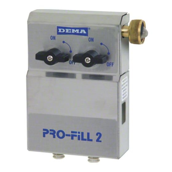
e Model 652G
GAP Dual Sin
1.
PARTS:
ITEM
A
B
C
D
E
F
G
2.
INSTALLAT
TION: (See Fi
This prod
duct is design
and caut
tions identified
A. Moun
nting and Wat
Loca
ate mounting ho
bit fo
or use with the
the in
ncluded anchor
until
they are flush
the s
crew heads ar
throu
ugh the keyhol
sink
does not interf
tubes
s together appro
The w
water inlet is e
The w
water supply c
garde
en hose adapte
OVE
ER TIGHTEN
WAR
RNING: Do n
cause
e the plastic to
B. Chem
mical Supply:
Place
e the chemical
lifts w
will reduce in
foot v
valve and cera
suppl
ly tube to any
the p
proportioner inl
inlet
barb. Repeat t
C. Outlet
t:
For e
each of the prop
outle
t barb. Note: D
I-782
2
Rev.
E-42173
DEMA
A DUAL
MOD
DEL: 652G
INS
STALLATI
nk Dispenser d
dispenses two
DESCRIPT
TION
Dual Sink D
ispenser Assem
¼" I.D. X 8'
Long Vinyl S
Ceramic We
ight
½" ID X 6' L
Long Vinyl Ou
#10 Screw &
& Anchor Kit S
Label Card
Metering Tip
p Kit
igure 1 for setu
up diagram)
ned only to be
e used as des
d in this docu
ment.
WA
ARNING: Insta
allations must
use
e approved ba
ackflow preve
ALW
WAYS DISCO
ONNECT DIS
DIS
SPENSER IS
NOT IN USE
Alw
ways read SDS
S for all chem
er Supply:
oles on a perm
manent surface
included #10 s
screw and anch
rs, drill 1/8" d
diameter holes.
with face of w
wall. Assembl
re sticking out
of the wall ap
e slots in the c
cover and tight
fere with the ou
utlet tubes, put
oximately 4" b
below where th
equipped with
a female garde
can be attached
d to the left sid
r. NOTE: Ap
pply pipe dope
N).
not use Teflon
n® tape to sea
o crack. Use a
a non-welding
containers in
a convenient l
njection capac
cities.) Slip a
amic weight of
f the 8 ft long
convenient len
ngth that will a
let barb. Insta
all open end si
this procedure
for the other c
portioner outle
ets: Cut the 1/2
DO NOT force
e outlet tubing
SINK D
DISPENS
GAP & 65
52GAP-2M
ION INSTR
RUCTIONS
o products int
to a kitchen si
mbly
upply Tubing &
& Foot Valve
utlet Tubing
Set (Total 4 Scr
rews & 4 Anch
scribed in this
s instruction s
t conform to a
all local and n
ntion and pre
essure relief d
SPENSER FR
ROM WATER
.
micals used an
nd follow pers
above sink. D
Drill all of the h
hor set. (If mo
ounting the Dis
) Insert the an
nchors into dri
le all of the #1
0 screws with
pproximately ½
½". Mount th
tening the scre
ews. The unit
tting a strain o
on the proporti
he tubes attach
to the proporti
en hose adapte
er to permit con
de of the unit
by interchang
e, hand tighten
n, and then tu
al internal pl
lastic threads
g liquid sealan
nt instead.
ocation not mo
ore than 6 ft. b
ceramic weigh
ht over a chem
g chemical sup
pply tube into t
allow the tube
e to extend from
ide of the chem
mical supply tu
hemical contai
iner.
2" I.D. outlet tu
ubing to the de
g onto the larg
ger barbs on t
10/04/16
SER
M
ink with the tu
urn of a ball v
QT
Assembly
hors)
heet. Adhere
e to all warnin
national plumb
bing codes an
devices where
e required.
R SOURCE W
WHEN
sonal protecti
ve guidelines
holes into the d
drywall using
spenser to woo
od and you do n
illed holes and
d hammer them
h a Phillips scre
ewdriver into t
he Dispenser b
by inserting the
needs to be m
mounted high en
oners. If this
is not possible
ioners.
nnection to the
e right hand si
ing the plug in
n the left-hand
urn 1-1/2 time
es with a wren
as the extra
thickness of t
below the disp
ensing unit. (N
mical supply tu
ube. Insert the
the chemical c
container. Cut
m the bottom
of the chemica
ube by pushing
g the tube ove
esired length an
nd attach to th
the proportion
ner.
valve.
TY.
1
1
2
2
2
2
1
1
1
1
1
1
1
1
ngs
nd
s.
a ¼" diameter
not plan to use
m into the wall
the anchors so
e screw heads
nough that the
e, tie the outlet
ide of the unit.
d side with the
nch (DO NOT
the tape may
Note: greater
e end with the
t the chemical
al container to
er proportioner
he proportioner
Pg
g. 1 of 5
Advertisement

Related Manuals for DEMA 652GAP


Summary of Contents for DEMA 652GAP
- Page 1 DEMA A DUAL SINK D DISPENS DEL: 652G GAP & 65 52GAP-2M STALLATI ION INSTR RUCTIONS e Model 652G GAP Dual Sin nk Dispenser d dispenses two o products int to a kitchen si ink with the tu urn of a ball v valve.
-
Page 2: Operation
3. OPERATION: The model 652GAP is activated by turning one of the two on-off ball valves fully counter-clockwise. (In order for the unit to operate properly, only one ball valve should be open.) When the desired amount of chemical water solution has been obtained turn the ball valve fully clockwise. -
Page 3: Warranty
This warranty is extended only to the original buyer of DEMA products. If products are altered or repaired without prior approval of DEMA, this warranty will be void. - Page 4 DEMA DUAL SINK DISPENSER MODEL: 652GAP & 652GAP-2M INSTALLATION INSTRUCTIONS PART NO. DESCRIPTION 150-6 Rubber Washer 100-38 Strainer Washer 61-22-3 4 GPM Proportioner – ¼” Inlet Barb 65-10 Hose Coupling 61-21 ½” ID X 6’ Lg. Vinyl Tubing 65-17-2 Hose Adapter Stem...
- Page 5 DEMA DUAL SINK DISPENSER MODEL: 652GAP & 652GAP-2M INSTALLATION INSTRUCTIONS MODEL: 652GAP-2M PART NO. DESCRIPTION 61-22-3 4 GPM Proportioner – ¼’ Inlet Barb 25-51-12 ¼” NPT X 3/8” O.D. Tube 61-21 ½” ID X 6’ Lg. Vinyl Tubing Compression Fitting...
Need help?
Do you have a question about the 652GAP and is the answer not in the manual?
Questions and answers