Table of Contents
Advertisement
Quick Links
I.
PARTS:
A.
Dispenser assembly
B.
1 pc. 9/16 in. I.D. X 6 ft. vinyl outlet tubing.
C.
2 pc. 3/8 in. O.D. X 8 ft. vinyl supply tubing, foot valve & ceramic weight.
D.
4 pc. #10 pan head 3/4 in. long mounting screw.
E.
4 pc. 7/8 in. long plastic mounting anchor.
F.
1 pc. Metering tip kit.
II.
INSTALLATION: (See Figure 1 for setup diagram)
This product is designed only to be used as described in this instruction sheet. Adhere to all warnings and
cautions identified in this document.
A.
Mounting and Water Supply:
Locate mounting holes on a permanent surface above sink. Drill holes about 1" deep and insert mounting
anchors. Mount the unit using screws inserted through the keyholes in the case. Secure unit by inserting screws
into the lower 2 holes. The unit needs to be mounted high enough that the sink does not interfere with the outlet
tubes, putting a strain on the proportioners. If this is not possible, tie the outlet tubes together approximately 4"
below where the tubes attach to the proportioners.
The water inlet is equipped with a female garden hose adapter to permit connection to the right hand side of the
unit. The water supply can be attached to the left side of the unit by interchanging the plug in the left-hand side
with the garden hose adapter. Note: The water supply pressure should not exceed 150 psi.
B.
Chemical Supply:
Place the chemical containers in a convenient location not more than 6 ft. below the dispensing unit. Note:
greater lifts will reduce injection capacities. Insert the ends with the foot valves of the 8 ft long, 3/8 in. O.D.
vinyl tubes into the chemical containers. Cut the vinyl tubes to any convenient length that will allow the tubes
to extend from the bottom of the chemical container to the proportioner inlet barb. Slide the ceramic weights
over the 3/8 in. O.D. tubing and down to the foot valves. Repeat this procedure for both containers.
I-557
Rev. C-41469 3/7/16
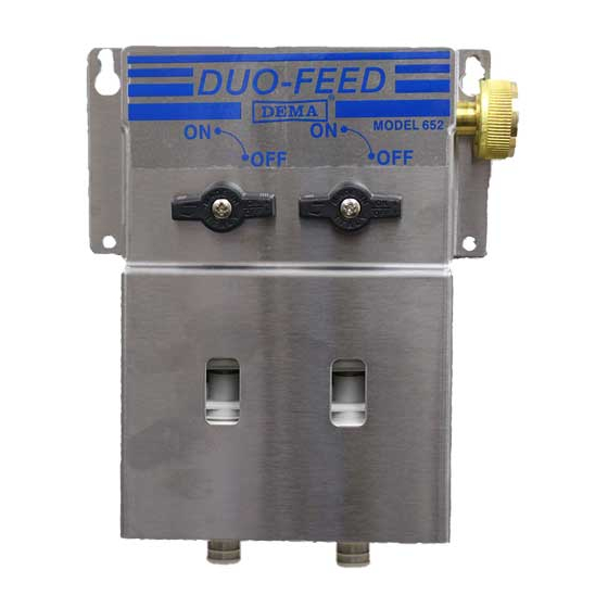
DEMA 652AG DUO-FEED
WARNING: Installations must conform to all local and national plumbing codes and use
approved backflow prevention and pressure relief devices where required.
ALWAYS DISCONNECT DISPENSER FROM WATER SOURCE WHEN DISPENSER
IS NOT IN USE.
Always read SDS for all chemicals used and follow personal protective guidelines.
Pg. 1 of 5
Advertisement
Table of Contents

Related Manuals for DEMA 652AG


Summary of Contents for DEMA 652AG
-
Page 1: Installation Instructions
DEMA 652AG DUO-FEED INSTALLATION INSTRUCTIONS PARTS: Dispenser assembly 1 pc. 9/16 in. I.D. X 6 ft. vinyl outlet tubing. 2 pc. 3/8 in. O.D. X 8 ft. vinyl supply tubing, foot valve & ceramic weight. 4 pc. #10 pan head 3/4 in. long mounting screw. - Page 2 OPERATION: The model 652AG is activated by turning one of the two on-off ball valves fully counter-clockwise. When the desired amount of chemical water solution has been obtained turn the ball valve fully clockwise. Note: Do not use ball valves to throttle chemical water flow rate;...
- Page 3 DEMA 652AG DUO-FEED INSTALLATION INSTRUCTIONS 1 cps (centipoise) is equal to the viscosity of water 75 cps is approximately equal to the viscosity of 10 weight motor oil 200 cps is approximately equal to the viscosity of most dishwashing detergents TABLE 1 (163BAG - 4 GPM FLOW RATE PROPORTIONER, 1/4"...
- Page 4 “o”- rings, diaphragms, squeeze tubing and gaskets are considered expendable and are not covered under warranty. This warranty is extended only to the original buyer of DEMA products. If products are altered or repaired without prior approval of DEMA, this warranty will be void.
- Page 5 I-557 Pg. 5 of 5 Rev. C-41469 3/7/16...
Need help?
Do you have a question about the 652AG and is the answer not in the manual?
Questions and answers